EP1081029B1 - Procédé de montage en aveugle d'au moins un composant et dispositif de mise en oeuvre de ce procédé - Google Patents
Procédé de montage en aveugle d'au moins un composant et dispositif de mise en oeuvre de ce procédé Download PDFInfo
- Publication number
- EP1081029B1 EP1081029B1 EP00402356A EP00402356A EP1081029B1 EP 1081029 B1 EP1081029 B1 EP 1081029B1 EP 00402356 A EP00402356 A EP 00402356A EP 00402356 A EP00402356 A EP 00402356A EP 1081029 B1 EP1081029 B1 EP 1081029B1
- Authority
- EP
- European Patent Office
- Prior art keywords
- door
- component
- wall
- cassette
- components
- Prior art date
- Legal status (The legal status is an assumption and is not a legal conclusion. Google has not performed a legal analysis and makes no representation as to the accuracy of the status listed.)
- Expired - Lifetime
Links
Images




Classifications
-
- B—PERFORMING OPERATIONS; TRANSPORTING
- B62—LAND VEHICLES FOR TRAVELLING OTHERWISE THAN ON RAILS
- B62D—MOTOR VEHICLES; TRAILERS
- B62D65/00—Designing, manufacturing, e.g. assembling, facilitating disassembly, or structurally modifying motor vehicles or trailers, not otherwise provided for
-
- Y—GENERAL TAGGING OF NEW TECHNOLOGICAL DEVELOPMENTS; GENERAL TAGGING OF CROSS-SECTIONAL TECHNOLOGIES SPANNING OVER SEVERAL SECTIONS OF THE IPC; TECHNICAL SUBJECTS COVERED BY FORMER USPC CROSS-REFERENCE ART COLLECTIONS [XRACs] AND DIGESTS
- Y10—TECHNICAL SUBJECTS COVERED BY FORMER USPC
- Y10T—TECHNICAL SUBJECTS COVERED BY FORMER US CLASSIFICATION
- Y10T29/00—Metal working
- Y10T29/49—Method of mechanical manufacture
- Y10T29/49826—Assembling or joining
- Y10T29/49895—Associating parts by use of aligning means [e.g., use of a drift pin or a "fixture"]
-
- Y—GENERAL TAGGING OF NEW TECHNOLOGICAL DEVELOPMENTS; GENERAL TAGGING OF CROSS-SECTIONAL TECHNOLOGIES SPANNING OVER SEVERAL SECTIONS OF THE IPC; TECHNICAL SUBJECTS COVERED BY FORMER USPC CROSS-REFERENCE ART COLLECTIONS [XRACs] AND DIGESTS
- Y10—TECHNICAL SUBJECTS COVERED BY FORMER USPC
- Y10T—TECHNICAL SUBJECTS COVERED BY FORMER US CLASSIFICATION
- Y10T29/00—Metal working
- Y10T29/49—Method of mechanical manufacture
- Y10T29/49826—Assembling or joining
- Y10T29/49904—Assembling a subassembly, then assembling with a second subassembly
-
- Y—GENERAL TAGGING OF NEW TECHNOLOGICAL DEVELOPMENTS; GENERAL TAGGING OF CROSS-SECTIONAL TECHNOLOGIES SPANNING OVER SEVERAL SECTIONS OF THE IPC; TECHNICAL SUBJECTS COVERED BY FORMER USPC CROSS-REFERENCE ART COLLECTIONS [XRACs] AND DIGESTS
- Y10—TECHNICAL SUBJECTS COVERED BY FORMER USPC
- Y10T—TECHNICAL SUBJECTS COVERED BY FORMER US CLASSIFICATION
- Y10T29/00—Metal working
- Y10T29/53—Means to assemble or disassemble
- Y10T29/53978—Means to assemble or disassemble including means to relatively position plural work parts
Definitions
- the present invention relates to a blind mounting method at least one component and one device for implementing this method.
- the blind assembly of components is a problem for especially automobile manufacturers.
- This method and this device are especially used when assembling a multi-function plate in a opening element for vehicle.
- the opening element may be a door or a vehicle tailgate.
- US 2,935,314 describes a tool for positioning a part fixing for corrugated sheet on the underside which is difficult to access.
- the first object of the present invention is therefore to overcome the disadvantages of the prior art by proposing a method allowing the blind positioning and mounting of components.
- the second wall forms with the first a volume.
- the three-dimensional connection is rigid in X and Z and stiffenable in Y by a key.
- the step of mounting and joining together the unit formed by the cassette and all the interior elements inside of a vehicle door consists, on the one hand in securing each element on the walls of the door, and on the other hand to be joined, when this is required, at least one mechanism of each element to a mechanism of the cassette.
- a second object of the invention is to propose a device allowing the implementation of the method according to the invention.
- a removable connection means comprises a bar comprising means allowing its locking on the one hand on the cassette and on the other hand on one of the components, these locking means being unlockable once all the components are in place in the door in order to free the glass circulation well.
- a retractable connecting means includes a threaded sleeve ensuring, by means of securing, the connection between the cassette and an internal component, the thread of the sleeve being intended to collaborate with a screw for fixing to a wall of the door of one of the interior elements, the retraction of the sleeve being obtained by screwing in the fixing screw when the inner element is attached to the door.
- FIG. 1 represents a simplified diagram of the principle of the invention which consists of forming rigid links L1, L2, L3 on a multifunction plate (10) allowing to position in space each of the components C1, C2, C3 which must be mounted blind in housings provided for C1 in a second wall (52), for C2 in the same wall (51) and for C3 in a third wall (53).
- the multi-function plate is positioned in a housing or a recess (510) allowing its positioning on the wall (51).
- This wall (51) is also provided with orifices (511 and 512) of sizes sufficient to allow the passage of the component and the positioning link in space this component.
- each of the components C1, C2, C3 is positioned opposite from their respective accommodation.
- Component C3 can be, as shown in FIG. 9, a keyboard of switches controlling the electric windows placed on the flat part of an armrest formed in a recess (530).
- Component C1 can be the external control opening doors to operate the vehicle lock.
- FIG. 2 represents an application of this type of the method of the invention in which we find the cutout (521) allowing the fixing of the external part CE on the component C1 which is constituted by the control opening (4) which is mechanically connected to the lock (3) of the door and the assembly being connected by a link (21-22) to the multifunction plate (10).
- the door has a first interior wall (51) provided with two cutouts (511-512) through which you can see the inside of the outer wall at 52 defining the volume of the door in which the glass can be retracted.
- Line (510) defines the outline of the recess forming the means for positioning the multifunction plate (10).
- Well glass is accessible by the lower edge (55) forming the frame of the door.
- a cutout (56) allows to receive the housing (3) lock.
- FIGS. 8A, 8B The part external CE which is fixed on the component (4) is shown in FIGS. 8A, 8B and consists of a covering (53 or 53B) which, using screws, comes sandwich the wall (52) with component C1 and this covering (53) is provided with openings (535) allowing the clipping of an operating member (533) in the additional elements provided for this purpose in the order door opening opening constituting component C1.
- the legs (21, 22) are shaped so as not to enter the well (54) door.
- the positioning then the complete locking in translation and rotation of the components (3, 4) relative to to the cassette (1) must be secured to avoid any risk of discrepancy, when the final assembly of the components (3, 4) in the door.
- the blocking is ensured by at least one removable connection means (20) or retractable, described in detail later.
- the removable connection means (20) consists of a bar (20) integral with, on the one hand, the external control (4) for opening, and on the other hand from the wall (10) of the cassette (1).
- connection between the bar (20) and the wall (10) of the cassette (1) is provided, for example, by a tongue (12) provided with a hole.
- the tongue is formed in a cutout (11) of the wall (10).
- the hole of determined size and geometry, can be practiced directly in the wall (10).
- the bar (20) is then engaged in the bore (12) of the wall (10), and in a second bore (41) made on part of the external opening control (4). So once the components (3, 4) secured to the wall (10) of the cassette (1) by through the tabs (21, 22), this bar (20) blocks the components (3, 4) in an optimal position for fixing in the door.
- this bar (20) on the cassette and on the technical part of the external opening control (4) is such that an operator can remove the bar (20), once all the components (3, 4) are mounted in the door, by through a gripping means (201) located on a first end of the bar (20) and projecting from the outer face of the wall (10) of the cassette (1).
- the outer part (53) comprises means (533) to allow attachment to the outer wall (52) of the door (5) and means for mounting the pallet (533b).
- the outer wall (52) can include a deep drawing allowing the positioning and / or centering of the external part (53), during its assembly.
- the outer wall (52) includes also holes for the passage of COE fasteners on the outer part, so that once the assembly has been carried out, the wall (52) is taken between the outer part (53) and the COE (4), which allows the solidarity of the WCC.
- Fasteners include, for example, pins which also allow the positioning of the COE (4).
- the mechanical connection between the external part (53) and the COE (4) is then carried out by screws screwed into the pins.
- FIG. 4 represents an exemplary embodiment of a connection means removable.
- a removable connection means is, for example, consisting of a bar (20).
- This bar (20) is, for example, consisting of a cylindrical bar on which two flats are made parallel.
- the dimensions and geometry of the cross section of the bar (20) are substantially identical to the dimensions and geometry of the bore of the tab or hole (12) in the wall (10, fig. 2) of the cassette (1), and piercing (41, fig. 2) of the COE or piercing the tongue (42, fig. 3) of the WCC.
- Each end (201, 202) of the bar (20) comprises means (201, 202) for gripping or handling consisting, for example, of a handle (201, 202).
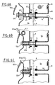
- FIGS. 5A to 5C represent the different stages of implementation place and removal of the removable connecting means of the example of embodiment of FIG. 4.
- the bar (20) is, initially, shown in Figure 5A, inserted between the wall (10) of the cassette, and for example a tongue (42) of the COE, by drilling the wall (10) of the cassette, and by drilling (420) the tongue (42).
- the introduction of the bar (20) can be carried out either by first inserting the bar (20) by drilling (120) of the wall (10), either by first introducing the bar (20) through the drilling (420) of the tongue (42).
- the introduction of the bar (20), shown FIG. 5B, is carried out until the first (203), respectively the second grooves (204) are opposite the bore (120) of the wall (10), respectively of the bore (420) of the tongue (42).
- the bar (20) is locked between the wall (10) and the COE and therefore ensures the mounting and blocking in translation and rotation of the COE with respect to the cassette, which facilitates mounting of the COE and possibly other door components.
- FIGS. 6A to 6C represent the different stages of implementation place and retraction of a first alternative embodiment of a means of retractable link.
- the connecting means ensuring the locking in rotation and in translation is not removable but is retractable, i.e. it is not removed once the door components mounted in the door, but simply operated to release the well (54) door.
- the wall (10) of the cassette comprises an opening (13) extended towards the well (54) of the door by a tube (14).
- the end of this tube (14) located inside the well (54), includes a seal (71) in which is fitted a first end of a nut (7), or threaded sleeve, of which the second end is engaged in a first end of a sleeve (43) practiced in the tongue (42) or extension of the COE.
- Geometry and the dimensions of the sleeve (43) are substantially identical to the geometry and to the dimensions of the nut (7) so that the only movement of the nut (7) in the sleeve (43) or the sliding.
- FIG. 6A represents the positioning step of a door component, for example, the WCC.
- the COE is mounted on the wall (10) of the cassette by the intermediary, in particular of the nut (7). Then the cassette is mounted in the door.
- the next step, for the variant embodiment shown on the Figures 6A to 6C, consists of fixing the COE to the door and mounting the part exterior (534) on the exterior wall (52) of the door.
- the outer part (53) is then pressed against the outer wall (52) of the door and the end of the bar (80) is engaged in the sleeve (541) of the outer part (53).
- the final determination of the external part (53), as well as the release of the well (54), represented figure 7C, are obtained by screwing the screw (8) into the sleeve (541) of the part exterior (53) equipped for this purpose, for example, with a threaded insert.
- the method and the device according to the invention allow to facilitate the operation of mounting components inside a door. Indeed, all components can be positioned for mounting blind in the door in a single operation which consists in inserting, into the door, the cassette previously fitted with the various components. Finally, the different embodiments of the removable connection means or retractable depend, on the one hand, on the configuration of the components and of the door, and on the other hand the choice of the user as to reuse or not connecting means allowing the blocking of all the components.
Landscapes
- Engineering & Computer Science (AREA)
- Manufacturing & Machinery (AREA)
- Chemical & Material Sciences (AREA)
- Combustion & Propulsion (AREA)
- Transportation (AREA)
- Mechanical Engineering (AREA)
- Lock And Its Accessories (AREA)
- Automobile Manufacture Line, Endless Track Vehicle, Trailer (AREA)
- Automatic Assembly (AREA)
- Vehicle Step Arrangements And Article Storage (AREA)
- Connection Of Plates (AREA)
Description
- une étape de liaison tridimensionnelle du composant par un lien avec une platine multifonction;
- une étape de formation de moyens de positionnement de la platine multifonctionnelle dans une première paroi pourvue d'au moins un trou permettant le passage du lien et du composant, le dit lien positionnant dans l'espace le composant pour qu'après positionnement de la platine, le composant soit en place dans le logement;
- une étape de fixation de composants supplémentaires sur le composant.
- une étape de rigidification d'un composant sur une cassette multifonction
- une étape de fixation de la cassette dans un logement prévu sur la deuxième paroi et de positionnement d'un composant sur la face interne de la paroi extérieure de l'élément ouvrant
- une étape de suppression de la rigidification
- une étape de montage des composants extérieurs de manoeuvre et d'habillage.
- la figure 1 représente un schéma simplifié du dispositif permettant la mise en oeuvre du procédé.
- la figure 2 représente un schéma du dispositif permettant la mise en oeuvre du procédé selon l'invention,
- la figure 3 représente une vue en coupe transversale d'une première variante de réalisation du dispositif selon l'invention,
- la figure 4 représente un exemple de réalisation d'un moyen de liaison amovible,
- les figures 5A à 5C représentent les différentes étapes de mise en place et d'enlèvement de l'exemple de réalisation du moyen de liaison amovible de la figure 4,
- les figures 6A à 6C représentent les différentes étapes de mise en place et d'escamotage d'une première variante de réalisation d'un moyen de liaison escamotable,
- les figures 7A à 7C représentent les différentes étapes de mise en place et d'escamotage d'une deuxième variante de réalisation d'un moyen de liaison escamotable,
- les figures 8A et 8B représentent une première, respectivement une deuxième variante, de réalisation d'un boítier extérieur d'une commande d'ouverture de porte.
- la figure 9 représente une vue en perspective d'une utilisation du procédé défini par rapport à la figure 1.
Claims (18)
- Procédé de montage en aveugle d'au moins un composant destiné à être mis en place dans un logement difficilement accessible comprend :une étape de liaison tridimensionnelle du composant par un lien avec une platine multifonction;une étape de formation de moyens de positionnement de la platine multifonctionnelle dans une première paroi pourvue d'au moins un trou permettant le passage du lien et du composant, le dit lien positionnant dans l'espace le composant pour qu'après positionnement de la platine, le composant soit en place dans le logement;une étape de fixation de composants supplémentaires sur le composant
- Procédé de montage selon la revendication 1, caractérisé en ce qu'il comprend un logement solidaire d'une deuxième paroi.
- Procédé de montage selon la revendication 2, caractérisé en ce qu'il comprend une seconde paroi formant avec la première un volume.
- Procédé de montage selon une des revendications 1 à 3, caractérisé en ce qu'il comprend des composants complémentaires qui sont un composant d'habillage et un composant de manoeuvre.
- Procédé de montage selon la revendication 3, caractérisé en ce qu'il comprend un volume qui est un ouvrant de véhicule.
- Procédé de montage selon une des revendications 1 à 5, caractérisé en ce qu'il comprend une liaison tridimensionnelle rigide en X et Z et rigidifiable en Y par une clé.
- Procédé de montage selon une des revendications 1 à 6, caractérisé en ce qu'il comprend une platine multifonctionnelle qui est une cassette de porte de véhicule.
- Procédé de montage, selon la revendication 5, en aveugle d'un composant dans un volume constituant un élément ouvrant formé d'une première paroi (52) extérieure et d'une deuxième paroi (1) intérieure caractérisé en ce qu'il comprendune étape de rigidification d'un composant sur - une cassette multifonction (10),une étape de fixation de la cassette dans un logement prévu sur la deuxième paroi et de positionnement d'un composant (3, 4) sur la face interne, de la paroi (52) extérieure de l'élément ouvrant,une étape de suppression de la rigidificationune étape de montage des composants extérieurs de manoeuvre et d'habillage.
- Procédé de montage selon la revendication 8, caractérisé en ce que l'élément ouvrant est une portière ou un hayon, l'espace de suppression de la rigidification libère l'espace entre les deux parois formant un puits (54), pour un élément mobile tel qu' une vitre (6), pour un des composants (3, 4) destiné à être monté, est la partie technique d'une commande extérieure (4) d'ouverture.
- Procédé de montage selon la revendication 8 ou 9, caractérisé en ce qu'il comprend une étape de montage de la partie extérieure (53) de la commande d'ouverture de porte comprenant un organe de manoeuvre et/ou un habillage à l'extérieur de la portière, le montage étant réalisé par fixation sur la commande d'ouverture extérieure (4) pour enserrer la paroi (52) entre la partie extérieure (53) et la partie technique de la commande (4) extérieure d'ouverture.
- Procédé de montage selon l'une des revendications 8, caractérisé en ce que l'étape de rigidification est assurée par un moyen de liaison amovible comprend un barreau (20) comportant des moyens (203, 204) permettant son verrouillage, d'une part sur la seconde paroi (1), et d'autre part sur un des composants (4) destiné à être monté à l'intérieur du volume (5), ces moyens (203, 204) de verrouillage étant déverrouillables une fois le composant (4) mis en place et fixé dans le volume (5), afin de libérer l'espace (53) entre les deux parois du volume.
- Procédé de montage selon l'une des revendications 8 à 11, caractérisé en ce que l'étape de montage et de solidarisation de l'ensemble formé par la cassette (1) et tous les éléments (3, 4) intérieurs à l'intérieur d'une portière (5) de véhicule consiste, d'une part à solidariser chaque élément (3,4) aux parois (52) de la portière, et d'autre part à solidariser, lorsque cela est nécessaire, au moins un mécanisme de chaque élément (4) à un mécanisme de la cassette (1).
- Dispositif de montage d'au moins un composant caractérisé en ce qu'il comprend des moyens (7, 8, 20, 21, 22) de liaison amovible du ou des composants (3, 4) à une cassette (1) destinée à être montée à l'intérieur d'un élément ouvrant de véhicule, les moyens (7, 8, 20, 21, 22, 23) de liaison amovible étant conformés pour assurer le blocage en rotation et en translation par rapport à la cassette (1) du ou des composants (3, 4) à monter à l'intérieur de l'élément ouvrant.
- Dispositif de montage selon la revendication 13, caractérisé en ce qu'un moyen de liaison amovible comprend un barreau (20) comportant des moyens (203, 204) permettant son verrouillage, d'une part sur la cassette (1), et d'autre part sur un des composants(4), ces moyens (203, 204) de verrouillage étant déverrouillables une fois tous les composants(4) mis en place dans la portière afin de libérer le puits (54).
- Dispositif de montage selon la revendication 13, caractérisé en ce qu'un moyen de liaison escamotable comprend un manchon (7) taraudé assurant par des moyens (14, 42) de solidarisation, la liaison entre la cassette (1) et un composant (4) intérieur, le taraudage du manchon (7) étant destiné à collaborer avec une vis (531) de fixation d'un des éléments (4) intérieurs, l'escamotage du manchon (7) étant obtenu par vissage de la vis (531) de fixation lors de la solidarisation de l'élément intérieur (4) sur la portière (5).
- Dispositif de montage selon l'une des revendications 13 à 15, caractérisé en ce que les composants (3, 4) intérieurs de portière comprennent, d'une part la partie technique d'une commande extérieure d'ouverture (4) destinée à être solidarisée à la surface intérieure de la tôle formant la paroi extérieure de la portière, par l'intermédiaire d'une partie extérieure (53) positionnée sur un embouti de la surface extérieure de la tôle et des moyens de fixation assurant la liaison mécanique entre la partie extérieure et la partie technique commande (4) extérieure d'ouverture, et/ou d'autre part le mécanisme (3) de serrure de la portière.
- Dispositif de montage selon l'une des revendications 13 à 16, caractérisé en ce qu'il comprend une partie extérieure constituée d'un habillage et d'un organe de préhension.
- Dispositif de montage d'au moins un élément intérieur de portière de véhicule selon la revendication 10, caractérisé en ce que la paroi extérieure (52) de la portière comprend un renfoncement ou une découpe de centrage de la partie extérieure (53), cette dernière comportant des puits (530) de centrage qui pénètrent dans des broches de la commande d'ouverture extérieure, les puits recevant une vis de liaison de la partie extérieure (53) avec la partie technique de la commande extérieure (4) d'ouverture .
Applications Claiming Priority (2)
| Application Number | Priority Date | Filing Date | Title |
|---|---|---|---|
| FR9911121A FR2798111B1 (fr) | 1999-09-06 | 1999-09-06 | Procede de montage en aveugle d'au moins un composant et dispositif de mise en oeuvre de ce procede |
| FR9911121 | 1999-09-06 |
Publications (2)
| Publication Number | Publication Date |
|---|---|
| EP1081029A1 EP1081029A1 (fr) | 2001-03-07 |
| EP1081029B1 true EP1081029B1 (fr) | 2003-05-21 |
Family
ID=9549567
Family Applications (1)
| Application Number | Title | Priority Date | Filing Date |
|---|---|---|---|
| EP00402356A Expired - Lifetime EP1081029B1 (fr) | 1999-09-06 | 2000-08-24 | Procédé de montage en aveugle d'au moins un composant et dispositif de mise en oeuvre de ce procédé |
Country Status (7)
| Country | Link |
|---|---|
| US (1) | US6532640B1 (fr) |
| EP (1) | EP1081029B1 (fr) |
| JP (1) | JP2001138741A (fr) |
| CA (1) | CA2317923A1 (fr) |
| DE (1) | DE60002800T2 (fr) |
| ES (1) | ES2199749T3 (fr) |
| FR (1) | FR2798111B1 (fr) |
Families Citing this family (1)
| Publication number | Priority date | Publication date | Assignee | Title |
|---|---|---|---|---|
| DE102016116133B3 (de) | 2016-08-30 | 2018-01-25 | i.GLUESYSTEMS GmbH | Mehrkammerbeutel |
Family Cites Families (4)
| Publication number | Priority date | Publication date | Assignee | Title |
|---|---|---|---|---|
| US2935314A (en) * | 1957-04-01 | 1960-05-03 | Johns Manville | Fastener holding tool |
| JP3080732B2 (ja) * | 1991-11-15 | 2000-08-28 | マツダ株式会社 | 自動車のトランクリッド組付装置 |
| DE19741062A1 (de) * | 1997-09-18 | 1999-04-01 | Rehau Ag & Co | Mehrfunktionsschiene |
| US6006635A (en) * | 1998-05-22 | 1999-12-28 | Chrysler Corporation | Setting fixture |
-
1999
- 1999-09-06 FR FR9911121A patent/FR2798111B1/fr not_active Expired - Fee Related
-
2000
- 2000-08-24 DE DE60002800T patent/DE60002800T2/de not_active Expired - Fee Related
- 2000-08-24 ES ES00402356T patent/ES2199749T3/es not_active Expired - Lifetime
- 2000-08-24 EP EP00402356A patent/EP1081029B1/fr not_active Expired - Lifetime
- 2000-08-30 CA CA002317923A patent/CA2317923A1/fr not_active Abandoned
- 2000-09-01 JP JP2000264927A patent/JP2001138741A/ja not_active Withdrawn
- 2000-09-06 US US09/656,217 patent/US6532640B1/en not_active Expired - Fee Related
Also Published As
| Publication number | Publication date |
|---|---|
| US6532640B1 (en) | 2003-03-18 |
| EP1081029A1 (fr) | 2001-03-07 |
| ES2199749T3 (es) | 2004-03-01 |
| CA2317923A1 (fr) | 2001-03-06 |
| FR2798111B1 (fr) | 2001-10-12 |
| FR2798111A1 (fr) | 2001-03-09 |
| DE60002800T2 (de) | 2004-03-18 |
| JP2001138741A (ja) | 2001-05-22 |
| DE60002800D1 (de) | 2003-06-26 |
Similar Documents
| Publication | Publication Date | Title |
|---|---|---|
| EP1026351B1 (fr) | Poignée d'ouvrant de véhicule automobile comportant des moyens perfectionnés de blocage d'un élément externe | |
| EP1159149A1 (fr) | Toit repliable pour vehicule decouvrable | |
| EP0088699A1 (fr) | Porte-clefs du type à clef escamotable dans un boitier | |
| FR2789426A1 (fr) | Poignee d'ouvrant de vehicule automobile | |
| FR2589403A1 (fr) | Mecanisme de reglage de phare d'automobile et son boitier | |
| EP0980948B1 (fr) | Dispositif de montage de commande d'ouverture de porte de véhicule | |
| FR2773580A1 (fr) | Procede de montage d'un boitier de serrure de portiere de vehicule automobile, serrure destinee a etre montee par ce procede et fourche utilisee pour ce montage | |
| EP1081029B1 (fr) | Procédé de montage en aveugle d'au moins un composant et dispositif de mise en oeuvre de ce procédé | |
| EP0721044A1 (fr) | Support destiné à être monté sur un chariot de lève-vitre de véhicule automobile | |
| FR2789429A1 (fr) | Poignee d'ouvrant de vehicule automobile comportant des moyens perfectionnes de montage d'un levier de prehension | |
| EP1020337A1 (fr) | Antivol de direction de véhicule automobile | |
| EP1948499B1 (fr) | Dispositif d'ecartement securise a l'arrachement | |
| EP2048379B1 (fr) | Garniture pour glace, ouvrant équipé d'une telle garniture et procédé de positionnement associé | |
| EP1059409B1 (fr) | Dispositif de renvoi de fouillot | |
| EP0742329B1 (fr) | Dispositif de verrouillage d'un ouvrant de véhicule automobile comportant des moyens perfectionnés de montage d'un capuchon d'habillage | |
| EP0673806B1 (fr) | Dispositif de montage d'un pare-chocs sur la carrosserie d'un vehicule automobile. | |
| EP3967838B1 (fr) | Dispositif de commande d'ouverture pour une porte d'un véhicule automobile | |
| EP1388447A1 (fr) | Porte pour espace de chargement et véhicule industriel pourvu d'au moins une telle porte | |
| EP0621388A1 (fr) | Porte à serrure-bandeau, comportant des moyens perfectionnés de montage de la serrure sur la porte | |
| FR2776574A1 (fr) | Leve-vitre pour une vitre montee mobile dans une structure sans cadre d'une porte d'un vehicule automobile | |
| FR2538840A1 (fr) | Butee reglable pour un battant de menuiserie et notamment pour des fenetres, des volets, ou des portes-fenetres | |
| FR2896816A1 (fr) | Dispositif pour verrouiller une porte d'un vehicule | |
| EP0828050A1 (fr) | Charnière de porte, notamment pour véhicule automobile | |
| EP1008710A1 (fr) | Ferrure de verrouillage du type crémone | |
| EP3549803A1 (fr) | Assemblage par glissement d'une vitre et d'un hayon de véhicule automobile |
Legal Events
| Date | Code | Title | Description |
|---|---|---|---|
| PUAI | Public reference made under article 153(3) epc to a published international application that has entered the european phase |
Free format text: ORIGINAL CODE: 0009012 |
|
| AK | Designated contracting states |
Kind code of ref document: A1 Designated state(s): DE ES FR IT SE |
|
| AX | Request for extension of the european patent |
Free format text: AL;LT;LV;MK;RO;SI |
|
| 17P | Request for examination filed |
Effective date: 20010607 |
|
| AKX | Designation fees paid |
Free format text: DE ES FR IT SE |
|
| GRAH | Despatch of communication of intention to grant a patent |
Free format text: ORIGINAL CODE: EPIDOS IGRA |
|
| GRAH | Despatch of communication of intention to grant a patent |
Free format text: ORIGINAL CODE: EPIDOS IGRA |
|
| GRAA | (expected) grant |
Free format text: ORIGINAL CODE: 0009210 |
|
| AK | Designated contracting states |
Designated state(s): DE ES FR IT SE |
|
| REF | Corresponds to: |
Ref document number: 60002800 Country of ref document: DE Date of ref document: 20030626 Kind code of ref document: P |
|
| REG | Reference to a national code |
Ref country code: SE Ref legal event code: TRGR |
|
| REG | Reference to a national code |
Ref country code: ES Ref legal event code: FG2A Ref document number: 2199749 Country of ref document: ES Kind code of ref document: T3 |
|
| PLBE | No opposition filed within time limit |
Free format text: ORIGINAL CODE: 0009261 |
|
| STAA | Information on the status of an ep patent application or granted ep patent |
Free format text: STATUS: NO OPPOSITION FILED WITHIN TIME LIMIT |
|
| 26N | No opposition filed |
Effective date: 20040224 |
|
| PGFP | Annual fee paid to national office [announced via postgrant information from national office to epo] |
Ref country code: DE Payment date: 20060809 Year of fee payment: 7 |
|
| PGFP | Annual fee paid to national office [announced via postgrant information from national office to epo] |
Ref country code: ES Payment date: 20060816 Year of fee payment: 7 |
|
| PGFP | Annual fee paid to national office [announced via postgrant information from national office to epo] |
Ref country code: IT Payment date: 20060831 Year of fee payment: 7 |
|
| PGFP | Annual fee paid to national office [announced via postgrant information from national office to epo] |
Ref country code: SE Payment date: 20060830 Year of fee payment: 7 |
|
| EUG | Se: european patent has lapsed | ||
| PG25 | Lapsed in a contracting state [announced via postgrant information from national office to epo] |
Ref country code: SE Free format text: LAPSE BECAUSE OF NON-PAYMENT OF DUE FEES Effective date: 20070825 |
|
| PGFP | Annual fee paid to national office [announced via postgrant information from national office to epo] |
Ref country code: FR Payment date: 20070831 Year of fee payment: 8 |
|
| PG25 | Lapsed in a contracting state [announced via postgrant information from national office to epo] |
Ref country code: DE Free format text: LAPSE BECAUSE OF NON-PAYMENT OF DUE FEES Effective date: 20080301 |
|
| REG | Reference to a national code |
Ref country code: ES Ref legal event code: FD2A Effective date: 20070825 |
|
| PG25 | Lapsed in a contracting state [announced via postgrant information from national office to epo] |
Ref country code: ES Free format text: LAPSE BECAUSE OF NON-PAYMENT OF DUE FEES Effective date: 20070825 |
|
| REG | Reference to a national code |
Ref country code: FR Ref legal event code: ST Effective date: 20090430 |
|
| PG25 | Lapsed in a contracting state [announced via postgrant information from national office to epo] |
Ref country code: FR Free format text: LAPSE BECAUSE OF NON-PAYMENT OF DUE FEES Effective date: 20080901 |
|
| PG25 | Lapsed in a contracting state [announced via postgrant information from national office to epo] |
Ref country code: IT Free format text: LAPSE BECAUSE OF NON-PAYMENT OF DUE FEES Effective date: 20070824 |