EP1081082A2 - Dispositif et procédé de va-et-vient - Google Patents
Dispositif et procédé de va-et-vient Download PDFInfo
- Publication number
- EP1081082A2 EP1081082A2 EP00118313A EP00118313A EP1081082A2 EP 1081082 A2 EP1081082 A2 EP 1081082A2 EP 00118313 A EP00118313 A EP 00118313A EP 00118313 A EP00118313 A EP 00118313A EP 1081082 A2 EP1081082 A2 EP 1081082A2
- Authority
- EP
- European Patent Office
- Prior art keywords
- oscillating
- traverse
- yarn
- voice coil
- coil motor
- Prior art date
- Legal status (The legal status is an assumption and is not a legal conclusion. Google has not performed a legal analysis and makes no representation as to the accuracy of the status listed.)
- Granted
Links
Images



Classifications
-
- B—PERFORMING OPERATIONS; TRANSPORTING
- B65—CONVEYING; PACKING; STORING; HANDLING THIN OR FILAMENTARY MATERIAL
- B65H—HANDLING THIN OR FILAMENTARY MATERIAL, e.g. SHEETS, WEBS, CABLES
- B65H54/00—Winding, coiling, or depositing filamentary material
- B65H54/02—Winding and traversing material on to reels, bobbins, tubes, or like package cores or formers
- B65H54/28—Traversing devices; Package-shaping arrangements
- B65H54/2827—Traversing devices with a pivotally mounted guide arm
-
- B—PERFORMING OPERATIONS; TRANSPORTING
- B65—CONVEYING; PACKING; STORING; HANDLING THIN OR FILAMENTARY MATERIAL
- B65H—HANDLING THIN OR FILAMENTARY MATERIAL, e.g. SHEETS, WEBS, CABLES
- B65H54/00—Winding, coiling, or depositing filamentary material
- B65H54/02—Winding and traversing material on to reels, bobbins, tubes, or like package cores or formers
- B65H54/28—Traversing devices; Package-shaping arrangements
- B65H54/2833—Traversing devices driven by electromagnetic means
-
- B—PERFORMING OPERATIONS; TRANSPORTING
- B65—CONVEYING; PACKING; STORING; HANDLING THIN OR FILAMENTARY MATERIAL
- B65H—HANDLING THIN OR FILAMENTARY MATERIAL, e.g. SHEETS, WEBS, CABLES
- B65H54/00—Winding, coiling, or depositing filamentary material
- B65H54/02—Winding and traversing material on to reels, bobbins, tubes, or like package cores or formers
- B65H54/28—Traversing devices; Package-shaping arrangements
- B65H54/2881—Traversing devices with a plurality of guides for winding on a plurality of bobbins
-
- B—PERFORMING OPERATIONS; TRANSPORTING
- B65—CONVEYING; PACKING; STORING; HANDLING THIN OR FILAMENTARY MATERIAL
- B65H—HANDLING THIN OR FILAMENTARY MATERIAL, e.g. SHEETS, WEBS, CABLES
- B65H2701/00—Handled material; Storage means
- B65H2701/30—Handled filamentary material
- B65H2701/31—Textiles threads or artificial strands of filaments
Definitions
- the present invention relates to a traverse device and method for traversing a yarn that is wound into a package.
- a known traverse device and method of this kind traverses a yarn while transferring it between an upper and lower sets of wings that rotate in opposite directions.
- This wing traverse device does not easily accommodate a mechanism for changing a position where traversing is turned, that is, a position where a yarn is transffered between the sets of wings, so that it is difficult to arbitrarily change a right and left traverse turn positions, that is, a traverse range in order to form packages in an arbitrary form.
- a yarn guide for threading a yarn may be connected to a linear motor so as to be reciprocated to arbitrarily change the right and left traverse turn positions.
- the linear motor requires a motor stroke corresponding to the traverse range, resulting in an increase in the size of the entire device including the linear motor.
- the present invention is provided in view of these problems, and it is an object thereof to provide a simply structured traverse device that can arbitrarily change the traverse range to form packages in an arbitrary form.
- the present invention is a traverse device comprising an oscillating member having a yarn guide, a voice coil motor connected to the oscillating member and driven normally and reversely within a predetermined range, and control means for controlling the normal and reverse driving of the voice coil motor, the control means determining a range within which the oscillating member is oscillated.
- a yarn traverse range is determined by the oscillating range of the oscillating member, which is in turn determined by the control means for controlling the motor.
- a traverse width can be gradually narrowed, that is, a position where traversing is turned can be gradually moved inward to easily wind a yarn into a tapered-end package or the traverse width can be periodically or non-periodically narrowed, that is, the traverse turn position can be periodically or non-periodically moved inward to carry out creeping to prevent saddle bag shapes.
- Normal and reverse driving of the voice coil motor within a predetermined range is controlled by a command value such as a triangular wave in such a manner that the normal and reverse driving operations are switched at peaks or bottoms of the command value, thereby enabling high-speed braking and acceleration before and after the oscillating member is turned.
- high-speed turns are achieved by directly attaching an elongated light oscillating member to a shaft of the voice coil motor while attaching a small light yarn guide to a tip of the oscillating member.
- the present invention is a traverse device comprising an oscillating member having a yarn guide, a motor connected to the oscillating member and driven normally and reversely within a predetermined range, and control means for controlling the normal and reverse driving of the motor, a plurality of the oscillating members being arranged in a traverse direction so as to transfer a yarn between the adjacent oscillating members.
- the traverse range is divided into two or more so that oscillating ranges of the two or more short oscillating members can be combined together to obtain a wide traverse range.
- the short oscillating members serve to reduce inertia while increasing a turn speed.
- the present invention is a traverse device that individually controls oscillation of the plurality of oscillating members.
- the present invention is a traverse device comprising detection means for detecting a normal and reverse driving range of the motor over the entire range.
- the detection means can be used for feedback control to accurately control the traverse turn positions. Additionally, if the yarn is transferred between the plurality of oscillating members, yarn transfer positions can be accurately controlled by, for example, controlling oscillation of a receiving-side oscillating member depending on the position of a delivering-side oscillating position.
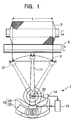
- a traverse device 1 comprises an arm (an oscillating member) 11, a voice coil motor 12, a control section 13, and a detection section 14.
- the traverse device 1 has no mechanical part such as a damper which determines a position where oscillation of the arm 11 is inverted, and a traverse range L is determined by oscillation of the arm 11 connected to the voice coil motor 12.
- a yarn Y traversed by the traverse device 1 is wound into a package 3 that is in contact with a rotatively driven friction drum 2.
- a yarn guide 21 for guiding the yarn Y is attached to a tip of the arm 11.
- the arm 11 has the other side or its intermediate portion connected to a shaft 22 so as to oscillate around the shaft 22.
- the arm 11 has the voice coil motor 12 connected to the other end thereof.
- the arm 11 constitutes an oscillating member having the yarn guide and connected to the voice coil motor 12 so as to be normally and reversely driven within a predetermined range.
- the voice coil motor (oscillating motor) 12 provided at the other end of the arm 11 and driven normally and reversely within a predetermined range comprises a stator 23 comprising a permanent magnet shaped like a fan extended around the shaft 22 and a movable member 24 provided to surround the stator 23 and comprising a fan-shaped air-core coil.
- the relationship between the stator 23 and the movable member 24 is similar to that between a magnet and a coil, and the movable member 24 is oscillated around the shaft 22 by means of a driving force exerted based on interactions between a current flowing through the coil and magnetic fields crossing the current.
- a permanent magnet surface of the stator 23 which is opposed to the movable member 24 has N or S poles contiguously disposed in a driving direction, compared to the other linear motors having N and S poles alternately disposed in the driving direction. Accordingly, when the movable member 24 is driven in one direction, the direction of a current flowing through a coil in the movable member 24 need not be switched.
- the movable member 24, which is driven normally and reversely within a range within which the stator 23 is present is supplied with power via flexible power-supplying line.
- the stator 23 may be a coil, while the movable member 24 may be a permanent magnet.
- the normal and reverse driving range of the movable member 24 is determined by a voltage supplied to the coil. Consequently, to change turn positions at traverse ends, a peak height (amplitude) of a triangular wave voltage supplied to the coil can be changed.
- the power supplied to the coil is not limited to the triangular wave voltage.
- the movable member 24 When the movable member 24 is constructed using the air-core coil, its weight can be reduced to allow the arm 11 to be inverted at a high speed.
- the stator 23 is shaped like a fan covering the normal and reverse driving range of the movable member 24 and the movable member 24 may be sized to move along the stator 23, the weight of the movable member 24 and this its inertia can be reduced, compared to motors that rotate through 360 degrees. As a result, the arm 11 can be inverted at a high speed when its direction is changed.
- the control section 13 has a servo function and outputs a command signal to the voice coil motor 12 to control oscillations effected by the voice coil motor 12.
- the control section 13 is provided for each voice coil motor 12.
- the detection section 14 detection means
- the control section 13 uses feedback control based on an output from the detection section 14 to arbitrarily control a position where and a time when an oscillation is effected by the voice coil motor 12.
- Figure 2 shows a specific example of the control section 13 including an analog servo function.
- the detection section 14 comprises a magneto-resistance element that varies a resistance value depending on the position of the movable member 24.
- a voltage corresponding to a difference between an output voltage value from the magneto-resistance element (detection section 14) and a command voltage value is output to the voice coil motor 12 through a comparator 26 and supplied to the coil (movable member 24) of the voice coil motor 12, which effects predetermined normal and reverse driving in a manner following the command value. That is, a current corresponding to the difference between the output voltage value from the detection section 14 and the command voltage value flows through the coil of the voice coil motor 12.
- control section 13 may include a digital servo function.
- the present invention is not limited to the feedback control, but open control can be employed where a spring is provided for the oscillating shaft so that its position is controlled while maintaining the balance with an urging force of the spring.
- Figure 3 is a graph showing an example of a command value output from the control section 13 in Figure 2.
- the command value is output as a triangular wave voltage.
- the height of the triangular wave determines the normal and reverse driving range of the voice coil motor 12, and the period of the triangular wave determines a speed at which the voice coil motor 12 is driven normally and reversely. This enables controlling of oscillating motions of the arm 11 connected to the voice coil motor 12.
- a current value is particularly high near a peak of the command value (near a position where the arm 11 is turned). This large variation in current induces braking before a turn as well as acceleration after a turn to enable the arm 11 to be inverted at a high speed without using an energy accumulating device against which the arm 11 collides.
- the control section 13 outputs a triangular wave of a predetermined height and a predetermined period to normally and reversely drive the voice coil motor 12 to traverse the yarn Y within the predetermined traverse range L, the yarn Y being guided by the yarn guide 21 disposed at the tip of the arm 11.
- the control section 13 provides such control that the triangular wave in Figure 3 has its height gradually reduced depending on the elapsed time or a measured yarn length. Accordingly, the traverse range L narrows gradually to allow a tapered-end package as shown in Figure 1 to be formed easily.
- a creeping operation of periodically or non-periodically mixing a lower triangular wave as shown by the alternate long and two short dashes line in Figure 3 can be performed to prevent saddle bag shapes from being formed at turn sections corresponding to opposite ends of the traverse range, thereby obtaining a package having a yarn layer with a straight surface.
- the voice coil motor 12 is structured to normally and reversely drive the arm 11 in a fashion tracing a fan around the shaft 22, the normal and reverse driving range is limited to enable the size and inertia of the motor to be reduced.
- the weights of the arm 11 and the yarn guide 21 disposed at the tip thereof are minimized to enable the arm 11 to be turned at a high speed.
- the above described traverse device with the single arm 11 is preferably applicable to a double twister or the like.
- the single arm type is also applicable to a spun yarn winder with a narrow traverse range.
- Figure 4 is a schematic structural drawing of another traverse device according to the present invention.
- four arms are arranged in juxtaposition in a traverse direction (an axial direction of a winding package) to accommodate high-speed traversing. Description of that part of the configuration of this traverse device which is common to the traverse device (single arm type) is omitted as appropriate.
- the traverse device 30 comprises units 31 and 32 for turning the yarn rightward or leftward and central units 33 and 34 for transferring the yarn.
- Each of the units 31 to 34 has an arm 35, a voice coil motor (an oscillating motor) 36, a control section 37, and a detection section 38.
- a main control section 39 controls the control sections 37, and each control section 37 controls a position where the arm 35 is oscillated, based on a command from the main control section 39.
- the control sections 37 and the main control section 39 constitute control means.
- the traverse device may comprise two or more units, for example, only the right and left units and one central unit.
- the yarn is transferred from the right to left units or from the left to right units at a point P1 between the units 31 and 33, a point P2 between the units 33 and 34, and a point P3 between the units 34 and 32.
- the arm 35 transfers the yarn during oscillation at the yarn transfer points P1, P2, and P3. That is, the delivering-side arm 35 stops the oscillation after transferring the yarn, and the receiving-side arm receives the yarn after starting oscillation. As a result, the yarn is transferred from the oscillating arm 35 to the subsequent oscillating arm 35, thereby allowing the yarn to be transferred at the points P1, P2, and P3 at a high speed.
- Appropriate guide plates are provided at the yarn transfer points P1, P2, and P3 to transfer the yarn from one yarn guide to another, but illustration thereof is omitted.
- the guide plates are each shaped to instantly receive the yarn from the delivering-side yarn guide and to transfer it to the receiving-side yarn guide.
- the present invention is not limited to the arm 35 that transfers the yarn during oscillation, but the delivering-side arm may stop at the transfer position, while the receiving-side arm may start oscillation at this transfer position, so that the yarn is transported over the total oscillating range of the plurality of arms.
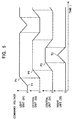
- Figure 5 is a graph showing timings in a command voltage generated by each control section 37 due to a command from the main control section 39 in Figure 4.
- each arm 35 lies leftward.
- the arm 35 of the left unit 31 oscillates rightward from a turn position T1 and transfers, at the point P2, the yarn to the arm 35 of the central unit 34.
- the arm 35 of the central unit 34 oscillates rightward and transfers, at the point P3, the yarn to the arm 35 of the right unit 32.
- the arm 35 of the right unit 32 moves to a turn position T2.
- the yarn is transferred from the turn position T2 to the turn position T1. Repeating the above operation allows the yarn Y to be traversed within the traverse range.
- the oscillation range of the arm 35 of each of the units 31 to 34 is narrowed to correspondingly enable the arm 35 to be shortened.
- inertia exerted during oscillation is diminished to enable the size of the entire traverse device to be reduced to accommodate high-speed turns.
- the length of the arm 35 of each of the right and left units 31 and 32 (this length equals the distance from the oscillating shaft to the yarn guide) can also be reduced below that of each of the central units 33 and 34 to accommodate high-speed turns. This reliably prevents saddle bag shapes from being formed at the right and left ends.
- a pattern of an increase or decrease in voltage at each of the units 31 to 34 can be individually varied to shift the yarn transfer points P1, P2, and P3 in the traverse direction (the axial direction of the package) to hinder straight winding at these points P1, P2, and P3.
- Figure 6 is a partial structural drawing of yet another traverse device.
- Two units 40 and 41 are stacked on each other (in the direction of the oscillating shaft) in a right and left portions where traversing is turned, so that the yarn is transferred between an upper arm 42 and a lower arm 43, which are overlapping each other.
- a guide plate (not shown in the drawing) can be provided as appropriate to reliably transfer the yarn from the upper arm 42 to the lower arm 43.
- the yarn traverse range is determined by the oscillating range of the oscillating member, which is in turn determined by the control means for controlling the voice coil motor.
- the traverse range can be gradually narrowed to easily wind the yarn into a tapered-end package or the traverse range can be periodically or non-periodically varied to carry out creeping to prevent saddle bag shapes.
- the present invention eliminates the needs for drive transmission means such as an endless belt to thereby improve durability while enabling the size of the entire traverse device to be reduced.
- the voice coil motor that is subjected to a small inertia and that can be switched between normal and reverse driving at a high speed serves to achieve high-speed turns to enable accurate formation of packages in a predetermined form such as a tapered end while preventing saddle bag shapes.
- the traverse range is divided into two or more so that the oscillating ranges of the two or more short oscillating members can be combined together to obtain a wide traverse range.
- the short oscillating members serve to reduce the inertia while increasing the turn speed, thereby enabling packages in an accurate form to be obtained while preventing saddle bag shapes.
- the number of oscillating members can be augmented to accommodate a wide traverse range.
- the detection means can be used for feedback control to accurately control the traverse turn positions. Additionally, if the yarn is transferred between the plurality of oscillating members, the yarn transfer positions can be accurately controlled. As a result, packages obtained have an appropriate winding form, and the yarn can be reliably transferred to prevent winding errors.
Landscapes
- Physics & Mathematics (AREA)
- Electromagnetism (AREA)
- Winding Filamentary Materials (AREA)
- Spinning Or Twisting Of Yarns (AREA)
Applications Claiming Priority (2)
| Application Number | Priority Date | Filing Date | Title |
|---|---|---|---|
| JP24702299 | 1999-09-01 | ||
| JP24702299A JP3292177B2 (ja) | 1999-09-01 | 1999-09-01 | トラバース装置 |
Publications (3)
| Publication Number | Publication Date |
|---|---|
| EP1081082A2 true EP1081082A2 (fr) | 2001-03-07 |
| EP1081082A3 EP1081082A3 (fr) | 2002-06-05 |
| EP1081082B1 EP1081082B1 (fr) | 2006-07-26 |
Family
ID=17157250
Family Applications (1)
| Application Number | Title | Priority Date | Filing Date |
|---|---|---|---|
| EP20000118313 Expired - Lifetime EP1081082B1 (fr) | 1999-09-01 | 2000-08-23 | Dispositif de va-et-vient |
Country Status (3)
| Country | Link |
|---|---|
| EP (1) | EP1081082B1 (fr) |
| JP (1) | JP3292177B2 (fr) |
| DE (1) | DE60029523T2 (fr) |
Cited By (7)
| Publication number | Priority date | Publication date | Assignee | Title |
|---|---|---|---|---|
| FR2826644A1 (fr) * | 2001-06-27 | 2003-01-03 | Rieter Icbt | Mecanisme de va et vient pour le bobinage de fils |
| WO2003020624A1 (fr) * | 2001-09-03 | 2003-03-13 | Sp. El. S.R.L. | Dispositif comportant un guide magnetique servant a enrouler un fil sur des supports cylindriques |
| DE102005022448A1 (de) * | 2005-05-14 | 2006-11-16 | Saurer Gmbh & Co. Kg | Fadenverlegeantrieb, insbesondere für eine Arbeitsstelle einer Textilmaschine |
| DE10152485B4 (de) * | 2001-10-24 | 2007-08-02 | Zimmer Ag | Changiervorrichtung |
| CN102745545A (zh) * | 2011-04-19 | 2012-10-24 | 村田机械株式会社 | 纱线卷绕机 |
| CN105151895A (zh) * | 2015-08-06 | 2015-12-16 | 浙江宏锋经纬编有限公司 | 一种纱筒收线装置 |
| CN112340532A (zh) * | 2020-03-31 | 2021-02-09 | 连江明杰信息技术有限公司 | 一种建筑施工收绳装置 |
Families Citing this family (6)
| Publication number | Priority date | Publication date | Assignee | Title |
|---|---|---|---|---|
| DE10009611A1 (de) * | 2000-02-29 | 2001-08-30 | Schlafhorst & Co W | Vorrichtung zur Steuerung der Fadenzugkraft eines laufenden Fadens in einer automatischen Wickeleinrichtung |
| JP2006335483A (ja) * | 2005-05-31 | 2006-12-14 | Murata Mach Ltd | 糸のトラバース装置、及びそれを備える繊維機械 |
| KR101329103B1 (ko) * | 2009-01-16 | 2013-11-14 | 티엠티 머시너리 가부시키가이샤 | 사조 권취 장치 및 방사기 |
| DE102014208336A1 (de) * | 2014-05-05 | 2015-11-05 | Schaeffler Technologies AG & Co. KG | Changierantrieb |
| CN109205385B (zh) * | 2018-07-24 | 2020-08-07 | 武汉船用机械有限责任公司 | 一种排管装置 |
| JP2020147382A (ja) * | 2019-03-11 | 2020-09-17 | 村田機械株式会社 | 糸巻取機、及び、糸巻取方法 |
Family Cites Families (4)
| Publication number | Priority date | Publication date | Assignee | Title |
|---|---|---|---|---|
| US5523911A (en) * | 1991-08-29 | 1996-06-04 | Hitachi Metals, Ltd. | Minimum bearing load, high precision actuator arm with force couple actuation |
| JPH08217332A (ja) * | 1995-02-16 | 1996-08-27 | Murata Mach Ltd | 糸のトラバース装置 |
| CH693094A5 (de) * | 1998-10-28 | 2003-02-28 | Rieter Ag Maschf | Changieraggregat. |
| DE19858548A1 (de) * | 1998-12-18 | 2000-06-21 | Schlafhorst & Co W | Fadenführer zum traversierenden Zuführen eines Fadens zu einer rotierend angetriebenen Auflaufspule |
-
1999
- 1999-09-01 JP JP24702299A patent/JP3292177B2/ja not_active Expired - Fee Related
-
2000
- 2000-08-23 DE DE2000629523 patent/DE60029523T2/de not_active Expired - Lifetime
- 2000-08-23 EP EP20000118313 patent/EP1081082B1/fr not_active Expired - Lifetime
Cited By (10)
| Publication number | Priority date | Publication date | Assignee | Title |
|---|---|---|---|---|
| FR2826644A1 (fr) * | 2001-06-27 | 2003-01-03 | Rieter Icbt | Mecanisme de va et vient pour le bobinage de fils |
| WO2003002443A1 (fr) * | 2001-06-27 | 2003-01-09 | Rieter Icbt | Mecanisme de va et vient pour le bobinage de fils |
| WO2003020624A1 (fr) * | 2001-09-03 | 2003-03-13 | Sp. El. S.R.L. | Dispositif comportant un guide magnetique servant a enrouler un fil sur des supports cylindriques |
| DE10152485B4 (de) * | 2001-10-24 | 2007-08-02 | Zimmer Ag | Changiervorrichtung |
| DE102005022448A1 (de) * | 2005-05-14 | 2006-11-16 | Saurer Gmbh & Co. Kg | Fadenverlegeantrieb, insbesondere für eine Arbeitsstelle einer Textilmaschine |
| CN102745545A (zh) * | 2011-04-19 | 2012-10-24 | 村田机械株式会社 | 纱线卷绕机 |
| CN102745545B (zh) * | 2011-04-19 | 2016-05-25 | 村田机械株式会社 | 纱线卷绕机 |
| CN105151895A (zh) * | 2015-08-06 | 2015-12-16 | 浙江宏锋经纬编有限公司 | 一种纱筒收线装置 |
| CN105151895B (zh) * | 2015-08-06 | 2017-12-08 | 盐城金大纺织机械制造有限公司 | 一种纱筒收线装置 |
| CN112340532A (zh) * | 2020-03-31 | 2021-02-09 | 连江明杰信息技术有限公司 | 一种建筑施工收绳装置 |
Also Published As
| Publication number | Publication date |
|---|---|
| DE60029523T2 (de) | 2007-08-09 |
| EP1081082B1 (fr) | 2006-07-26 |
| DE60029523D1 (de) | 2006-09-07 |
| EP1081082A3 (fr) | 2002-06-05 |
| JP2001072334A (ja) | 2001-03-21 |
| JP3292177B2 (ja) | 2002-06-17 |
Similar Documents
| Publication | Publication Date | Title |
|---|---|---|
| EP1081082A2 (fr) | Dispositif et procédé de va-et-vient | |
| US6311919B1 (en) | Yarn guide for the traversing delivery of a yarn to a rotationally driven takeup bobbin | |
| JP4155705B2 (ja) | 糸を移す方法及び綾振り装置 | |
| US6592066B1 (en) | Thread guide for traversing a thread in a rotating winding bobbin | |
| CN1332867C (zh) | 横动控制装置 | |
| EP2765102B1 (fr) | Procédé de distribution de fil enroulé et dispositif pour sa mise en oeuvre | |
| JPH10129931A (ja) | 糸巻取り装置 | |
| CN1702031B (zh) | 一种驱动形成交叉卷绕筒子的纺织机的卷绕装置的方法和装置 | |
| JP2002528358A (ja) | 糸トラバース装置 | |
| EP0066128B1 (fr) | Dispositif pour la formation de paquets de fil | |
| JP6490072B2 (ja) | 綾振りユニットおよび綾振りユニットの制御方法 | |
| US4128988A (en) | Apparatus for twisting and winding strand material | |
| ITMI20061354A1 (it) | Dispositivo guadafilo ad alta frequenza per la produzione di rocche a zettatura modulata | |
| CN105517931B (zh) | 敷纱设备和络筒机 | |
| JP2003012228A (ja) | 正逆トラバース装置及び正逆トラバース方法 | |
| JP2001261234A (ja) | トラバース装置及びトラバース方法 | |
| JPH02110062A (ja) | ウエブ内張力の制御装置 | |
| CN108290699B (zh) | 用于在织机中供应纬纱的受控系统 | |
| JPH02118401A (ja) | 角変換器 | |
| JPH07137935A (ja) | 連続往復移動装置 | |
| JPH0477547B2 (fr) | ||
| SE516603C2 (sv) | Förfarande och anordning för att längdmäta och magasinera tråd vid väv- eller textilmaskiner | |
| KR20220033452A (ko) | 실 권취기 | |
| ITVI20000161A1 (it) | Dispositivo per l'avvolgimento su una rocca di uno o piu' fili | |
| JPH07297065A (ja) | 間欠送り整列巻線機 |
Legal Events
| Date | Code | Title | Description |
|---|---|---|---|
| PUAI | Public reference made under article 153(3) epc to a published international application that has entered the european phase |
Free format text: ORIGINAL CODE: 0009012 |
|
| AK | Designated contracting states |
Kind code of ref document: A2 Designated state(s): AT BE CH CY DE DK ES FI FR GB GR IE IT LI LU MC NL PT SE |
|
| AX | Request for extension of the european patent |
Free format text: AL;LT;LV;MK;RO;SI |
|
| PUAL | Search report despatched |
Free format text: ORIGINAL CODE: 0009013 |
|
| AK | Designated contracting states |
Kind code of ref document: A3 Designated state(s): AT BE CH CY DE DK ES FI FR GB GR IE IT LI LU MC NL PT SE |
|
| AX | Request for extension of the european patent |
Free format text: AL;LT;LV;MK;RO;SI |
|
| 17P | Request for examination filed |
Effective date: 20020916 |
|
| AKX | Designation fees paid |
Designated state(s): DE IT |
|
| 17Q | First examination report despatched |
Effective date: 20030617 |
|
| GRAP | Despatch of communication of intention to grant a patent |
Free format text: ORIGINAL CODE: EPIDOSNIGR1 |
|
| RTI1 | Title (correction) |
Free format text: TRAVERSE DEVICE |
|
| GRAS | Grant fee paid |
Free format text: ORIGINAL CODE: EPIDOSNIGR3 |
|
| GRAA | (expected) grant |
Free format text: ORIGINAL CODE: 0009210 |
|
| AK | Designated contracting states |
Kind code of ref document: B1 Designated state(s): DE IT |
|
| REF | Corresponds to: |
Ref document number: 60029523 Country of ref document: DE Date of ref document: 20060907 Kind code of ref document: P |
|
| PLBE | No opposition filed within time limit |
Free format text: ORIGINAL CODE: 0009261 |
|
| STAA | Information on the status of an ep patent application or granted ep patent |
Free format text: STATUS: NO OPPOSITION FILED WITHIN TIME LIMIT |
|
| 26N | No opposition filed |
Effective date: 20070427 |
|
| PGFP | Annual fee paid to national office [announced via postgrant information from national office to epo] |
Ref country code: IT Payment date: 20090820 Year of fee payment: 10 |
|
| PG25 | Lapsed in a contracting state [announced via postgrant information from national office to epo] |
Ref country code: IT Free format text: LAPSE BECAUSE OF NON-PAYMENT OF DUE FEES Effective date: 20100823 |
|
| PGFP | Annual fee paid to national office [announced via postgrant information from national office to epo] |
Ref country code: DE Payment date: 20120822 Year of fee payment: 13 |
|
| PG25 | Lapsed in a contracting state [announced via postgrant information from national office to epo] |
Ref country code: DE Free format text: LAPSE BECAUSE OF NON-PAYMENT OF DUE FEES Effective date: 20140301 |
|
| REG | Reference to a national code |
Ref country code: DE Ref legal event code: R119 Ref document number: 60029523 Country of ref document: DE Effective date: 20140301 |