EP1081084B1 - Articulation pour un disposif de levage tracté sur un bras porteur - Google Patents
Articulation pour un disposif de levage tracté sur un bras porteur Download PDFInfo
- Publication number
- EP1081084B1 EP1081084B1 EP00118724A EP00118724A EP1081084B1 EP 1081084 B1 EP1081084 B1 EP 1081084B1 EP 00118724 A EP00118724 A EP 00118724A EP 00118724 A EP00118724 A EP 00118724A EP 1081084 B1 EP1081084 B1 EP 1081084B1
- Authority
- EP
- European Patent Office
- Prior art keywords
- profiled element
- bendable
- profiled
- joint
- movable
- Prior art date
- Legal status (The legal status is an assumption and is not a legal conclusion. Google has not performed a legal analysis and makes no representation as to the accuracy of the status listed.)
- Expired - Lifetime
Links
- 238000005452 bending Methods 0.000 claims description 4
- 210000003127 knee Anatomy 0.000 description 2
- 230000008878 coupling Effects 0.000 description 1
- 238000010168 coupling process Methods 0.000 description 1
- 238000005859 coupling reaction Methods 0.000 description 1
- 238000007689 inspection Methods 0.000 description 1
- 238000000034 method Methods 0.000 description 1
- 210000003857 wrist joint Anatomy 0.000 description 1
Images


Classifications
-
- B—PERFORMING OPERATIONS; TRANSPORTING
- B66—HOISTING; LIFTING; HAULING
- B66B—ELEVATORS; ESCALATORS OR MOVING WALKWAYS
- B66B9/00—Kinds or types of lifts in, or associated with, buildings or other structures
- B66B9/16—Mobile or transportable lifts specially adapted to be shifted from one part of a building or other structure to another part or to another building or structure
Definitions
- the invention relates to a folding device for a mobile mobile working device, in particular elevator device, to be transported with a trailer hitch unit, which is arranged in particular on an arm boom, and that at least comprises a profile element in which at least a telescopic rod element is arranged.
- An implement is from the earlier priority registration DE-A-198 90 332 known.
- a drawbar unit is arranged on the arm boom, which has a drawbar holding unit with a Drawbar holding a towbar unit a tiller arm with at least one fixing unit with connected to a locking bolt and a coupling joint is.
- this implement is provided with a buckling piece, such as it is known for an inclined lift from DE-A-197 03 158 is the haulage obstructed the towing vehicle during the Transport of the implement.
- the advantages achieved by the invention are in particular in that the folding folding unit in the transport state the profile element is fixed and the Schiebeknickisme is in the profile element. This disturbs the folding buckle unit and the sliding-buckling unit does not move of the towing vehicle. Extended when taking on the job the folding buckle unit the profile element. The sliding bending unit, which was folded back in the transport state, ensures that it passes over the folding buckling unit that the extended telescopic rod element as before opposite Adjust the arm boom accordingly. By the so-formed double-kinking unit is secured, that continue the whole valuable length of the elevator device is available and used the elevator device so can be, as is the case with other elevator facilities the case is.
- This kink device can with any work tool, in particular Elevator device, are used, regardless of whether the drawbar arranged on the arm boom or directly on the vehicle is.
- the joint intermediate profile element and the extension profile element are at least partially compatible with each other. Both are also compatible with the profile element. hereby is secured in the extended state of the folding buckle unit, that this represents an extension of the profile element.
- the joint intermediate profile element can by the first and a third articulated joint element with the profile element and through the second and a fourth articulated joint element with the extension profile element be connected. This is the mobility the parts of the folding buckle secured.
- the joint intermediate profile element can on both sides and the Arm boom profile at the end and the extension profile element at the end pointing to the joint intermediate profile element at least be partially provided with a profile bevel, that in the extended state of the folding buckling unit in the Working position KnickausEnglishept at least partially form are.
- These kinking recesses allow angling the extended telescopic rod member relative to the Profile element.
- the sliding unit can be designed differently, as the conditions of use demand. So she can make two consist of opposite sliding intermediate elements, through the first and a third intermediate articulated joint element with the first part sliding profile element and by the second and a fourth intermediate joint element with the second partial sliding profile element can be connected.
- the two sliding intermediate elements can be connected by at least one linkage.
- the linkage can from two the respective sliding intermediate elements connecting link rods and another link rod exist that the two sliding intermediate profile elements combines. But it is possible, the two sliding intermediate profile elements to connect with only a single rod.
- the two partial sliding profile elements of the sliding profile element can be moved like a telescopic rod element be. This is a simple and secure function when Moving the Schiebeknickiser ensured.
- a roller profile element be connected to a pulley, around a rope to lead is.
- the roller profile element with the deflection roller can before the Klappknickmaschine be arranged. This ensures that that the folding buckle unit folded on the arm boom profile can be.
- the Schiebeknick nie can in the transport state behind and in working condition in front of the roller profile element with the deflection roller be postioned. This allows the folding folding unit to the desired position.
- the profile element may be the arm boom profile.
- the telescopic rod element In him at least the telescopic rod element can be arranged. In the transport state, it can with the chassis to a Chassis connected. At him also the An vonrkupplungseiheit can who are in a transport and working position can be adjusted.
- the profile element can also be another telescopic rod profile element be.
- the folding folding unit and the sliding folding unit can the arm boom profile and / or each of the Telescopic rod elements are assigned, so that one and if necessary, several kinks on the most diverse Jobs can be realized.
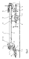
- FIG. 1 shows an inclined lift
- the arm boom profile 2 are telescopic rod elements 6.1, 6.2, ..., 6.n.
- a wrist joint 11 At the opposite End is through a wrist joint 11 'a Einachsfahrgestell 5 attached to the arm boom profile.
- a working hydraulic cylinder 12 Between the Einachsfahrgestell 5 and the arm boom profile. 2 is a working hydraulic cylinder 12 'arranged with a check valve.
- a bolt connection 13 With the help of a bolt connection 13 'is the arm boom profile 2 and the Einachsfahrgestell 5 to a chassis. 3 connect to.
- the Einachsfahrgestell is provided with wheels 17 and has front supports 8 and rear supports 9.
- On the arm boom profile 2 is a load carriage 10 in the transport state stalled.
- the drawbar unit 1 consists of a drawbar linkage 12, via a drawbar holding unit 13 with the arm boom profile 2 connected in a transport and a working position is. On drawbar linkage a creatable support wheel 11 is attached. At the end of the telescopic rod element 6.2 is a support wheel unit 14 arranged.
- the elevator device shown in FIG. 1 is located in FIG a transport position.
- this transport position is a arranged at the end of the telescopic rod element 6.2 folding folding unit 4 a buckling device on the arm boom profile 2 and / or the telescopic rod elements 6.2, ... lying positioned.
- this lying position it disturbs a traction device, z. B. a car, not in the process of the elevator device, especially when tightly hitting the drawbar opposite the elevator.
- TÜV Technical Inspection Association
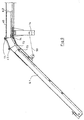
- the folding-folding unit 4 is of the Transport- folded into a working position shown.
- the folding-folding unit 4 consists of an Armverinrungsprofilelement 41 and one between the Armverinrungsprofil 41 and the end of the telescopic rod member 6.2 arranged Gelenk formatprofilelement 42.
- the arm boom profile element 41, the joint intermediate profile element 42 and the telescopic rod element 6.2 compatible with each other. This ensures that that the Armverinrungsprofilement 41 and the joint intermediate profile element 42 an extension of the telescopic rod element 6.2 realize.
- the hinge intermediate profile element 42 is connected to the Armverinrungsprofilelement 41 by an articulated element 43 and a Articulated element 45 connected.
- the end of the arm boom profile 2 is the Gelenkzwichenprofilelement 42 by an articulated joint element 44 and by an articulated member 46th connected.
- the joint intermediate profile element 42 is on both sides and the Armverinrungsprofilelement 41 and the telescopic rod element 6.2 provided on one side with Profilabschrägungen. in the extended state, as shown in Figure 2, As a result, bending recesses 48 are formed.
- a buckling hydraulic cylinder element 50 is arranged, which is indicated by the dashed line. At Location of the hydraulic cylinder 50 may also be another adjustment are used, e.g. a rack, Hoist winch or the like.
- the sliding knee element 7 consists of two opposite Sliding intermediate elements 72, which by embknickgelenkiata 73 and 75 with a partial sliding profile element 40.1 and with intermediate articulation elements 74 and 76 with a partial sliding profile element 40.2 are hingedly connected.
- the sliding intermediate elements 72 can be used as flat profiles, pipes or be formed. Between the sliding intermediate elements 72 is a linkage 71, the consists of two articulated rods, each with the intermediate articulation elements are connected. To the stability of the whole Systems connects another rod the two sliding intermediate elements 72nd
- roller profile element 18 As particularly shown in FIG. 6, is located in front of the sliding bending unit 7 a roller profile element 18 with a deflection roller 15, around which a rope 16 is guided.
- the roller profile element 18 is in the range of the telescopic rod profile element 6.2 positioned.
- Figures 7 and 8 is shown how with the help of the shifting of the sliding profile element 40, the Schiebeknickiser 7, which was still behind the deflection roller 15 in FIG. before it is pushed over the Klappknickmaschine 4. in this connection come, in particular Figure 8 shows, substantially the intermediate joint elements 73, 74, 75, 76 via the articulated elements 43, 44, 45, 46 to lie, so that the buckling device is realized in the form of a double fold.
- Figures 5 and 6 is the telescopic rod element 6.1 still in the telescopic rod element 6.2.
- Figures 7 and 8 it is shown pushed out of this and can be opposite be adjusted as shown in Figure 9.
- the elevator device consists of a boom arm profile 2, and only one telescopic rod element 6.1, here is the Klappknickiki 4 here positioned on the arm boom profile 2.
- the folding boom unit 2 is attached to the boom arm profile 2 4 with its joint intermediate profile element 42 and before the arm extension profile element 41, as already described, connected via the articulated elements 43, 44, 45, 46.
- the Armverinrungsprofilelement and the joint intermediate profile element 42 with the aid of Knickhydraulikzylinderelements 15 in the extended state brought as shown in particular in Figure 2.
- the Armverinrungsprofilelement 41 and the Joint intermediate profile element 42 a valuable extension of the telescopic rod element 6.2.
- the roller profile element 18 with the guide roller 15 has the Position, as shown in particular in Figure 6. In this position is the Schiebeknickiki 7 behind the Folding folding unit 4. Subsequently, the telescopic rod element 6.1 extended and then or with the telescopic rod element 6.1 at the same time the Schiebeknickiser 7 in Direction folding folding unit 4 shifted. By advancing the two partial sliding profile elements 40.1 and 40.2 comes so finally the Schiebeknickiser 7 on the Klappknikkü 4 to lie. This is the profile element 40.2 behind the roller profile element 18 with the guide roller 15th and the partial sliding profile element 40.1 in front.
- Has the Schiebeknickiser 7 this position relative to the Klappknicktechnik 4 reached, can by pressing the Knickhydraulikzylinderelements 15 the extended telescopic rod element 6.1 relative to the telescopic rod element 6.2 be adjusted and thus bent. By adjusting the two buckling recesses 48 are closed and thereby reached the kinking position. By pressing the Knickhydraulikzylinderelements 15 can also be a Abknickwinkel greater than that shown in FIG. 9 is.
- the difference in height is due an extension of the other telescopic elements bridged so that the load carriage 10, starting from the end of the arm boom profile 2 up to the top over the double folds 4, 7 away on the roof or another sloping Area can be moved.
Landscapes
- Engineering & Computer Science (AREA)
- Structural Engineering (AREA)
- Civil Engineering (AREA)
- Transportation (AREA)
- Automation & Control Theory (AREA)
- Jib Cranes (AREA)
- Forklifts And Lifting Vehicles (AREA)
- Chain Conveyers (AREA)
- Automatic Assembly (AREA)
- Steering Controls (AREA)
Claims (12)
- Appareillage mobile tracté, en particulier équipement de levage à dispositif articulé, qui est destiné à être transporté au moyen d'une unité d'accouplement (11, 12, 13 14) de remorque, en pa,rticulier montée sur un profilé (2) de bras porteur, et comprend au moins un élément profilé (2, 6.2) dans lequel au moins un élément de tige télescopique (6.1, ... , 6.n) est monté de manière télescopique, dans lequel:l'élément profilé (2, 6.2) porte une unité d'articulation repliable (4) qui y est montée etqui se compose d'un élément profilé intermédiaire (42) de joint, qui est connecté à une première extrémité de l'élément profilé (2, 6.2) par un premier élément (44, 46) de joint articulé et qui est monté au moins sur un élément profilé (41) de prolongement au moyen d'un deuxième élément (43, 45) de joint articulé,d'une manière telle que l'élément profilé intermédiaire (42) de joint et l'élément profilé (41) de prolongement de bras sont appliqués sur l'élément profilé (2, 6.2) dans l'état de transport,dans l'élément profilé (2, 6.2) coulisse un élément profilé coulissant (40) dans lequel est montée une unité d'articulation coulissante (7),qui se compose d'au moins un élément profilé coulissant (72) qui est connecté par une première extrémité au moyen d'un premier élément intermédiaire (73, 75) de joint articulé à un premier élément de profilé coulissant partiel (40.1) et qui est connecté par son extrémité opposée au moyen d'un deuxième élément intermédiaire (74, 76) de joint articulé à un deuxième élément profilé coulissant partiel (40.2), etdans l'état de travail;l'élément profilé intermédiaire (42) de joint et l'élément profilé de prolongement (41) de l'unité d'articulation repliable (4) sont reçus par l'élément profilé (2, 6.2) et sont disposés dans le prolongement de l'élément profilé (2, 6.2),l'élément de tige télescopique (6.1) est coulissé hors de l'élément profilé (2, 6.2) et au-dessus de l'unité d'articulation repliable (4), etl'unité d'articulation coulissante (7) est coulissée au-dessus de l'unité d'articulation repliable (4) d'une manière telle que l'élément de tige télescopique (6.1) est déplacé par rapport à l'élément profilé (2, 6.2) de manière à entrer dans les éléments de joints articulés (43, 44, 45, 46) et dans les éléments intermédiaires de joints articulés (73, 74, 75, 76).
- Appareillage selon la revendication 1, caractérisé en ce que l'élément profilé intermédiaire (42) de joint et l'élément profilé de prolongement (41) sont configurés de manière à être au moins partiellement compatibles entre eux et au moins partiellement compatibles avec l'élément profilé (2, 6.2).
- Appareillage selon la revendication 1 ou 2, caractérisé en ce que l'élément profilé intermédiaire (42) de joint est connecté par le premier et un troisième éléments de joints articulés (44, 46) à l'élément profilé (2, 6.2) et est connecté par le deuxième et un quatrième éléments de joints articulés (43, 45) avec l'élément profilé de prolongement (41).
- Appareillage selon l'une quelconque des revendications précédentes, caractérisé en ce que l'élément profilé intermédiaire (42) de joint comporte sur les deux côtés un chanfrein et que des profils chanfreinés (47) sont formés au moins partiellement sur l'élément profilé (2, 6.2) à son extrémité et sur le profilé de prolongement (41) à l'extrémité tournée vers l'élément profilé intermédiaire (42) de joint, de manière à former au moins partiellement des évidements d'articulation (48) dans l'état d'extension de l'unité d'articulation repliable (4) dans sa position de travail.
- Appareillage selon l'une quelconque des revendications précédentes, caractérisé en ce que l'unité d'articulation coulissante (7) se compose de deux éléments intermédiaires coulissants opposés l'un à l'autre (72), qui sont connectés par le premier et un troisième éléments intermédiaires de joint articulé (73, 75) au premier élément profilé coulissant partiel (40.1) et sont connectés par le deuxième et un quatrième éléments intermédiaires de joint articulé (74, 76) au deuxième élément profilé coulissant partiel (40.2).
- Appareillage selon la revendication 5, caractérisé en ce que les deux éléments profilés intermédiaires coulissants (72) sont connectés par au moins des trigles (71) de joint.
- Appareillage selon l'une quelconque des revendications précédentes, caractérisé en ce que les deux éléments profilés coulissants partiels (40.1, 40.2) de l'élément profilé coulissant (40) peuvent coulisser à la manière d'un élément de tige télescopique (6.1, ... 6.n).
- Appareillage selon l'une quelconque des revendications précédentes, caractérisé en ce qu'un élément profilé (18) à rouleau, qui inclut un rouleau (15) de changement de direction autour duquel est guidée une corde (16), est positionné au moins partiellement dans la zone de l'élément profilé (2, 6.2).
- Appareillage selon l'une quelconque des revendications précédentes, caractérisé en ce que l'élément profilé (18) à rouleau qui inclut le rouleau (15) de changement de direction est monté devant l'unité d'articulation repliable (4).
- Appareillage selon l'une quelconque des revendications précédentes, caractérisé en ce que l'unité d'articulation coulissante (7) est positionnée, dans l'état de transport, derrière l'élément profilé (18) à rouleau qui inclut le rouleau (15) de changement de direction et est positionnée, dans l'état de travail, devant cet élément profilé.
- Appareillage selon l'une quelconque des revendications précédentes, caractérisé en ce que l'élément profilé est le profilé (2) de bras porteur,
dans lequel est monté au moins l'élément de tige télescopique (6.1, ...),
qui est connecté dans l'état de transport avec un élément (5) en forme de chariot pour constituer un châssis (3) et
sur lequel l'unité d'accouplement (11, 12, 13, 14) de remorque doit être placée dans la position de transport et la position de travail. - Appareillage selon l'une quelconque des revendications précédentes, caractérisé en ce que l'élément profilé est un autre des éléments (6.2, ... , 6.n) de tige télescopique, qui est monté de manière télescopique dans le profilé (2) de bras porteur.
Applications Claiming Priority (2)
| Application Number | Priority Date | Filing Date | Title |
|---|---|---|---|
| DE29915566U | 1999-09-04 | ||
| DE29915566U DE29915566U1 (de) | 1999-09-04 | 1999-09-04 | Knickvorrichtung für eine am Armausleger gezogene Aufzugseinrichtung |
Publications (3)
| Publication Number | Publication Date |
|---|---|
| EP1081084A2 EP1081084A2 (fr) | 2001-03-07 |
| EP1081084A3 EP1081084A3 (fr) | 2002-04-10 |
| EP1081084B1 true EP1081084B1 (fr) | 2005-10-19 |
Family
ID=8078465
Family Applications (1)
| Application Number | Title | Priority Date | Filing Date |
|---|---|---|---|
| EP00118724A Expired - Lifetime EP1081084B1 (fr) | 1999-09-04 | 2000-08-30 | Articulation pour un disposif de levage tracté sur un bras porteur |
Country Status (3)
| Country | Link |
|---|---|
| EP (1) | EP1081084B1 (fr) |
| AT (1) | ATE307083T1 (fr) |
| DE (2) | DE29915566U1 (fr) |
Family Cites Families (2)
| Publication number | Priority date | Publication date | Assignee | Title |
|---|---|---|---|---|
| FR2365020A1 (fr) * | 1976-09-20 | 1978-04-14 | Roodt Guy | Dispositif d'articulation pour echelles |
| DE3914484A1 (de) * | 1989-05-02 | 1990-11-08 | Boecker Albert Gmbh & Co Kg | Aus mehreren teleskopschuessen bestehender schraegaufzug |
-
1999
- 1999-09-04 DE DE29915566U patent/DE29915566U1/de not_active Expired - Lifetime
-
2000
- 2000-08-30 AT AT00118724T patent/ATE307083T1/de not_active IP Right Cessation
- 2000-08-30 DE DE50011359T patent/DE50011359D1/de not_active Expired - Lifetime
- 2000-08-30 EP EP00118724A patent/EP1081084B1/fr not_active Expired - Lifetime
Also Published As
| Publication number | Publication date |
|---|---|
| DE29915566U1 (de) | 2000-02-17 |
| EP1081084A2 (fr) | 2001-03-07 |
| DE50011359D1 (de) | 2006-03-02 |
| ATE307083T1 (de) | 2005-11-15 |
| EP1081084A3 (fr) | 2002-04-10 |
Similar Documents
| Publication | Publication Date | Title |
|---|---|---|
| EP2998264B1 (fr) | Mât en treillis haubanés latéralement | |
| EP1308075B1 (fr) | Aide et méthode pour accoupler un outil ou une remorque avec un timon à un tracteur | |
| DE1481873A1 (de) | Lasthebevorrichtung | |
| EP1961691B1 (fr) | Appareil de transbordement | |
| DE4413444A1 (de) | Laderampe für Kraftfahrzeuge | |
| DE102007039933B4 (de) | Rungenstock | |
| EP0564403B1 (fr) | Dispositif de chargement et de déchargement d'un porte-charges sur un véhicule | |
| EP1077306A2 (fr) | Machine de travaux mobile | |
| EP1081084B1 (fr) | Articulation pour un disposif de levage tracté sur un bras porteur | |
| DE3822542A1 (de) | Ladeanhaenger | |
| DE3625297C2 (fr) | ||
| DE10007773A1 (de) | Kran mit einem Teleskopausleger | |
| DE10139393C1 (de) | Zweiwegefahrzeugkran zum kombinierten Straßen- und Schieneneinsatz sowie Aufgleisverfahren | |
| DE1658621A1 (de) | Kraftfahrzeug mit einer Vorrichtung zum Transportieren und Verlegen einer mit Auffahrrampen versehenen Klappbruecke | |
| DE2908237C2 (de) | Mobiler Drehkran | |
| DE29920153U1 (de) | Schwellengreifer | |
| DE1780141C3 (de) | Zusammenschiebbares Verdeck, insbesondere für Lastkraftwagen und -anhänger | |
| DE2522390C2 (de) | Knickausleger eines Fahrzeugkranes | |
| DE102008007715A1 (de) | Ausleger eines Brückenverlegefahrzeuges und Verfahren zur Bewegung eines Auslegers in eine Fahrzeugtransportstellung | |
| EP0631975B1 (fr) | Accessoire en particulier pour chariot élévateur | |
| DE3807666C1 (en) | Tramway transport device | |
| EP4053066B1 (fr) | Dispositif et procédé de montage / démontage d'une flèche de grue mobile | |
| EP0135703B1 (fr) | Châssis amovible monté sur un chariot roulant sur les rails d'un monte-charge incliné | |
| EP0940364A2 (fr) | Ascenseur de construction déplaçable | |
| DE102005045264B4 (de) | Vorrichtung zum Verbinden von Chassis und Karosserie bei der Montage eines Kraftfahrzeugs |
Legal Events
| Date | Code | Title | Description |
|---|---|---|---|
| PUAI | Public reference made under article 153(3) epc to a published international application that has entered the european phase |
Free format text: ORIGINAL CODE: 0009012 |
|
| AK | Designated contracting states |
Kind code of ref document: A2 Designated state(s): AT BE CH CY DE DK ES FI FR GB GR IE IT LI LU MC NL PT SE |
|
| AX | Request for extension of the european patent |
Free format text: AL;LT;LV;MK;RO;SI |
|
| PUAL | Search report despatched |
Free format text: ORIGINAL CODE: 0009013 |
|
| AK | Designated contracting states |
Kind code of ref document: A3 Designated state(s): AT BE CH CY DE DK ES FI FR GB GR IE IT LI LU MC NL PT SE |
|
| AX | Request for extension of the european patent |
Free format text: AL;LT;LV;MK;RO;SI |
|
| RIC1 | Information provided on ipc code assigned before grant |
Free format text: 7B 66B 9/16 A, 7B 66B 9/193 B |
|
| 17P | Request for examination filed |
Effective date: 20020612 |
|
| AKX | Designation fees paid |
Free format text: AT BE CH CY DE DK ES FI FR GB GR IE IT LI LU MC NL PT SE |
|
| GRAP | Despatch of communication of intention to grant a patent |
Free format text: ORIGINAL CODE: EPIDOSNIGR1 |
|
| GRAS | Grant fee paid |
Free format text: ORIGINAL CODE: EPIDOSNIGR3 |
|
| GRAA | (expected) grant |
Free format text: ORIGINAL CODE: 0009210 |
|
| AK | Designated contracting states |
Kind code of ref document: B1 Designated state(s): AT BE CH CY DE DK ES FI FR GB GR IE IT LI LU MC NL PT SE |
|
| PG25 | Lapsed in a contracting state [announced via postgrant information from national office to epo] |
Ref country code: FI Free format text: LAPSE BECAUSE OF FAILURE TO SUBMIT A TRANSLATION OF THE DESCRIPTION OR TO PAY THE FEE WITHIN THE PRESCRIBED TIME-LIMIT Effective date: 20051019 Ref country code: NL Free format text: LAPSE BECAUSE OF FAILURE TO SUBMIT A TRANSLATION OF THE DESCRIPTION OR TO PAY THE FEE WITHIN THE PRESCRIBED TIME-LIMIT Effective date: 20051019 Ref country code: GB Free format text: LAPSE BECAUSE OF FAILURE TO SUBMIT A TRANSLATION OF THE DESCRIPTION OR TO PAY THE FEE WITHIN THE PRESCRIBED TIME-LIMIT Effective date: 20051019 Ref country code: IE Free format text: LAPSE BECAUSE OF FAILURE TO SUBMIT A TRANSLATION OF THE DESCRIPTION OR TO PAY THE FEE WITHIN THE PRESCRIBED TIME-LIMIT Effective date: 20051019 |
|
| REG | Reference to a national code |
Ref country code: GB Ref legal event code: FG4D Free format text: NOT ENGLISH |
|
| REG | Reference to a national code |
Ref country code: CH Ref legal event code: EP |
|
| REG | Reference to a national code |
Ref country code: IE Ref legal event code: FG4D Free format text: LANGUAGE OF EP DOCUMENT: GERMAN |
|
| PG25 | Lapsed in a contracting state [announced via postgrant information from national office to epo] |
Ref country code: SE Free format text: LAPSE BECAUSE OF FAILURE TO SUBMIT A TRANSLATION OF THE DESCRIPTION OR TO PAY THE FEE WITHIN THE PRESCRIBED TIME-LIMIT Effective date: 20060119 Ref country code: DK Free format text: LAPSE BECAUSE OF FAILURE TO SUBMIT A TRANSLATION OF THE DESCRIPTION OR TO PAY THE FEE WITHIN THE PRESCRIBED TIME-LIMIT Effective date: 20060119 Ref country code: GR Free format text: LAPSE BECAUSE OF FAILURE TO SUBMIT A TRANSLATION OF THE DESCRIPTION OR TO PAY THE FEE WITHIN THE PRESCRIBED TIME-LIMIT Effective date: 20060119 |
|
| PG25 | Lapsed in a contracting state [announced via postgrant information from national office to epo] |
Ref country code: ES Free format text: LAPSE BECAUSE OF FAILURE TO SUBMIT A TRANSLATION OF THE DESCRIPTION OR TO PAY THE FEE WITHIN THE PRESCRIBED TIME-LIMIT Effective date: 20060130 |
|
| REF | Corresponds to: |
Ref document number: 50011359 Country of ref document: DE Date of ref document: 20060302 Kind code of ref document: P |
|
| PG25 | Lapsed in a contracting state [announced via postgrant information from national office to epo] |
Ref country code: PT Free format text: LAPSE BECAUSE OF FAILURE TO SUBMIT A TRANSLATION OF THE DESCRIPTION OR TO PAY THE FEE WITHIN THE PRESCRIBED TIME-LIMIT Effective date: 20060320 |
|
| NLV1 | Nl: lapsed or annulled due to failure to fulfill the requirements of art. 29p and 29m of the patents act | ||
| GBV | Gb: ep patent (uk) treated as always having been void in accordance with gb section 77(7)/1977 [no translation filed] |
Effective date: 20051019 |
|
| REG | Reference to a national code |
Ref country code: IE Ref legal event code: FD4D |
|
| REG | Reference to a national code |
Ref country code: FR Ref legal event code: CA |
|
| ET | Fr: translation filed | ||
| PLBE | No opposition filed within time limit |
Free format text: ORIGINAL CODE: 0009261 |
|
| STAA | Information on the status of an ep patent application or granted ep patent |
Free format text: STATUS: NO OPPOSITION FILED WITHIN TIME LIMIT |
|
| PG25 | Lapsed in a contracting state [announced via postgrant information from national office to epo] |
Ref country code: LI Free format text: LAPSE BECAUSE OF NON-PAYMENT OF DUE FEES Effective date: 20060831 Ref country code: BE Free format text: LAPSE BECAUSE OF NON-PAYMENT OF DUE FEES Effective date: 20060831 Ref country code: MC Free format text: LAPSE BECAUSE OF NON-PAYMENT OF DUE FEES Effective date: 20060831 Ref country code: CH Free format text: LAPSE BECAUSE OF NON-PAYMENT OF DUE FEES Effective date: 20060831 |
|
| 26N | No opposition filed |
Effective date: 20060720 |
|
| REG | Reference to a national code |
Ref country code: CH Ref legal event code: PL |
|
| PG25 | Lapsed in a contracting state [announced via postgrant information from national office to epo] |
Ref country code: AT Free format text: LAPSE BECAUSE OF NON-PAYMENT OF DUE FEES Effective date: 20060830 |
|
| BERE | Be: lapsed |
Owner name: B. TEUPEN MASCHINENBAUGESELLSCHAFT MBH Effective date: 20060831 |
|
| PG25 | Lapsed in a contracting state [announced via postgrant information from national office to epo] |
Ref country code: LU Free format text: LAPSE BECAUSE OF NON-PAYMENT OF DUE FEES Effective date: 20060830 |
|
| PG25 | Lapsed in a contracting state [announced via postgrant information from national office to epo] |
Ref country code: CY Free format text: LAPSE BECAUSE OF FAILURE TO SUBMIT A TRANSLATION OF THE DESCRIPTION OR TO PAY THE FEE WITHIN THE PRESCRIBED TIME-LIMIT Effective date: 20051019 |
|
| PGFP | Annual fee paid to national office [announced via postgrant information from national office to epo] |
Ref country code: IT Payment date: 20090820 Year of fee payment: 10 |
|
| REG | Reference to a national code |
Ref country code: FR Ref legal event code: TP |
|
| PGFP | Annual fee paid to national office [announced via postgrant information from national office to epo] |
Ref country code: DE Payment date: 20100913 Year of fee payment: 11 |
|
| REG | Reference to a national code |
Ref country code: FR Ref legal event code: ST Effective date: 20110502 |
|
| PG25 | Lapsed in a contracting state [announced via postgrant information from national office to epo] |
Ref country code: IT Free format text: LAPSE BECAUSE OF NON-PAYMENT OF DUE FEES Effective date: 20100830 |
|
| PG25 | Lapsed in a contracting state [announced via postgrant information from national office to epo] |
Ref country code: FR Free format text: LAPSE BECAUSE OF NON-PAYMENT OF DUE FEES Effective date: 20100831 |
|
| PGFP | Annual fee paid to national office [announced via postgrant information from national office to epo] |
Ref country code: FR Payment date: 20090914 Year of fee payment: 10 |
|
| REG | Reference to a national code |
Ref country code: DE Ref legal event code: R119 Ref document number: 50011359 Country of ref document: DE Effective date: 20120301 |
|
| PG25 | Lapsed in a contracting state [announced via postgrant information from national office to epo] |
Ref country code: DE Free format text: LAPSE BECAUSE OF NON-PAYMENT OF DUE FEES Effective date: 20120301 |