EP1081382A2 - Zahnradmaschine - Google Patents
Zahnradmaschine Download PDFInfo
- Publication number
- EP1081382A2 EP1081382A2 EP00117962A EP00117962A EP1081382A2 EP 1081382 A2 EP1081382 A2 EP 1081382A2 EP 00117962 A EP00117962 A EP 00117962A EP 00117962 A EP00117962 A EP 00117962A EP 1081382 A2 EP1081382 A2 EP 1081382A2
- Authority
- EP
- European Patent Office
- Prior art keywords
- shaft
- gear
- seal
- pressure side
- axial
- Prior art date
- Legal status (The legal status is an assumption and is not a legal conclusion. Google has not performed a legal analysis and makes no representation as to the accuracy of the status listed.)
- Granted
Links
Images

Classifications
-
- F—MECHANICAL ENGINEERING; LIGHTING; HEATING; WEAPONS; BLASTING
- F04—POSITIVE - DISPLACEMENT MACHINES FOR LIQUIDS; PUMPS FOR LIQUIDS OR ELASTIC FLUIDS
- F04C—ROTARY-PISTON, OR OSCILLATING-PISTON, POSITIVE-DISPLACEMENT MACHINES FOR LIQUIDS; ROTARY-PISTON, OR OSCILLATING-PISTON, POSITIVE-DISPLACEMENT PUMPS
- F04C15/00—Component parts, details or accessories of machines, pumps or pumping installations, not provided for in groups F04C2/00 - F04C14/00
- F04C15/0003—Sealing arrangements in rotary-piston machines or pumps
- F04C15/0023—Axial sealings for working fluid
- F04C15/0026—Elements specially adapted for sealing of the lateral faces of intermeshing-engagement type machines or pumps, e.g. gear machines or pumps
Definitions
- the invention relates to a gear machine according to the Preamble of claim 1.
- Hydrostatic drive systems are used in many areas of technology used. For converting the hydraulic Different displacement machines come with energy to use. Gear pumps are used in constant pumps and here in particular the external gear pumps are the most widespread found. The main reason for this is, above all, its simpler Construction. On the one hand, it leads to high levels of efficiency and a high level of operational reliability even with difficult Operating conditions and, on the other hand, allows an economical Mass production. In addition, the external gear pump offers in use due to the high feasible Energy density has the advantage of a small space and weight requirement.
- External gear machines usually have a housing that has an interior in which at least one gear arrangement with at least a first and a second gear is arranged, which mesh with each other in external engagement.
- the first gear is attached to a shaft on a On the output side led outwards and via a shaft seal is sealed.
- the second gear is on one Axis attached.
- the axis and the shaft are in cover plates of the housing or in bushings.
- the front flanks transmit the rotational movement between the driving and the driven gear.
- the medium to be funded is in tooth gaps of the gears from a low pressure side promoted to a high pressure side.
- Flank contact points migrate the teeth of the gear pair along one Line of intervention.
- the tooth flanks touching each other during the engagement prevent backflow of the medium from the high pressure side to the low pressure side.
- the gear principle is used for gear motors of gear pumps vice versa.
- the gears will Pressure oil is supplied in an inlet, which leads to the outside guided shaft torque can be tapped.
- a radial seal of the gears of an external gear machine is usually pressure-dependent.
- the operating pressure acts on the high pressure side in the circumferential direction via a forming crescent-shaped gap on the two gears and pushes the axis and shaft of the gears with one pressure-dependent operating force in the bearing bushes or in the Cover plates radially inwards against the low pressure side.
- a defined break-in takes place immediately after assembly the tooth heads in the housing on the low pressure side, i.e. the gears perform a kind of milling operation.
- On the Low pressure side create sealing zones with an optimal Sealing gap.
- the resulting chips are checked discharged to the outside with the oil flow.
- Axial sealing of the gears is also dependent on pressure, in each case by the outer sides of the on the driven side arranged and the one on the opposite Bearing bushes arranged on the side are subjected to the operating pressure are and the bearing bushes defined contact forces exert on the side surfaces of the gears in the axial direction.
- the bearing bushes are axially displaceable and have on the outside of each axial pressure fields, which in the Bearing bushes cast in, milled and / or by special Axial field seals can be formed.
- the pressure acts the bearing bushes in the precisely limited axial pressure fields against the internal hydraulic forces.
- the axial pressure fields or axial field seals of the bearing bushes on the drive side and the axial field seals of the Bearing bushings on the opposite side are usually identical, but always asymmetrical.
- the Axial field seals each limit an axial pressure field the high pressure side and one open to the shaft and the axis Field on the low pressure side. Leakage oil from the high pressure side can be discharged on the low pressure side.
- the high pressure side and the low pressure side are fixed, whereby reverse operation is not possible. This also applies when operating the gear machine as a motor.
- a shaft seal space in front of the shaft seal is asymmetrical Axial field seals connected to the low pressure side, i.e. for gear pumps with the inlet side and for gear motors with the drain page. Especially with gear motors can pressure peaks in operation on the low pressure side or discharge side occur, for example due to vibrations of a valve and / or in a resonance case, etc., which about the shaft seal space can act on the shaft seal.
- the invention is based on a gear machine, in particular of a gear motor, with a housing that has an interior has, in which at least one gear arrangement arranged at least a first and a second gear that mesh with each other in external engagement.
- the first gear is attached to a shaft on the drive side led outwards and over a shaft seal is sealed.
- the second gear is arranged on an axis.
- the gear machine also has a first axial field seal, the one on the opposite side of the drive Side of the gears an axial pressure field on a high pressure side and a field open to the shaft and the axis limited by a low pressure side, and with a second axial field seal, on the drive side of the gears Axial pressure field limited on a high pressure side.
- the second axial field seal be one Shaft sealing space in front of the shaft seal on the high pressure side and seals to a low pressure side of the gear motor, and to drain oil leakage through a channel with a check valve closing in the direction of the shaft seal space with that limited by the first axial field seal, for Shaft and field open to the axis on the low pressure side connected is.
- Pressure peaks in the shaft seal space are caused by the second axial field seal on the drive side and avoided by the check valve and the leak oil can with a particularly simple and inexpensive duct system the low pressure side. Drain lines on the side opposite the drive side in the housing or in a lid can be avoided.
- the leak oil can through a line in the housing on the low pressure side the first axial field seal or particularly advantageous through a channel in the axis.
- the channel can be introduced easily and inexpensively, in particular by drilling.
- standard components can essentially a one-way gear machine, like the housing in particular, an asymmetrical axial field seal and an end cover on the drive side opposite side of the gears etc. on the drive side a symmetrical axial field seal is advantageous a reversible gear motor used.
- the check valve can be at various, as the expert points that appear reasonable, for example in a stepped bore in the axis, etc. Particularly advantageous but is the check valve in an end cover attached to the drive side, causing an increase the rotating mass avoided by the check valve becomes.
- the gear machine according to the invention is preferably used as unidirectional gear motor used in systems where increasing pressure fluctuations or Pressure peaks can occur, especially in ventilation systems of motor vehicles.
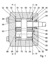
- Fig. 1 shows a gear motor with a housing 10, the one Has interior 12 of two attached to the housing 10 Lids 52, 54 is limited.
- the interior 12 is one Gear arrangement 14 arranged, the two in external engagement intermeshing gears 16, 18.
- the abortion Gear wheel 16 is connected in a rotationally fixed manner to an output shaft 24, over which there is a bearing shell 56, 58 in two Bearing bushes 60, 62 is mounted in the housing 10.
- the output shaft 24 is on an output side 20 through the cover 52 led to the outside and sealed by a shaft seal 22.
- the gear 18 is rotatably connected to an axis 26, over which there is a bearing shell 64, 66 in two bearing bushes 68, 70 is mounted in the housing 10.
- the bearing bushes 60, 68 and the bearing bushes 62, 70 can also be in one piece be executed.
- the gear motor is on a high pressure side 42, 72 in a schematically illustrated inlet 74 with pressure medium acted upon (Fig. 2 and 3).
- the pressure medium is from the High pressure side 42, 72 in tooth gaps of the gear wheels 16, 18 outside along the housing 10 to a low pressure side 34, 44 guided and drives the gears 16, 18.
- On the Low pressure side 34, 44 dip the teeth and tooth gaps into one another and push the pressure medium into a schematic shown sequence 76.
- a radial seal of the gears 16, 18 of the external gear motor takes place depending on the pressure.
- the operating pressure on the High-pressure side 42, 72 acts in the circumferential direction via a forming crescent-shaped gap on the two gears 16, 18 and presses the axis 26 and the shaft 24 of the gears 16, 18 into the bearing bushes 60, 62, 68, 70 radially inwards against the low pressure side 34, 44 with a pressure dependent Operating force.
- a defined one takes place immediately after assembly Entry of the gears 16, 18 in the housing 10 on the Low pressure side 34, 44. On the low pressure side 34, 44 arise Sealing zones with an optimal sealing gap.
- the gears 16, 18 are also axially sealed pressure-dependent, in each case by the outer sides of the on the driven side 20 arranged and the one on the opposite Page 30 arranged bushings 60, 62, 68, 70 with the Operating pressure are applied and the bearing bushes 60, 62, 68, 70 defined contact forces in the axial direction exert the side surfaces of the gears 16, 18.
- the bearing bushes 60, 62, 68, 70 are axially displaceable and have Axial pressure fields 32, 38 on each of their outer sides are limited by axial field seals 28, 36.
- the lids 52, 54 and the housing 10 are each on the outside via a Housing seal 78, 80 sealed. The pressure acts on the Bearing bushes 60, 62, 68, 70 in the precisely limited Axial pressure fields 32, 38 against the inner hydraulic Powers.
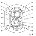
- the axial field seal 28 on the opposite side of the driven side 20 Page 30 limits the axial pressure field 32 on the High pressure side 72 and one open to shaft 24 and axis 26 Field 84 on the low pressure side 34 (Fig. 2). Leak oil from the high pressure side 72 can on the low pressure side 34 in the Sequence 76 are discharged.
- the axial field seal 36 seals on the driven side 20 a shaft seal space 40 in front of the shaft seal 22 to the high pressure side 42 and to the low pressure side 44 (Figs. 1 and 3).
- the shaft seal space is for drainage of oil 40 via a channel 46 with a towards the shaft sealing space 40 closing check valve 48 with that of the first Axial field seal 28 limited to the shaft 24 and the axis 26 open field 84 connected to the low pressure side 34.
- On the shaft seal 22 always acts only the static pressure in the Sequence 76, during pressure peaks in the shaft seal space 40 the axial field seal 36 on the driven side 20 and through the check valve 48 can be avoided, the pressure peaks closes in the outlet 76 and protects the shaft seal 22.
- the leak oil in the shaft seal space 40 is on the the output side 20 opposite side 30 via the channel 46 passed, which essentially consists of a schematic leakage oil line 82 shown in the cover 52 and from a Bore 50 in the axis 26. Holes and channels in the Lids 54 can be avoided.
- Check valve 48 is arranged in the leak oil line 82 in the cover 52.
Landscapes
- Engineering & Computer Science (AREA)
- Mechanical Engineering (AREA)
- General Engineering & Computer Science (AREA)
- Rotary Pumps (AREA)
- Hydraulic Motors (AREA)
- General Details Of Gearings (AREA)
- Gear Transmission (AREA)
Abstract
Description
- Fig. 1
- einen Längsschnitt durch einen Zahnradmotor,
- Fig. 2
- einen Schnitt entlang der Linie II-II und
- Fig. 3
- einen Schnitt entlang der Linie III-III.
Claims (3)
- Zahnradmaschine, insbesondere Zahnradmotor, mit einem Gehäuse (10), das einen Innenraum (12) aufweist, in dem zumindest eine Zahnradanordnung (14) mit wenigstens einem ersten und einem zweiten Zahnrad (16, 18) angeordnet ist, die im Außeneingriff miteinander kämmen, wobei das erste Zahnrad (16) auf einer Welle (24) befestigt ist, die auf einer AnAbtriebsseite (20) nach außen geführt und über eine Wellendichtung (22) abgedichtet ist, und das zweite Zahnrad (18) auf einer Achse (26) angeordnet ist, und mit einer ersten Axialfelddichtung (28), die auf der der An- Abtriebsseite (20) gegenüberliegenden Seite (30) der Zahnräder (16, 18) ein Axialdruckfeld (32) auf einer Hochdruckseite (72) und ein zur Welle (24) und zur Achse (26) offenes Feld (84) auf einer Niederdruckseite (34) begrenzt, und mit einer zweiten Axialfelddichtung (36), die auf der An- Abtriebsseite (20) der Zahnräder (16, 18) ein Axialdruckfeld (38) auf einer Hochdruckseite (42) begrenzt, dadurch gekennzeichnet, daß die zweite Axialfelddichtung (36) einen Wellendichtraum (40) vor der Wellendichtung (22) zur Hochdruckseite (42) und zu einer Niederdruckseite (44) abdichtet, und zur Leckölabführung der Wellendichtraum (40) über einen Kanal (46) mit einem in Richtung Wellendichtraum (40) schließenden Rückschlagventil (48) mit dem von der ersten Axialfelddichtung (28) begrenzten, zur Welle (24) und zur Achse (26) offenen Feld (84) auf der Niederdruckseite (34) verbunden ist.
- Zahnradmaschine nach Anspruch 1, dadurch gekennzeichnet, daß das Lecköl durch einen Kanal (50) in der Achse (26) auf die der An- Abtriebsseite (20) gegenüberliegenden Seite (30) der Zahnräder (16, 18) geleitet ist.
- Zahnradmaschine nach einem der vorhergehenden Ansprüche, dadurch gekennzeichnet, daß das Rückschlagventil (48) in einem Deckel (52) auf der An- Abtriebsseite (20) angeordnet ist.
Applications Claiming Priority (2)
| Application Number | Priority Date | Filing Date | Title |
|---|---|---|---|
| DE19942297A DE19942297A1 (de) | 1999-09-04 | 1999-09-04 | Zahnradmaschine |
| DE19942297 | 1999-09-04 |
Publications (3)
| Publication Number | Publication Date |
|---|---|
| EP1081382A2 true EP1081382A2 (de) | 2001-03-07 |
| EP1081382A3 EP1081382A3 (de) | 2002-08-07 |
| EP1081382B1 EP1081382B1 (de) | 2005-07-20 |
Family
ID=7920844
Family Applications (1)
| Application Number | Title | Priority Date | Filing Date |
|---|---|---|---|
| EP00117962A Expired - Lifetime EP1081382B1 (de) | 1999-09-04 | 2000-08-22 | Zahnradmaschine |
Country Status (2)
| Country | Link |
|---|---|
| EP (1) | EP1081382B1 (de) |
| DE (2) | DE19942297A1 (de) |
Cited By (2)
| Publication number | Priority date | Publication date | Assignee | Title |
|---|---|---|---|---|
| DE102005056909A1 (de) * | 2005-11-29 | 2007-05-31 | Bosch Rexroth Ag | Hydraulische Zahnradmaschine |
| EP2216550A3 (de) * | 2009-02-06 | 2016-07-27 | Illinois Tool Works Inc. | Zahnradpumpe mit Wellendichtung |
Families Citing this family (2)
| Publication number | Priority date | Publication date | Assignee | Title |
|---|---|---|---|---|
| DE102010055682A1 (de) | 2010-12-22 | 2012-06-28 | Robert Bosch Gmbh | Gehäuse einer Außenzahnradmaschine und Außenzahnradmaschine |
| DE102016225883A1 (de) * | 2016-12-21 | 2018-06-21 | Robert Bosch Gmbh | Zahnradpumpe für ein Abwärmerückgewinnungssystem |
Family Cites Families (7)
| Publication number | Priority date | Publication date | Assignee | Title |
|---|---|---|---|---|
| US2487732A (en) * | 1948-02-19 | 1949-11-08 | Borg Warner | Pump-pressure loaded-with unloading relief valve |
| DE1155339B (de) * | 1956-09-06 | 1963-10-03 | Bosch Gmbh Robert | Zahnradfluessigkeitspumpe |
| US3156191A (en) * | 1960-12-23 | 1964-11-10 | Clark Equipment Co | Sealing means for pumps and motors |
| DE2847711A1 (de) * | 1978-11-03 | 1980-05-14 | Bosch Gmbh Robert | Zahnradmaschine (pumpe oder hydromotor) |
| DE2917384A1 (de) * | 1979-04-28 | 1980-10-30 | Zahnradfabrik Friedrichshafen | Hydraulikpumpe, insbesondere fluegelzellenpumpe |
| DE3938135A1 (de) * | 1989-11-16 | 1991-05-23 | Bosch Gmbh Robert | Zahnradpumpe |
| DE4209980A1 (de) * | 1992-03-27 | 1993-09-30 | Bosch Gmbh Robert | Reversierbare Zahnradmaschine |
-
1999
- 1999-09-04 DE DE19942297A patent/DE19942297A1/de not_active Withdrawn
-
2000
- 2000-08-22 EP EP00117962A patent/EP1081382B1/de not_active Expired - Lifetime
- 2000-08-22 DE DE50010738T patent/DE50010738D1/de not_active Expired - Fee Related
Cited By (2)
| Publication number | Priority date | Publication date | Assignee | Title |
|---|---|---|---|---|
| DE102005056909A1 (de) * | 2005-11-29 | 2007-05-31 | Bosch Rexroth Ag | Hydraulische Zahnradmaschine |
| EP2216550A3 (de) * | 2009-02-06 | 2016-07-27 | Illinois Tool Works Inc. | Zahnradpumpe mit Wellendichtung |
Also Published As
| Publication number | Publication date |
|---|---|
| EP1081382B1 (de) | 2005-07-20 |
| DE19942297A1 (de) | 2001-03-08 |
| DE50010738D1 (de) | 2005-08-25 |
| EP1081382A3 (de) | 2002-08-07 |
Similar Documents
| Publication | Publication Date | Title |
|---|---|---|
| EP2921703B1 (de) | Motor-pumpen-einheit | |
| DE102016121241B4 (de) | Hydraulischer Antrieb, hydraulischer Motor und integrierte Pumpe mit dem hydraulischen Antrieb | |
| DE102009012916A1 (de) | Hydraulische Zahnradmaschine | |
| DE19909349A1 (de) | Hydrodynamischer Drehmomentwandler | |
| EP1019637A1 (de) | Radialer schwenkmotor | |
| DE69223919T2 (de) | Stufenlos regelbares Getriebe mit Drehkolbenpumpe | |
| DE60031459T2 (de) | Gerotormotor mit Schmiernuten | |
| DE102005056909A1 (de) | Hydraulische Zahnradmaschine | |
| WO2014001138A2 (de) | Zahnradpumpe | |
| DE102007051349A1 (de) | Hydraulische Zahnradmaschine und Verfahren zur Ansteuerung einer hydraulischen Zahnradmaschine | |
| DE102010055682A1 (de) | Gehäuse einer Außenzahnradmaschine und Außenzahnradmaschine | |
| EP1081382A2 (de) | Zahnradmaschine | |
| DE19924057A1 (de) | Zahnradmaschine (Pumpe oder Motor) | |
| DE102007051352A1 (de) | Hydraulische Zahnradmaschine und Verfahren zur Ansteuerung einer hydraulischen Zahnradmaschine | |
| DE102009037199A1 (de) | Hydraulische Zahnradmaschine | |
| DE102008063500B4 (de) | Hydraulische Maschine | |
| DE102007051350A1 (de) | Hydraulische Zahnradmaschine und Verfahren zur Ansteuerung einer hydraulischen Zahnradmaschine | |
| DE102004047817B3 (de) | Nockenwellenversteller für eine Verbrennungskraftmaschine | |
| DE19528631C2 (de) | Zahnradmaschine | |
| EP1526282A1 (de) | Motorpumpenaggregat | |
| DE102009047626A1 (de) | Zahnradpumpe | |
| DE3004581A1 (de) | Hydrostatische kupplung | |
| DE102021209030A1 (de) | Pumpe mit Pulsationskompensation | |
| DE102012213985A1 (de) | Pumpeneinrichtung | |
| WO2012136398A2 (de) | Innenzahnradpumpe |
Legal Events
| Date | Code | Title | Description |
|---|---|---|---|
| PUAI | Public reference made under article 153(3) epc to a published international application that has entered the european phase |
Free format text: ORIGINAL CODE: 0009012 |
|
| AK | Designated contracting states |
Kind code of ref document: A2 Designated state(s): AT BE CH CY DE DK ES FI FR GB GR IE IT LI LU MC NL PT SE |
|
| AX | Request for extension of the european patent |
Free format text: AL;LT;LV;MK;RO;SI |
|
| PUAL | Search report despatched |
Free format text: ORIGINAL CODE: 0009013 |
|
| AK | Designated contracting states |
Kind code of ref document: A3 Designated state(s): AT BE CH CY DE DK ES FI FR GB GR IE IT LI LU MC NL PT SE |
|
| AX | Request for extension of the european patent |
Free format text: AL;LT;LV;MK;RO;SI |
|
| 17P | Request for examination filed |
Effective date: 20030207 |
|
| AKX | Designation fees paid |
Designated state(s): DE FR GB IT |
|
| 17Q | First examination report despatched |
Effective date: 20040319 |
|
| GRAP | Despatch of communication of intention to grant a patent |
Free format text: ORIGINAL CODE: EPIDOSNIGR1 |
|
| GRAS | Grant fee paid |
Free format text: ORIGINAL CODE: EPIDOSNIGR3 |
|
| GRAA | (expected) grant |
Free format text: ORIGINAL CODE: 0009210 |
|
| AK | Designated contracting states |
Kind code of ref document: B1 Designated state(s): DE FR GB IT |
|
| REG | Reference to a national code |
Ref country code: GB Ref legal event code: FG4D Free format text: NOT ENGLISH |
|
| REF | Corresponds to: |
Ref document number: 50010738 Country of ref document: DE Date of ref document: 20050825 Kind code of ref document: P |
|
| GBT | Gb: translation of ep patent filed (gb section 77(6)(a)/1977) |
Effective date: 20051028 |
|
| ET | Fr: translation filed | ||
| PLBE | No opposition filed within time limit |
Free format text: ORIGINAL CODE: 0009261 |
|
| STAA | Information on the status of an ep patent application or granted ep patent |
Free format text: STATUS: NO OPPOSITION FILED WITHIN TIME LIMIT |
|
| 26N | No opposition filed |
Effective date: 20060421 |
|
| PGFP | Annual fee paid to national office [announced via postgrant information from national office to epo] |
Ref country code: DE Payment date: 20081024 Year of fee payment: 9 |
|
| PGFP | Annual fee paid to national office [announced via postgrant information from national office to epo] |
Ref country code: FR Payment date: 20090819 Year of fee payment: 10 |
|
| PGFP | Annual fee paid to national office [announced via postgrant information from national office to epo] |
Ref country code: GB Payment date: 20090821 Year of fee payment: 10 |
|
| PGFP | Annual fee paid to national office [announced via postgrant information from national office to epo] |
Ref country code: IT Payment date: 20090826 Year of fee payment: 10 |
|
| PG25 | Lapsed in a contracting state [announced via postgrant information from national office to epo] |
Ref country code: DE Free format text: LAPSE BECAUSE OF NON-PAYMENT OF DUE FEES Effective date: 20100302 |
|
| GBPC | Gb: european patent ceased through non-payment of renewal fee |
Effective date: 20100822 |
|
| REG | Reference to a national code |
Ref country code: FR Ref legal event code: ST Effective date: 20110502 |
|
| PG25 | Lapsed in a contracting state [announced via postgrant information from national office to epo] |
Ref country code: IT Free format text: LAPSE BECAUSE OF NON-PAYMENT OF DUE FEES Effective date: 20100822 |
|
| PG25 | Lapsed in a contracting state [announced via postgrant information from national office to epo] |
Ref country code: FR Free format text: LAPSE BECAUSE OF NON-PAYMENT OF DUE FEES Effective date: 20100831 |
|
| PG25 | Lapsed in a contracting state [announced via postgrant information from national office to epo] |
Ref country code: GB Free format text: LAPSE BECAUSE OF NON-PAYMENT OF DUE FEES Effective date: 20100822 |