EP1081394A2 - Blindniet - Google Patents
Blindniet Download PDFInfo
- Publication number
- EP1081394A2 EP1081394A2 EP00119025A EP00119025A EP1081394A2 EP 1081394 A2 EP1081394 A2 EP 1081394A2 EP 00119025 A EP00119025 A EP 00119025A EP 00119025 A EP00119025 A EP 00119025A EP 1081394 A2 EP1081394 A2 EP 1081394A2
- Authority
- EP
- European Patent Office
- Prior art keywords
- grommet
- pin member
- axial
- flange
- temporarily stopping
- Prior art date
- Legal status (The legal status is an assumption and is not a legal conclusion. Google has not performed a legal analysis and makes no representation as to the accuracy of the status listed.)
- Granted
Links
- 230000002787 reinforcement Effects 0.000 description 19
- 238000003780 insertion Methods 0.000 description 10
- 230000037431 insertion Effects 0.000 description 10
- 238000004519 manufacturing process Methods 0.000 description 5
- 238000000034 method Methods 0.000 description 4
- 238000010586 diagram Methods 0.000 description 3
- 230000000694 effects Effects 0.000 description 3
- 238000003825 pressing Methods 0.000 description 2
- 239000000853 adhesive Substances 0.000 description 1
- 230000001070 adhesive effect Effects 0.000 description 1
- 238000012423 maintenance Methods 0.000 description 1
- 229920003002 synthetic resin Polymers 0.000 description 1
- 239000000057 synthetic resin Substances 0.000 description 1
Images


Classifications
-
- F—MECHANICAL ENGINEERING; LIGHTING; HEATING; WEAPONS; BLASTING
- F16—ENGINEERING ELEMENTS AND UNITS; GENERAL MEASURES FOR PRODUCING AND MAINTAINING EFFECTIVE FUNCTIONING OF MACHINES OR INSTALLATIONS; THERMAL INSULATION IN GENERAL
- F16B—DEVICES FOR FASTENING OR SECURING CONSTRUCTIONAL ELEMENTS OR MACHINE PARTS TOGETHER, e.g. NAILS, BOLTS, CIRCLIPS, CLAMPS, CLIPS OR WEDGES; JOINTS OR JOINTING
- F16B19/00—Bolts without screw-thread; Pins, including deformable elements; Rivets
- F16B19/04—Rivets; Spigots or the like fastened by riveting
- F16B19/08—Hollow rivets; Multi-part rivets
- F16B19/10—Hollow rivets; Multi-part rivets fastened by expanding mechanically
- F16B19/1027—Multi-part rivets
- F16B19/1036—Blind rivets
- F16B19/1081—Blind rivets fastened by a drive-pin
-
- F—MECHANICAL ENGINEERING; LIGHTING; HEATING; WEAPONS; BLASTING
- F16—ENGINEERING ELEMENTS AND UNITS; GENERAL MEASURES FOR PRODUCING AND MAINTAINING EFFECTIVE FUNCTIONING OF MACHINES OR INSTALLATIONS; THERMAL INSULATION IN GENERAL
- F16B—DEVICES FOR FASTENING OR SECURING CONSTRUCTIONAL ELEMENTS OR MACHINE PARTS TOGETHER, e.g. NAILS, BOLTS, CIRCLIPS, CLAMPS, CLIPS OR WEDGES; JOINTS OR JOINTING
- F16B21/00—Means for preventing relative axial movement of a pin, spigot, shaft or the like and a member surrounding it; Stud-and-socket releasable fastenings
- F16B21/06—Releasable fastening devices with snap-action
- F16B21/08—Releasable fastening devices with snap-action in which the stud, pin, or spigot has a resilient part
Definitions
- the present invention relates to improvement of a clip used, for example, when a mold ceiling constituting a ceiling part of an automobile is coupled to a ceiling reinforcement and a front head panel, or when plural panels are coupled to one another.
- a ceiling surface constituting the interior of the automobile is so composed that the mold ceiling made of synthetic resin is attached onto the lower surface side (interior side) of the ceiling reinforcement coupled to the front head panel in a state where the ceiling reinforcement is superimposed on the front head panel.
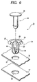
- a clip 21 shown in Fig. 9 has been recently used instead of a bolt member and an adhesive.
- the above clip 21 includes a grommet 24 having an axial leg 23 formed in the shape of a hollow cylinder by a plurality of elastic pieces 22, 22 (three in the figure), and a pin member 26 that expands the above plural elastic pieces 22, 22 by being inserted into a hollow portion formed in the above axial leg 23. Further, flanges 27 and 28 are provided respectively for the above grommet 24 and the pin member 26. In case of the shown structure, a recess portion 29 into which the flange 28 of the above pin member 26 can be fitted is formed on the outer surface (upper surface in Fig. 9) of the flange 27 of the above grommet 24.
- the flange 28 of the above pin member 26 is fitted into the above recess portion 29 so that the above flange 28 does not protrude very much from the flange 27 of the grommet 24.
- the above grommet 24 is inserted into holes 30, 31 provided in positions where the mold ceiling 18, the ceiling reinforcement 17, and the front head panel to be coupled to one another are matched to one another, from one surface side (from interior side, and from upper side in Fig. 9) of the above mold ceiling 18. Then, the above pin member 26 is inserted into the hollow portion 25 of the grommet 24.
- the elastic pieces 22, 22 of the above grommet 21 are expanded on the other surface side (exterior side) of the above ceiling reinforcement 17 (front head panel), and the mold ceiling 18, the ceiling reinforcement 17 and the front head panel can be coupled to one another in a superimposed state on one another.
- the above ceiling reinforcement 17 and the mold ceiling 18 are previously fixed to each other temporarily, and thereafter, they are really fixed to the above front head panel in an automobile assembling factory.
- this assembling method is adopted, the assembling operation is readily performed using the above clip 21. Namely, the above ceiling reinforcement 17 and the mold ceiling 18 are temporarily fixed by the above clip 21.
- the above pin member 26 is not completely inserted into the grommet 24 but is stopped in a half position.
- the elastic pieces 22, 22 of the above grommet 24 are expanded to some degree, and the above ceiling reinforcement 17 and the mold ceiling 18 are a little coupled to each other.
- the ceiling reinforcement 17 and the mold ceiling 18 are carried in the assembling factory in this state, and they are coupled to the above front head panel. At this time, the above pin member 26 is only inserted into the grommet 24 completely, so that the assembling operation is simplified, the manufacturing time is reduced, and the manufacturing cost is reduced.
- JP-B-61-053562 which includes a female member that corresponds to the above grommet and includes a slit, a male member that corresponds to the above pin member, and a temporarily stopping piece that is provided for this male member and fitted in a base end of the above slit.
- the above temporarily stopping piece is fitted in the base end of the slit by inserting the above male member into the female member, whereby the male member and the female member are prevented from separating from each other. Accordingly, such the disadvantages are solved that the pin member 26 drops out on the way of the transportation like the conventional clip 21 shown in Fig. 9 and that the temporarily fixing state cannot be maintained.
- the invention has been made in view of the aforesaid circumstances and therefore an object of the invention is to provide the clip which prevents the pin member from dropping out without the complicated structure and which is satisfactory for the attaching work performance.
- the above pin member in the clip provided with a grommet having an axial leg formed in the shape of a hollow cylinder by a plurality of elastic pieces, and a pin member that expands the above plural elastic pieces by being inserted into a hollow portion formed in the above axial leg, the above pin member includes an axial portion that can be inserted into the above hollow portion, and a temporarily stopping piece that is provided for this axial portion and protrudes outward;
- the above grommet includes a recess portion which is formed on the inner surface of the above axial leg so as to extend from the top portion of the grommet to a slit formed between the adjacent elastic pieces; and the base end portion of the above slit serves as a fitting receiver in which the above temporarily stopping piece is fitted.
- the axial portion of this pin member is inserted into the hollow portion of the grommet. Thereafter, the above temporarily stopping piece is fitted in the fit receiver provided for the grommet. Therefore, the work of inserting the pin member into the grommet is easily performed, and the pin member is effectively prevented from dropping out of the grommet in the temporarily fixing state after the complete insertion.
- the clip according to a second aspect of the invention is characterized in that the above pin member includes a dam formed at a portion with which the above axial leg comes into elastic contact at the real fixing time.
- the elastic piece provided for the grommet is effectively prevented from shifting and moving. Further, such an effect can be also expected that the above pin member is difficult to rotate in relation to the grommet due to the existence of this dam. Therefore, the grommet and the pin are prevented from shifting and moving, and the stable fixing state can be maintained also after the real fixing.
- the clip according to a third aspect of the invention is characterized in that a first flange is formed at the base end of the axial leg of the grommet and a second flange of which the diameter is larger than that of the above first flange is formed at the base end of the axial portion of the pin member and that a surface on the axial portion side of the above second flange is a recess surface into which the above first flange can be fitted.
- the projecting amount of the flange from the wall surface of the panel is reduced and a look is better. Further, the user is prevented from hitching his finger on the projecting flange and being injured, so that safety is improved.
- the clip according to a fourth aspect of the invention is characterized in that a tapered portion is provided for the base end of the hollow portion of the grommet and that the inclination of the leading end portion of the above temporarily stopping piece is steeper than the inclination of the above tapered portion.
- the clip according to a fifth aspect of the invention is characterized in that the above recess portion continues from the middle of the above tapered portion.
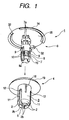
- the clip according to this embodiment includes, as shown in Figs. 1 and 3, a grommet 4 having an axial leg 3 formed in the shape of a hollow cylinder by a plurality of elastic pieces 2 (three elastic pieces in this embodiment), and a pin member 6 that expands the above plural elastic pieces 2 by being inserted into a hollow portion 5 formed in the above axial leg. And, the above grommet 4 is inserted into holes 30, 31 provided in positions where a ceiling reinforcement 17 and a mold ceiling 18 (refer to Figs. 7 and 8) to be coupled to each other are matched to each other, from one surface side (from interior side, and from upper surface side in Fig. 7 and 8) of the above mold ceiling 18.
- the above pin member 6 includes an axial portion 7 capable of being inserted into the above hollow portion 5; a plurality of recess grooves 8 (three grooves in the figures) formed at the leading half portion of this axial portion 7 (at the lower half portion in Figs. 1 and 2A-2C) in the circumferential direction; temporarily stopping pieces 9 that are provided for base end portions (for the upper end portions in Figs. 1 and 2A-2C) of these recess grooves 8 and protrude outward; and earth bank-like dams 10 formed at the leading half portion of the above recess grooves 8 which come into elastic contact with the above axial leg 3.
- each of these dams 10 is formed shallower than that of each of the above recess grooves 8. Further, at the base end portion of the above axial portion 7, thickness cut portions 7a are formed as shown in Figs. 1 and 2A to 2C. Further, in this embodiment, since the three elastic pieces 2 are formed in the above grommet 4, the transverse cross section of the leading end portion of the axial portion 7 is formed substantially triangularly as shown in Fig. 2A to 2C.
- the above recess groove 8 is enlarged and shown in Figs. 4A, 4B and 5A, 5B. It is formed on the rear surface side of the temporarily stopping piece 9 in a state where it is cut in the direction of the base end side of the axial portion 7. That is, on the surface side from the base end of each recess groove 8 to the middle portion thereof, the above temporarily stopping pieces are spaced and provided so as to cover the recess grooves 8. By this constitution, deflection is allowed to the above temporarily stopping pieces 9. Further, the above recess grooves 8 extend to the leading end of the axial portion 7. Accordingly, when this pin member 6 is manufactured, rapping becomes easy, so that time for manufacture and the manufacturing cost can be reduced.
- the inclination ⁇ 2 of a pawl piece 9a formed at the leading end portion of the above temporarily stopping piece 9 is steeper than the inclination ⁇ 1 of a tapered portion 5a at the base end of the hollow portion 5 of the above grommet 4. This fact makes it easy to insert the axial portion 7 into the above hollow portion 5.
- a slit 11 between the adjacent elastic pieces 2 is interposed. And, a base end portion of this slit 11 serves as a fitting receiver 12 in which the above temporarily stopping piece 9 is fitted.
- inner surfaces 2a of the leading end portions of the above elastic pieces 2 are formed so as to be tapered in the direction where they approach each other.
- the aforesaid tapered inner surfaces 2a are, as shown in Fig. 1, formed in the cuspidate shape having the center portions in the width direction of the elastic pieces 2 as an apex (formed substantially in the shape of a triangle in a transverse section).
- the outer surfaces of the leading end portions of the above elastic pieces 2 are also tapered so that the diameter of the axial leg gradually becomes smaller toward the leading end of the axial leg, as shown in Figs. 1 and 3A to 3E. This makes it easy to insert the axial portion 7 into the hole 31 and the like provided for the mold ceiling 18 and the like.
- recess portions 11a are provided on the inner surface of the axial leg 3 of the above grommet 4, which extend from the upper portion of the grommet 4 to the above slits 11.
- the base end of the hollow portion 5 formed in the above grommet 4 is formed as a tapered portion 5a as described above.
- the above recess portion 11a is formed so as to continue to the tapered portion 5a on the way of the tapered portion 5a.
- a first flange 13 is provided for the base end of the axial leg 3 of the above grommet 4, and a second flange 14, of which the diameter is larger than that of the flange 13, is provided for the base end of the axial portion 7 of the above pin member 6.
- a surface on the axial portion 7 side of the above second flange portion 14 is formed as a recess surface 15 into which the above first flange 13 can be fitted.
- the base area of the above recess surface 15 is larger a little than that of the above first flange 13, and the depth of the former 15 is the same as or larger than the height of the latter 13.
- apertures 16 that extend in the longitudinal direction (vertical direction in Fig. 1) are formed in the above elastic pieces 2.
- the temporarily fixing pieces 9 provided for the axial portion 7 of the pin member 6 are guided to the tapered portion 5a of the hollow portion 5, so that the axial portion 7 is in a state where it is readily inserted into the hollow portion 5.
- the above temporarily stopping pieces 9 are deflected by the pressing force from the above hollow portion 5 in a direction where the pieces 9 contract, so that the axial portion 7 is inserted into the hollow portion 5.
- the axial portion 7 is inserted into the hollow portion 5.
- the temporarily stopping pieces 9 are restored, and the pawl pieces 9a are fitted in the fitting receivers 12 of the base ends of the recess portions 11a, so that the axial portion is prevented from moving in the direction opposite to the insertion direction.
- This state is a temporarily fixing state.
- the pawl pieces 9a fit in the base ends of the recess portions 11a to prevent the axial portion from moving in the direction opposite to the insertion direction. Therefore the pin member 6 is effectively prevented from dropping out of the grommet 4.
- the axial portion 7 is further inserted into the inner part of the hollow portion 5 from the above temporarily fixing state.
- this axial portion 7 is inserted.
- the above elastic pieces 2 are restored, and the leading end edges of these elastic pieces 2 are fitted in grooves 8a of which each is formed between the adjacent dams 10 as shown in Figs. 5B and 6.
- the pin member 6 is prevented from coming out in the direction opposite to the insertion direction, that is, it is prevented that the real fixing state is released.
- the pin member 6 Since the axial portion 7 of the above pin member 6 is inserted into the hollow portion 5 of the grommet 4 as described above, the work of inserting the pin member 6 into the grommet 4 is simplified. Further, the pin member 6 is effectively prevented from dropping out of the grommet 4 in either state of the temporarily fixing state and the real fixing state. Namely, in the temporarily fixing state, the temporarily stopping pieces 9 fit in the fitting receivers 12 of the base ends of the slits 11; and in the real fixing state, the leading end edges of the elastic pieces 2 fit in the grooves 8a, 8a. Therefore, the pin member 6 is prevented from moving in the direction where the pin member 6 separates from the grommet 4 (direction of an arrow ⁇ in Fig. 7).
- the elastic pieces 2 provided for grommet 4 is effectively prevented from shifting and rotating due to the existence of the above earth bank-like dams 10, 10. Namely, even in case that these elastic pieces 2 tend to shift, they are obstructed by the above dams 10 and prevented from shifting. It is effective to prevent the grommet 4 from shifting by these dams 10 in a case where some scatter is produced in diameter and shape of each attaching hole formed in the panels (the above ceiling reinforcement 17, the mold ceiling 18, and the like) due to inevitable manufacturing error. Namely, in case that there is the above scatter, the elastic pieces 2 provided for the grommet 4 are readily deflected, so that there is fear that the sufficient and stable fitting power cannot be obtained.
- the surface on the axial portion 7 side of the above second flange portion 14 is formed as the recess surface 15 into which the above first flange 13 can be fitted. Therefore, at the real fixing time, the first flange 13 is fitted in the recess portion 15 on the inner surface of the second flange 14. As a result, the projecting amount of the above second flange 14 from the mold ceiling 18 is reduced and a look becomes better. Further, the user is prevented from hitching his finger on the projecting flange 14 and being injured by contact of a part of his body with the flange 14, so that safety is improved. Further, since the apertures 16 that extend in the longitudinal direction are formed in the above elastic pieces 2 these elastic pieces 2 are easy to deflect. Accordingly, the pin member 6 is readily inserted into the grommet 4.
- recess grooves 32 into which a leading end portion of a minus (-) driver can be inserted are formed in two positions of the outer edge portions of the second flange 14. Accordingly, in case that the really fixed mold ceiling 18 is replaced, when the leading end portion of the minus driver is inserted into these recess grooves 32 and the second flange 14 is operated in a direction where it separates from the first flange 13, the clip can be readily detached from the above mold ceiling 18. Namely, by the operation of the above minus driver, the pin member 6 having the second flange 14 is first extracted from the grommet 4 in some degree (till the temporarily stopping pieces 9 of the above pin member 6 are fitted in the fitting receivers 12 of the grommet 4). Thereafter, while this temporarily fixing state is being maintained, the pin member 6 and the grommet 4 are integrally detached from the mold ceiling 18. Therefore, maintenance of the interior of the automobile can be readily performed.
- the invention is applied to a case where the ceiling reinforcement 17 and the mold ceiling 18 that constitute the ceiling part of the automobile are previously fixed temporarily and then they are coupled to the front head panel of the automobile.
- the clip according to the invention is not limited to the aforesaid example. That is, the invention can be utilized in any cases as long as the clip according to the invention is used in order to couple the plural panels to one another.
- the pin member is readily inserted into the grommet. Further, in the temporarily fixing state after the pin member has been completely inserted, the pin member is effectively prevented from dropping out of the grommet. Accordingly, the temporarily fixing work is readily performed using this clip. And, even in case that the temporarily fixed panels are transported, it is prevented that the pin member drops out during transportation, that the temporarily fixing state cannot be maintained and that fitting of a pair of panels is undone. Further, it is prevented that the trouble caused by dropping-out of the pin member is produced in the assembling process, so that the real fixing work is smoothly performed. Further, in either of the temporarily fixing and the real fixing, the pin member can be inserted into the grommet readily and smoothly, so that the work performance is improved.
- the elastic piece provided for the grommet is effectively prevented from shifting by the existence of the above dam. Further, such an effect can be also expected that the above pin member is difficult to rotate in relation to the grommet due to the existence of this dam. Therefore, the grommet and the pin are prevented from shifting and moving, and the stable fixing state can be maintained also after the real fixing.
- the projecting amount of the flange from the wall surface of the panel is reduced and a look is better. Further, the user is prevented from hitching his finger on the projecting flange and being injured, so that safety is improved.
- the insertion of the axial portion into the above hollow portion is more readily performed, so that the work performance is improved.
- the above temporarily stopping piece is more readily guided to the above recess portion, so that the work performance is improved.
Landscapes
- Engineering & Computer Science (AREA)
- General Engineering & Computer Science (AREA)
- Mechanical Engineering (AREA)
- Insertion Pins And Rivets (AREA)
- Snaps, Bayonet Connections, Set Pins, And Snap Rings (AREA)
- Mechanical Operated Clutches (AREA)
Applications Claiming Priority (2)
| Application Number | Priority Date | Filing Date | Title |
|---|---|---|---|
| JP24877299A JP4105832B2 (ja) | 1999-09-02 | 1999-09-02 | クリップ |
| JP24877299 | 1999-09-02 |
Publications (3)
| Publication Number | Publication Date |
|---|---|
| EP1081394A2 true EP1081394A2 (de) | 2001-03-07 |
| EP1081394A3 EP1081394A3 (de) | 2002-06-05 |
| EP1081394B1 EP1081394B1 (de) | 2006-07-19 |
Family
ID=17183164
Family Applications (1)
| Application Number | Title | Priority Date | Filing Date |
|---|---|---|---|
| EP00119025A Expired - Lifetime EP1081394B1 (de) | 1999-09-02 | 2000-09-01 | Blindniet |
Country Status (5)
| Country | Link |
|---|---|
| US (1) | US6364586B1 (de) |
| EP (1) | EP1081394B1 (de) |
| JP (1) | JP4105832B2 (de) |
| AT (1) | ATE333596T1 (de) |
| DE (1) | DE60029397D1 (de) |
Cited By (7)
| Publication number | Priority date | Publication date | Assignee | Title |
|---|---|---|---|---|
| EP1375931A1 (de) * | 2002-06-12 | 2004-01-02 | Piolax Inc. | Zweiteilige Klammer |
| EP1514706A1 (de) * | 2003-09-03 | 2005-03-16 | Frape Behr S.A. | Rastverbindung von Gehäuseteilen |
| DE102004036621A1 (de) * | 2004-07-28 | 2006-03-23 | A. Raymond & Cie | Spreizniet |
| DE102007016484A1 (de) * | 2007-04-05 | 2008-10-09 | Volkswagen Ag | Lösbarer Spreizclip für eine Clipsverbindung mehrerer Bauteile |
| WO2013097180A1 (zh) * | 2011-12-27 | 2013-07-04 | Yuan Yujun | 一种非预紧力栓连接的防脱套 |
| CN105822157A (zh) * | 2015-01-22 | 2016-08-03 | 株式会社东海理化电机制作所 | 锁芯装置 |
| CN111152704A (zh) * | 2020-01-19 | 2020-05-15 | 宁波均胜科技有限公司 | 一种保持结构及保持结构的安装方法 |
Families Citing this family (49)
| Publication number | Priority date | Publication date | Assignee | Title |
|---|---|---|---|---|
| JP5002095B2 (ja) * | 2001-07-17 | 2012-08-15 | アイリスオーヤマ株式会社 | 木板に支柱を連結するための連結構造 |
| US7105119B2 (en) * | 2002-02-22 | 2006-09-12 | Newfrey Llc | Method of forming integrally molded clip |
| JP4006499B2 (ja) * | 2002-02-22 | 2007-11-14 | ポップリベット・ファスナー株式会社 | 一体成形クリップの成形方法 |
| JP4262470B2 (ja) * | 2002-11-07 | 2009-05-13 | 株式会社ニフコ | 本留め用の雄パーツを有する連結具 |
| JP4091859B2 (ja) * | 2003-03-03 | 2008-05-28 | 株式会社パイオラックス | 締結具 |
| JP2005150159A (ja) * | 2003-11-11 | 2005-06-09 | Toshiba Corp | 半導体装置、及び、半導体装置の製造方法 |
| JP2005188579A (ja) * | 2003-12-25 | 2005-07-14 | Nippon Pop Rivets & Fasteners Ltd | パネル等の固定具 |
| US7736107B2 (en) * | 2004-03-30 | 2010-06-15 | Piolax, Inc. | Clipping device |
| JP4499614B2 (ja) * | 2004-05-31 | 2010-07-07 | 株式会社パイオラックス | クリップ |
| JP4264905B2 (ja) * | 2006-01-23 | 2009-05-20 | 株式会社ホンダアクセス | 部品取付用グロメット |
| WO2007094453A1 (ja) * | 2006-02-17 | 2007-08-23 | Piolax Inc. | 止め具 |
| JP4545711B2 (ja) * | 2006-06-01 | 2010-09-15 | ポップリベット・ファスナー株式会社 | クリップ |
| ES1064799Y (es) * | 2007-01-30 | 2007-08-01 | Carcar Alfredo Jose Alfaro | Protector para el transporte de torres de generadores eolicos |
| JP5243749B2 (ja) * | 2007-08-09 | 2013-07-24 | 株式会社ニフコ | クリップ及び支持部材 |
| JP5145129B2 (ja) * | 2008-06-24 | 2013-02-13 | 株式会社ニフコ | クリップ |
| JP5301388B2 (ja) * | 2009-08-06 | 2013-09-25 | 株式会社パイオラックス | クリップ |
| DE202009016632U1 (de) * | 2009-12-08 | 2011-04-14 | Ramsauer, Dieter | Schnappbefestigung |
| JP5680915B2 (ja) * | 2010-09-14 | 2015-03-04 | 株式会社ニフコ | プッシュリベット |
| WO2012036162A1 (ja) * | 2010-09-17 | 2012-03-22 | 株式会社ニフコ | クリップ |
| US8661614B2 (en) | 2011-08-17 | 2014-03-04 | Symmetry Medical Manufacturing, Inc. | Grommet device with flexible bowed members and methods of using thereof |
| US9277967B2 (en) | 2011-09-14 | 2016-03-08 | Symmetry Medical Manufacturing, Inc. | Universally-sized grommet device and method thereof |
| US8701246B2 (en) | 2011-09-14 | 2014-04-22 | Symmetry Medical Manufacturing, Inc. | Removable grommet device and method of using thereof |
| US8739363B2 (en) | 2011-09-14 | 2014-06-03 | Symmetry Medical Manufacturing, Inc. | Removable grommet device with enlargeable slit and method thereof |
| US9333554B2 (en) * | 2011-11-11 | 2016-05-10 | Illinois Tool Works, Inc | Panel fastening rivet mechanism |
| JP5771126B2 (ja) * | 2011-11-11 | 2015-08-26 | 株式会社ニフコ | クリップ |
| US9771964B2 (en) * | 2012-11-06 | 2017-09-26 | Inter Ikea Systems B.V. | Fastening device, fastening system and furniture assembly |
| DE102014206255A1 (de) | 2014-04-02 | 2015-10-08 | Mahle International Gmbh | Baugruppe mit Clipverbindung |
| JP2015200363A (ja) * | 2014-04-08 | 2015-11-12 | キャタピラー エス エー アール エル | 長尺物保持具 |
| JP6342256B2 (ja) * | 2014-08-04 | 2018-06-13 | 株式会社ニフコ | クリップ |
| US9528540B2 (en) | 2014-08-12 | 2016-12-27 | Newfrey Llc | Insertion-locking pin and grommet and related methods |
| BR112017001804A2 (pt) * | 2014-08-18 | 2017-11-21 | Illinois Tool Works | montagem de fixação de pino e ilhó |
| CN204784050U (zh) * | 2015-06-01 | 2015-11-18 | 吴易璋 | 防震铆钉 |
| US10941800B2 (en) | 2016-03-03 | 2021-03-09 | Carrier Corporation | Fastening system and air handling unit comprising such a fastening system |
| US9873388B2 (en) * | 2016-04-06 | 2018-01-23 | Newfrey Llc | Automotive door trim fastener and molding method |
| US10344792B2 (en) | 2017-01-20 | 2019-07-09 | Ford Global Technologies, Llc | Receiver assembly |
| JP6936131B2 (ja) * | 2017-12-15 | 2021-09-15 | 矢崎総業株式会社 | グロメット |
| US11519446B2 (en) | 2018-11-05 | 2022-12-06 | Illinois Tool Works Inc. | Fastener feedback feature |
| US11608849B2 (en) | 2019-01-04 | 2023-03-21 | Illinois Tool Works Inc. | Grommet removal assemblies and methods |
| USD905546S1 (en) * | 2019-01-04 | 2020-12-22 | Illinois Tool Works Inc. | Fastener |
| US10900513B2 (en) | 2019-04-02 | 2021-01-26 | Newfrey Llc | Re-usable one-push pin and grommet fastener |
| KR102202540B1 (ko) * | 2019-08-14 | 2021-01-13 | 주식회사 니프코코리아 | 자동차의 도어트림 체결용 클립 |
| GB2592442B (en) | 2020-02-28 | 2022-04-20 | Ovvotech Innovations Ltd | Coupling element for an article of furniture |
| US11346385B2 (en) | 2020-04-06 | 2022-05-31 | Illinois Tool Works Inc. | Grommet |
| US20220013257A1 (en) | 2020-07-10 | 2022-01-13 | Illinois Tool Works Inc. | Grommet |
| GB2611069B (en) * | 2021-09-24 | 2024-01-17 | Ovvotech Innovations Ltd | A connector assembly |
| USD991024S1 (en) | 2021-12-15 | 2023-07-04 | Illinois Tool Works Inc. | Fastener |
| USD990300S1 (en) | 2021-12-15 | 2023-06-27 | Illinois Tool Works Inc. | Fastener |
| CN116816189B (zh) * | 2022-03-22 | 2025-08-22 | 广东汇天航空航天科技有限公司 | 锁具、连接组件及其应用 |
| US20240295283A1 (en) * | 2023-03-03 | 2024-09-05 | MasterTek Flow Technologies, LLC | Non-permanent inlet flange and method for custom insert |
Citations (1)
| Publication number | Priority date | Publication date | Assignee | Title |
|---|---|---|---|---|
| JPS6153562B2 (de) | 1978-02-14 | 1986-11-18 | Itw De France |
Family Cites Families (8)
| Publication number | Priority date | Publication date | Assignee | Title |
|---|---|---|---|---|
| US4085651A (en) * | 1977-02-14 | 1978-04-25 | Illinois Tool Works Inc. | Plastic fastener |
| FR2431060A1 (fr) * | 1978-07-13 | 1980-02-08 | Itw De France | Piece de fixation imperdable et reutilisable |
| US4405272A (en) * | 1981-03-11 | 1983-09-20 | Phillips Plastics Corporation | Two-piece fastener with front shoulder |
| US4488843A (en) * | 1982-07-16 | 1984-12-18 | Illinois Tool Works Inc. | Reusable one piece drive fastener |
| JPS6153562A (ja) | 1984-08-24 | 1986-03-17 | Hitachi Ltd | 超音波探触子 |
| JPH084720A (ja) * | 1994-06-20 | 1996-01-09 | Nifco Inc | クリップ |
| DE29622477U1 (de) * | 1995-12-29 | 1997-02-20 | Emhart Inc., Newark, Del. | Wasserdichtes zweistufiges Niet |
| JP3749017B2 (ja) * | 1998-04-03 | 2006-02-22 | 株式会社パイオラックス | 固定クリップ |
-
1999
- 1999-09-02 JP JP24877299A patent/JP4105832B2/ja not_active Expired - Fee Related
-
2000
- 2000-08-31 US US09/652,663 patent/US6364586B1/en not_active Expired - Lifetime
- 2000-09-01 DE DE60029397T patent/DE60029397D1/de not_active Expired - Lifetime
- 2000-09-01 AT AT00119025T patent/ATE333596T1/de not_active IP Right Cessation
- 2000-09-01 EP EP00119025A patent/EP1081394B1/de not_active Expired - Lifetime
Patent Citations (1)
| Publication number | Priority date | Publication date | Assignee | Title |
|---|---|---|---|---|
| JPS6153562B2 (de) | 1978-02-14 | 1986-11-18 | Itw De France |
Cited By (10)
| Publication number | Priority date | Publication date | Assignee | Title |
|---|---|---|---|---|
| EP1375931A1 (de) * | 2002-06-12 | 2004-01-02 | Piolax Inc. | Zweiteilige Klammer |
| US6769849B2 (en) | 2002-06-12 | 2004-08-03 | Piolax Inc. | Two-piece clip |
| EP1514706A1 (de) * | 2003-09-03 | 2005-03-16 | Frape Behr S.A. | Rastverbindung von Gehäuseteilen |
| DE102004036621A1 (de) * | 2004-07-28 | 2006-03-23 | A. Raymond & Cie | Spreizniet |
| DE102004036621B4 (de) * | 2004-07-28 | 2007-04-26 | A. Raymond Et Cie | Spreizniet |
| DE102007016484A1 (de) * | 2007-04-05 | 2008-10-09 | Volkswagen Ag | Lösbarer Spreizclip für eine Clipsverbindung mehrerer Bauteile |
| DE102007016484B4 (de) | 2007-04-05 | 2018-03-15 | Volkswagen Ag | Lösbarer Spreizclip für eine Clipsverbindung mehrerer Bauteile |
| WO2013097180A1 (zh) * | 2011-12-27 | 2013-07-04 | Yuan Yujun | 一种非预紧力栓连接的防脱套 |
| CN105822157A (zh) * | 2015-01-22 | 2016-08-03 | 株式会社东海理化电机制作所 | 锁芯装置 |
| CN111152704A (zh) * | 2020-01-19 | 2020-05-15 | 宁波均胜科技有限公司 | 一种保持结构及保持结构的安装方法 |
Also Published As
| Publication number | Publication date |
|---|---|
| US6364586B1 (en) | 2002-04-02 |
| ATE333596T1 (de) | 2006-08-15 |
| DE60029397D1 (de) | 2006-08-31 |
| EP1081394B1 (de) | 2006-07-19 |
| JP2001074015A (ja) | 2001-03-23 |
| EP1081394A3 (de) | 2002-06-05 |
| JP4105832B2 (ja) | 2008-06-25 |
Similar Documents
| Publication | Publication Date | Title |
|---|---|---|
| EP1081394B1 (de) | Blindniet | |
| EP1186788B1 (de) | Clip | |
| US6474616B2 (en) | Article holding device | |
| US7207759B2 (en) | Fastener for panels or the like | |
| US5704658A (en) | Connector having improved removability | |
| US8037582B2 (en) | Fastener | |
| US7360964B2 (en) | Joint structure | |
| US8496420B2 (en) | Clip | |
| US6932416B2 (en) | Vehicular door trim having a molded-in substrate fastener | |
| US7862273B2 (en) | Part mounting mechanism | |
| JP4485281B2 (ja) | 留め具 | |
| EP1862678A2 (de) | Clip mit Stift und Hülse | |
| JP2007315517A (ja) | 2ピースクリップ | |
| JP3219310B2 (ja) | 止め具 | |
| JP4538964B2 (ja) | エアバッグモジュールの取付構造 | |
| US5575175A (en) | Shift lever assembly | |
| JP2006046536A (ja) | 留め具 | |
| JPH11314552A (ja) | 車両用グリルの取付構造 | |
| GB2305961A (en) | A releasable clip or rivet having a segmented leg expandable by an insertion pin | |
| KR960032170A (ko) | 부재들을 고정시키는 방법 및 파스너 | |
| JPH0748417Y2 (ja) | インストルメントパネルの構造 | |
| JP2006044513A (ja) | ノブの装着構造及び装着方法 | |
| JPH08119120A (ja) | ステアリングコラムカバー | |
| JP2591405Y2 (ja) | 止め具 | |
| JPH0771430A (ja) | 止め輪 |
Legal Events
| Date | Code | Title | Description |
|---|---|---|---|
| PUAI | Public reference made under article 153(3) epc to a published international application that has entered the european phase |
Free format text: ORIGINAL CODE: 0009012 |
|
| AK | Designated contracting states |
Kind code of ref document: A2 Designated state(s): AT BE CH CY DE DK ES FI FR GB GR IE IT LI LU MC NL PT SE |
|
| AX | Request for extension of the european patent |
Free format text: AL;LT;LV;MK;RO;SI |
|
| PUAL | Search report despatched |
Free format text: ORIGINAL CODE: 0009013 |
|
| AK | Designated contracting states |
Kind code of ref document: A3 Designated state(s): AT BE CH CY DE DK ES FI FR GB GR IE IT LI LU MC NL PT SE |
|
| AX | Request for extension of the european patent |
Free format text: AL;LT;LV;MK;RO;SI |
|
| RIC1 | Information provided on ipc code assigned before grant |
Free format text: 7F 16B 19/10 A, 7F 16B 21/08 B, 7F 16B 5/06 B |
|
| 17P | Request for examination filed |
Effective date: 20021008 |
|
| AKX | Designation fees paid |
Designated state(s): AT BE CH CY DE DK ES FI FR GB GR IE IT LI LU MC NL PT SE |
|
| GRAP | Despatch of communication of intention to grant a patent |
Free format text: ORIGINAL CODE: EPIDOSNIGR1 |
|
| GRAC | Information related to communication of intention to grant a patent modified |
Free format text: ORIGINAL CODE: EPIDOSCIGR1 |
|
| GRAS | Grant fee paid |
Free format text: ORIGINAL CODE: EPIDOSNIGR3 |
|
| GRAA | (expected) grant |
Free format text: ORIGINAL CODE: 0009210 |
|
| AK | Designated contracting states |
Kind code of ref document: B1 Designated state(s): AT BE CH CY DE DK ES FI FR GB GR IE IT LI LU MC NL PT SE |
|
| PG25 | Lapsed in a contracting state [announced via postgrant information from national office to epo] |
Ref country code: IT Free format text: LAPSE BECAUSE OF FAILURE TO SUBMIT A TRANSLATION OF THE DESCRIPTION OR TO PAY THE FEE WITHIN THE PRESCRIBED TIME-LIMIT;WARNING: LAPSES OF ITALIAN PATENTS WITH EFFECTIVE DATE BEFORE 2007 MAY HAVE OCCURRED AT ANY TIME BEFORE 2007. THE CORRECT EFFECTIVE DATE MAY BE DIFFERENT FROM THE ONE RECORDED. Effective date: 20060719 Ref country code: LI Free format text: LAPSE BECAUSE OF FAILURE TO SUBMIT A TRANSLATION OF THE DESCRIPTION OR TO PAY THE FEE WITHIN THE PRESCRIBED TIME-LIMIT Effective date: 20060719 Ref country code: NL Free format text: LAPSE BECAUSE OF FAILURE TO SUBMIT A TRANSLATION OF THE DESCRIPTION OR TO PAY THE FEE WITHIN THE PRESCRIBED TIME-LIMIT Effective date: 20060719 Ref country code: FI Free format text: LAPSE BECAUSE OF FAILURE TO SUBMIT A TRANSLATION OF THE DESCRIPTION OR TO PAY THE FEE WITHIN THE PRESCRIBED TIME-LIMIT Effective date: 20060719 Ref country code: AT Free format text: LAPSE BECAUSE OF FAILURE TO SUBMIT A TRANSLATION OF THE DESCRIPTION OR TO PAY THE FEE WITHIN THE PRESCRIBED TIME-LIMIT Effective date: 20060719 Ref country code: BE Free format text: LAPSE BECAUSE OF FAILURE TO SUBMIT A TRANSLATION OF THE DESCRIPTION OR TO PAY THE FEE WITHIN THE PRESCRIBED TIME-LIMIT Effective date: 20060719 Ref country code: CH Free format text: LAPSE BECAUSE OF FAILURE TO SUBMIT A TRANSLATION OF THE DESCRIPTION OR TO PAY THE FEE WITHIN THE PRESCRIBED TIME-LIMIT Effective date: 20060719 |
|
| REG | Reference to a national code |
Ref country code: GB Ref legal event code: FG4D |
|
| REG | Reference to a national code |
Ref country code: CH Ref legal event code: EP |
|
| REG | Reference to a national code |
Ref country code: IE Ref legal event code: FG4D |
|
| REF | Corresponds to: |
Ref document number: 60029397 Country of ref document: DE Date of ref document: 20060831 Kind code of ref document: P |
|
| PG25 | Lapsed in a contracting state [announced via postgrant information from national office to epo] |
Ref country code: IE Free format text: LAPSE BECAUSE OF NON-PAYMENT OF DUE FEES Effective date: 20060901 |
|
| PG25 | Lapsed in a contracting state [announced via postgrant information from national office to epo] |
Ref country code: MC Free format text: LAPSE BECAUSE OF NON-PAYMENT OF DUE FEES Effective date: 20060930 |
|
| PG25 | Lapsed in a contracting state [announced via postgrant information from national office to epo] |
Ref country code: SE Free format text: LAPSE BECAUSE OF FAILURE TO SUBMIT A TRANSLATION OF THE DESCRIPTION OR TO PAY THE FEE WITHIN THE PRESCRIBED TIME-LIMIT Effective date: 20061019 Ref country code: DK Free format text: LAPSE BECAUSE OF FAILURE TO SUBMIT A TRANSLATION OF THE DESCRIPTION OR TO PAY THE FEE WITHIN THE PRESCRIBED TIME-LIMIT Effective date: 20061019 |
|
| PG25 | Lapsed in a contracting state [announced via postgrant information from national office to epo] |
Ref country code: DE Free format text: LAPSE BECAUSE OF FAILURE TO SUBMIT A TRANSLATION OF THE DESCRIPTION OR TO PAY THE FEE WITHIN THE PRESCRIBED TIME-LIMIT Effective date: 20061020 |
|
| PG25 | Lapsed in a contracting state [announced via postgrant information from national office to epo] |
Ref country code: ES Free format text: LAPSE BECAUSE OF FAILURE TO SUBMIT A TRANSLATION OF THE DESCRIPTION OR TO PAY THE FEE WITHIN THE PRESCRIBED TIME-LIMIT Effective date: 20061030 |
|
| PG25 | Lapsed in a contracting state [announced via postgrant information from national office to epo] |
Ref country code: PT Free format text: LAPSE BECAUSE OF FAILURE TO SUBMIT A TRANSLATION OF THE DESCRIPTION OR TO PAY THE FEE WITHIN THE PRESCRIBED TIME-LIMIT Effective date: 20061219 |
|
| NLV1 | Nl: lapsed or annulled due to failure to fulfill the requirements of art. 29p and 29m of the patents act | ||
| EN | Fr: translation not filed | ||
| PLBE | No opposition filed within time limit |
Free format text: ORIGINAL CODE: 0009261 |
|
| STAA | Information on the status of an ep patent application or granted ep patent |
Free format text: STATUS: NO OPPOSITION FILED WITHIN TIME LIMIT |
|
| 26N | No opposition filed |
Effective date: 20070420 |
|
| PG25 | Lapsed in a contracting state [announced via postgrant information from national office to epo] |
Ref country code: FR Free format text: LAPSE BECAUSE OF FAILURE TO SUBMIT A TRANSLATION OF THE DESCRIPTION OR TO PAY THE FEE WITHIN THE PRESCRIBED TIME-LIMIT Effective date: 20070511 |
|
| PG25 | Lapsed in a contracting state [announced via postgrant information from national office to epo] |
Ref country code: LU Free format text: LAPSE BECAUSE OF NON-PAYMENT OF DUE FEES Effective date: 20060901 |
|
| PG25 | Lapsed in a contracting state [announced via postgrant information from national office to epo] |
Ref country code: CY Free format text: LAPSE BECAUSE OF FAILURE TO SUBMIT A TRANSLATION OF THE DESCRIPTION OR TO PAY THE FEE WITHIN THE PRESCRIBED TIME-LIMIT Effective date: 20060719 Ref country code: FR Free format text: LAPSE BECAUSE OF FAILURE TO SUBMIT A TRANSLATION OF THE DESCRIPTION OR TO PAY THE FEE WITHIN THE PRESCRIBED TIME-LIMIT Effective date: 20060719 |
|
| PGFP | Annual fee paid to national office [announced via postgrant information from national office to epo] |
Ref country code: GR Payment date: 20060930 Year of fee payment: 7 |
|
| PG25 | Lapsed in a contracting state [announced via postgrant information from national office to epo] |
Ref country code: GR Free format text: LAPSE BECAUSE OF NON-PAYMENT OF DUE FEES Effective date: 20070930 |
|
| PGFP | Annual fee paid to national office [announced via postgrant information from national office to epo] |
Ref country code: GB Payment date: 20130828 Year of fee payment: 14 |
|
| GBPC | Gb: european patent ceased through non-payment of renewal fee |
Effective date: 20140901 |
|
| PG25 | Lapsed in a contracting state [announced via postgrant information from national office to epo] |
Ref country code: GB Free format text: LAPSE BECAUSE OF NON-PAYMENT OF DUE FEES Effective date: 20140901 |