EP1081488A2 - Four electrothermique pour spectroscopie d'absorption atomique - Google Patents
Four electrothermique pour spectroscopie d'absorption atomique Download PDFInfo
- Publication number
- EP1081488A2 EP1081488A2 EP00119021A EP00119021A EP1081488A2 EP 1081488 A2 EP1081488 A2 EP 1081488A2 EP 00119021 A EP00119021 A EP 00119021A EP 00119021 A EP00119021 A EP 00119021A EP 1081488 A2 EP1081488 A2 EP 1081488A2
- Authority
- EP
- European Patent Office
- Prior art keywords
- furnace
- sample
- furnace part
- electrodes
- brackets
- Prior art date
- Legal status (The legal status is an assumption and is not a legal conclusion. Google has not performed a legal analysis and makes no representation as to the accuracy of the status listed.)
- Withdrawn
Links
Images


Classifications
-
- G—PHYSICS
- G01—MEASURING; TESTING
- G01N—INVESTIGATING OR ANALYSING MATERIALS BY DETERMINING THEIR CHEMICAL OR PHYSICAL PROPERTIES
- G01N21/00—Investigating or analysing materials by the use of optical means, i.e. using sub-millimetre waves, infrared, visible or ultraviolet light
- G01N21/62—Systems in which the material investigated is excited whereby it emits light or causes a change in wavelength of the incident light
- G01N21/71—Systems in which the material investigated is excited whereby it emits light or causes a change in wavelength of the incident light thermally excited
- G01N21/74—Systems in which the material investigated is excited whereby it emits light or causes a change in wavelength of the incident light thermally excited using flameless atomising, e.g. graphite furnaces
Definitions
- the invention relates to an electrothermal furnace for an atomic absorption spectrometer for converting a sample to be examined into the atomized state with a a first pair of electrodes connected first hollow body-shaped furnace part with a first opening for introducing the sample and one connected to a second pair of electrodes second hollow body-shaped furnace part with a second opening for insertion the sample.
- a corresponding two-part furnace also known as a "two-step furnace” consists of a graphite tube, which is placed directly over a graphite container takes the sample, is arranged. In the tube surface opposite the container an opening is provided which is aligned with the position of the container and with whose diameter matches, but with the graphite tube and the container from each other are spaced.
- the graphite tube and the container can be heated separately, whereby Usually first the graphite tube to the desired high screen temperature is brought and then the container containing the sample is heated.
- the various components of the sample get after evaporation due to thermal Movement of the atoms through the opening in the graphite tube.
- the positions of the graphite tube and the Container mechanically fixed.
- the relative location of the two Furnace parts fixed to each other.
- the sample is made using a suitable one automatic device via an accessible top of the graphite tube dosing opening supplied to the container.
- this metering opening reduces the sensitivity of the spectrometer due to sample atoms diffusing out.
- the automatic sample introduction device is difficult to align.
- the execution of the spectroscopic analysis with increased or reduced ambient pressure with only one manual sample introduction using a chunky and complex vacuum or Pump device possible.
- the object of the present invention is to provide the known electrothermal furnace to improve the aforementioned restrictions.
- This task is thereby for an electrothermal furnace of the type mentioned solved that the first furnace part and the second furnace part each attached to a bracket which are movable between a first and a second position, that the first part of the furnace can be loaded with the sample in the first position and that in the second position, the openings of the first and second furnace parts are aligned with one another in this way are that the sample can be transferred from the first furnace part to the second furnace part, in the second position a necessary for electrical and thermal decoupling Distance between the first furnace part and the second furnace part is set reproducibly is.
- the structure of the electrothermal furnace according to the invention enables the first Oven part can be loaded with a sample if the brackets, each the first and pick up the second part of the furnace, are in the second position. So that's an additional one Dosing opening with the associated disadvantages, as in the prior art Technology the case is unnecessary. Furthermore, the second position of the brackets ensures that the mechanical fixation of the furnace parts is reproducible. It is therefore reproducible Analysis conditions both with regard to the light beam penetrating the second furnace part as well as the thermal transport of the atomized sample components given.
- Another advantage of the electrothermal furnace according to the invention is in that by the precise and reproducible definition of the bracket in the second position a distance necessary for electrical and thermal decoupling between the first and the second furnace part can be minimized, whereby the Sensitivity of the spectrometer is improved compared to the prior art.
- brackets are each rotatable or pivotable relative to one another linearly or in any combination thereof only guided in one way educated.
- brackets can be made using easily manufactured elements, such as, for example Swivel joints or rails are movable relative to each other.
- one of the holders is provided with a Auxiliary element for automatic transfer of the first and second furnace parts each in the first and second positions connected.
- the drive element advantageously comprises a pneumatic or an electrical one Secondary unit. Atomization can thus be carried out in a simple and cost-effective manner by means of a simple control device which is operator and program controlled can be realized.
- the first furnace part is in a first depression one of the brackets and the second furnace part in a second recess in the other Bracket arranged, the first and the second recess in the second position form a combined cavity that is gas-tight to the environment.
- This arrangement has the advantage that the first and second furnace parts have a reduced or an increased pressure can be applied, and thus the analysis the sample can be carried out under the desired pressure conditions without a bulky and complex vacuum or pumping device is necessary.
- the brackets include a spacer around the second position to define mechanically. In this way, the necessary distance between the first and second furnace parts and the orientation of the first and second openings simple design.
- the spacer element comprises the first depression delimiting, raised ring with a seal on one of the brackets and a recess on the other corresponding to the raised ring with the seal Bracket.
- the spacer element comprises a guide pin one of the brackets and a guide bush that fits the guide pin on the other bracket.
- either the first or the second depression comprises at least one Fluid access opening.
- the sample to be analyzed can be Apply negative pressure, and it is still possible to use additional gases, such as Argon to be introduced into the first and / or second part of the furnace.
- the first pair of electrodes with one of the holders and the second pair of electrodes is connected to the other holder in a gastight manner.
- the holders advantageously comprise a cooling element.
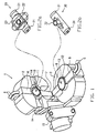
- Figure 1 shows a perspective of a three-dimensional view of the preferred embodiment the invention.
- Reference number 1 designates the electrothermal according to the invention Furnace in a first position, which allows furnace 1 to be loaded with a sample.
- brackets 2 and 3 are shown tilted at an angle to each other.
- the holder 2 has the electrode blocks 6 and 7, with the electrode 6 the cooling water connections 4 are provided.
- the holder 3 has the electrode blocks 8 and 9, wherein 8 cooling water connections 5 are provided on the electrode are.
- the brackets 2 and 3 as well as the electrode blocks 6, 7 and 8, 9 consist of the same material, such as brass, manufactured. But there can also be different material components for the holder and the electrodes are used. Electrically and thermally well conductive materials preference is to be given.
- the bracket 3 In the middle of the holder 2 there is a cylindrical one Well 10, which is radially delimited by an edge 11.
- the bracket 3 in the middle of a cylindrical cavity 12 which is radial from an edge 13 is limited, which is provided on its upper edge with a seal.
- the electrodes 6 and 7 and the edge 11 compared to that in Figure 1 after front facing surface of the bracket 2 offset to the rear.
- the electrodes 8 and 9 and edge 13, on the other hand, are to the surface of FIG Bracket 3 protruding upwards.
- the bracket 2 is through the recess 10 and itself tubes 14 located opposite each other divided into two areas.
- the tubes 14 are connected to the recess 10 and to the outside with quartz windows and suitable heat-resistant O-rings sealed.
- the tubes 14 form together with the Indentation 10 the optical axis for the light beam analyzing the sample.
- the brackets 2 and 3 are connected to a rotary drive unit 15, whose axis of rotation in this Embodiment is parallel to the optical axi
- the holder 2 When the rotary drive unit 15 is activated, the holder 2 is replaced by that shown in FIG first position into a second position so that the opposite one another Surfaces of the brackets 2 and 3 are parallel and spaced and thus form the second position of the electrothermal furnace.
- the exact position of the brackets 2 and 3 to each other is the integrated in the edge 13 seal that an electrically insulating material is guaranteed.
- Figure 2a shows a perspective view of a second furnace part 20, which is in the recess 10 is attached in the holder 2.
- the second furnace part 20, which is made of graphite, has electrode terminals 21 that allow a sample detection tube 22 through which the light beam runs in the axial direction during the analysis to be heated in the transverse direction. Furthermore, the second furnace part 20 has a second opening 23 which is connected to the sample detection tube 22 communicates.
- Figure 2b shows a perspective view of a first furnace part 30, which is in the cylindrical Cavity 12 of the bracket 3 is mounted.
- the furnace part made of graphite has electrode connections 31 at both ends.
- On the outer wall of the first Furnace part 30 has a crucible 32 forming a cylindrical interior.
- the Crucible 32 is preferably designed such that there is a current flow through the crucible 32 results in an even temperature distribution.
- the crucible 32 can be easily loaded with a solid or liquid sample
- the brackets 2 and 3 are parallel to each other, the second furnace part 20 and the first furnace part 30 are so close to each other aligned that the opening of the crucible 32 is aligned with the second opening 23.
- Figure 3 shows schematically a cross section through the embodiment shown in Figure 1 along the electrodes 8, 9 and 6, 7 when the furnace 1 is in the second position.
- the figure shows the arrangement without the first and second furnace parts 30, 20.
- identical parts to Figure 1 are given the same reference numerals.
- the Electrodes 6, 7 and 8, 9 each in the radially inward direction with respect to the Brackets 2 and 3 graphite connectors 16.
- the electrodes 6 and 8 have the cooling water connections 4 and 5 with spring-loaded adjusting screws 17.
- the adjusting screws 17 act on the movable electrodes 6 and 7 with a mechanical one Bias and allow electrodes 6 and 7 to retreat, provided that these are subjected to a compressive force that exceeds the pretension.
- the recess 10 together with the cylindrical cavity 12 form the Edge 13 and the boundary 11 a volume, which by a seal 19 against the Environment is sealed gas-tight.
- the seal 19, which acts as a heat-resistant O-ring is made of electrically insulating material, at the same time prevents direct mechanical contact between the edge 11 and the edge 13.
- the electrodes 6, 7 and 8, 9 each to that of the depression 10 and the cylindrical cavity 12 formed volume sealed with suitable seals (not shown in Figure 3) gas-tight. It also allows a connector 18, the volume through the recess 10 and the cylindrical cavity 12 is formed with negative or positive pressure act upon. If necessary, further nozzles can be provided, for example allow the supply of a gas. Alternatively, a gas supply can also be carried out the electrodes are done.
- the axis of rotation of the rotary actuator 15, which is not shown in FIG. 3 is identified by the marking in the electrode 7.
- Figure 4 shows schematically the arrangement described with reference to Figure 3, however the first furnace part 30 each with the electrode connections 31 between the electrodes 9 and 8 by means of the electrode connections 16 and the second furnace part 20 to the Electrode connections 21 by means of the electrode connections 16 between the electrodes 6, 7 are supported.
- the opening of the crucible 32 is aligned with the second opening 23 of the second furnace part 20. Due to the movable electrodes 6 and 7, the thermal Expansion of the first and second furnace parts can be compensated.
- the furnace When operating the furnace 1, the furnace is first turned by rotating the holder 2 Rotation axis of the drive unit 15 rotated until the first position shown in Figure 1 is reached is. In this position, the crucible 32 of the first furnace part 30 can be automatically or manually can be easily loaded with a sample. Dosing the sample in the invention The furnace can be carried out in a simple manner, since a crucible 32 can be used large opening is ready. This is particularly advantageous for solid samples. Subsequently is carried out according to an exemplary conventional two-step mode of operation Control of the drive unit 15, which can be done by pressing a button or program-controlled can, the furnace 1 rotated into the second position shown in Figures 3 and 4. A voltage is then advantageously first applied to the electrodes 6 and 7 created.
- the invention allows the following preferred Mode of operation. Immediately after loading the crucible 32 with a sample in In the first position, a voltage is applied to electrodes 8 and 9 around the sample to dry when the oven 1 is open. Leaving components of the Samples that are undesirable during the analysis process therefore do not get into the second Furnace part. After the furnace 1 has been moved into the second position, the second furnace part can be opened the desired operating temperature can be heated and by suitable heating of the In the first part of the furnace, the sample is transferred accordingly.
- the Neck 18, the sample with negative or positive pressure is also possible via the connector 18 or additional connectors, which are not shown in the figures, or by the electrodes, the crucible 32 and / or the sample detection tube 22 with one to apply additional gas. It is particularly advantageous when cleaning the oven, i.e. when heating the oven without a sample, apply a vacuum to Support evaporation of previous sample residues. In contrast, conventional Inadequate cleaning stoves a common cause of "memory" effects thus severely restrict the applicability of the furnace technology.
- the furnace according to the invention can be used particularly advantageously in atomic absorption spectroscopy using continuous radiation. Because the sensitivity of the spectrometer proportional to the gas pressure due to the reduced diffusion out of the Sample atoms rising from the furnace, the dynamic range can be analyzed with a continuous source by pressurization in the furnace according to the invention clearly compared to conventional furnaces that do not operate with different gas pressures allow, expand.
- the present invention has been described with reference to a preferred embodiment, in which the brackets 2 and 3 are made of brass. However, it is possible to do any Material that has the required electrical and thermal properties, such as such as copper, silver, gold etc. or corresponding compounds. As electrode connections the electrodes 6, 7 and 8, 9 and the electrode connections 21 of the second furnace part and the electrode connections 31 of the first furnace part became graphite used. However, it is conceivable to use other heat-resistant and current-conducting materials use. Furthermore, in the described embodiment, a pneumatic rotary drive, which provides high reproducible mechanical accuracy. It However, it is possible to use other drives with appropriate accuracy, such as to use electric rotary motors, stepper motors, linear motors etc.
- the movement, which moves the furnace 1 from the first position to the second position need not necessarily be a rotary motion.
- drive means can be provided be a linear relative movement between the brackets 2 and 3rd cause, for example lifting or moving the brackets 2 and 3.
- Furthermore can adjust the mechanical alignment of the second opening 23 and the crucible 32 spacers other than those described in this embodiment, such as a guide pin with associated guide bushing, partially made of electrically insulating Material exist, be effected.
- the exact distance can be observed between the first and second furnace parts as well as the orientation of the second Opening with the crucible through the drive element alone or in combination with spacer elements can be ensured without leadership.
- the shape of the first and second furnace part is not on the shapes shown in Figures 2 and 4 limited, but can be modified appropriately.
Landscapes
- Health & Medical Sciences (AREA)
- Life Sciences & Earth Sciences (AREA)
- Analytical Chemistry (AREA)
- Biochemistry (AREA)
- General Life Sciences & Earth Sciences (AREA)
- Nuclear Medicine, Radiotherapy & Molecular Imaging (AREA)
- Physics & Mathematics (AREA)
- Chemical & Material Sciences (AREA)
- Environmental & Geological Engineering (AREA)
- Geology (AREA)
- General Health & Medical Sciences (AREA)
- General Physics & Mathematics (AREA)
- Immunology (AREA)
- Pathology (AREA)
- Sampling And Sample Adjustment (AREA)
- Investigating Or Analysing Materials By Optical Means (AREA)
Applications Claiming Priority (2)
| Application Number | Priority Date | Filing Date | Title |
|---|---|---|---|
| DE19941874A DE19941874C2 (de) | 1999-09-02 | 1999-09-02 | Elektrothermischer Ofen für ein Atomabsorptionsspektrometer |
| DE19941874 | 1999-09-02 |
Publications (2)
| Publication Number | Publication Date |
|---|---|
| EP1081488A2 true EP1081488A2 (fr) | 2001-03-07 |
| EP1081488A3 EP1081488A3 (fr) | 2001-10-24 |
Family
ID=7920579
Family Applications (1)
| Application Number | Title | Priority Date | Filing Date |
|---|---|---|---|
| EP00119021A Withdrawn EP1081488A3 (fr) | 1999-09-02 | 2000-09-01 | Four electrothermique pour spectroscopie d'absorption atomique |
Country Status (3)
| Country | Link |
|---|---|
| US (1) | US6552786B1 (fr) |
| EP (1) | EP1081488A3 (fr) |
| DE (1) | DE19941874C2 (fr) |
Families Citing this family (5)
| Publication number | Priority date | Publication date | Assignee | Title |
|---|---|---|---|---|
| DE10128272A1 (de) * | 2001-06-12 | 2002-12-19 | Perkin Elmer Bodenseewerk Zwei | Ofen |
| JP4038123B2 (ja) * | 2002-05-29 | 2008-01-23 | 株式会社堀場製作所 | 含有酸素分析装置および含有酸素分析方法 |
| WO2010109989A1 (fr) | 2009-03-27 | 2010-09-30 | 三菱電機株式会社 | Dispositif d'atomisation électrostatique, appareils, climatiseur, et réfrigérateur |
| DE102017119631A1 (de) * | 2017-08-28 | 2019-02-28 | Analytik Jena Ag | Anordnung zur elektrothermischen Atomisierung und Atom-Absorptions-Spektrometer |
| WO2022024505A1 (fr) * | 2020-07-29 | 2022-02-03 | 株式会社島津製作所 | Spectrophotomètre à absorption atomique |
Family Cites Families (5)
| Publication number | Priority date | Publication date | Assignee | Title |
|---|---|---|---|---|
| DE2617928C3 (de) | 1976-04-23 | 1978-10-26 | Bodenseewerk Perkin-Elmer & Co Gmbh, 7770 Ueberlingen | Graphitrohrküvette für die flammenlose Atomabsorptions-Spektroskopie |
| DE2710864C3 (de) * | 1977-03-12 | 1979-11-29 | Bodenseewerk Perkin-Elmer & Co Gmbh, 7770 Ueberlingen | Graphitrohrküvette für die flammenlose Atomabsorptionsspektroskopie |
| GB2102589B (en) | 1981-07-28 | 1984-12-12 | Varian Techtron Pty Ltd | Tubular furnace of spectroscopic apparatus |
| DE3534417A1 (de) * | 1985-09-27 | 1987-04-02 | Ringsdorff Werke Gmbh | Kuevette fuer die flammenlose atomabsorptions-spektroskopie |
| DE3907454A1 (de) | 1989-03-08 | 1990-09-13 | Bodenseewerk Perkin Elmer Co | Vorrichtung zum elektrothermischen atomisieren von proben fuer spektroskopische zwecke |
-
1999
- 1999-09-02 DE DE19941874A patent/DE19941874C2/de not_active Expired - Lifetime
-
2000
- 2000-09-01 US US09/653,022 patent/US6552786B1/en not_active Expired - Lifetime
- 2000-09-01 EP EP00119021A patent/EP1081488A3/fr not_active Withdrawn
Also Published As
| Publication number | Publication date |
|---|---|
| EP1081488A3 (fr) | 2001-10-24 |
| DE19941874C2 (de) | 2002-11-07 |
| DE19941874A1 (de) | 2001-04-12 |
| US6552786B1 (en) | 2003-04-22 |
Similar Documents
| Publication | Publication Date | Title |
|---|---|---|
| DE2362249A1 (de) | Heizeinrichtung fuer eine probe in einem elektronenmikroskop | |
| DE2363775B2 (de) | Gerät zur Untersuchung mikroskopischer Objekte durch Pyrolyse | |
| WO2011151027A1 (fr) | Procédé de préparation d'échantillons par des méthodes de séparation par chromatographie et dispositifs pour effectuer une préparation d'échantillons | |
| DE69504635T2 (de) | Vorrichtung zur automatischen einspritzung gelöster oder verdünnter produkte | |
| DE2439711B2 (de) | Ionenquelle | |
| EP1081488A2 (fr) | Four electrothermique pour spectroscopie d'absorption atomique | |
| EP2577284B1 (fr) | Appareil pour preparer un echantillon | |
| DE2907701A1 (de) | Verfahren und vorrichtung zur probeentnahme aus dem oberen teil eines raumes | |
| DE3416437A1 (de) | Verfahren und vorrichtung zur elektrothermischen atomisierung einer analysenprobe | |
| DE1498507C3 (de) | Probeneinführvorrichtung für eine Massenspektrometer-Ionenquelle | |
| DE3876803T2 (de) | Verfahren und vorrichtung zur elektrothermischen atomisierung von proben. | |
| DE3876018T2 (de) | Verfahren und vorrichtung zur elektrothermischen atomisierung von proben. | |
| DE3802720A1 (de) | Loesungsanalysier-massenspektrometer | |
| EP0458010B1 (fr) | Procédé et dispositif pour l'analyse de specimens au moyen de spectroscopie par absorption atomique | |
| DE2022703C3 (de) | Anregungskammer für spektrographische Arbeiten | |
| DE1448097A1 (de) | Vorrichtung zur Einfuehrung von Ionenquellen und Proben in ein Massenspektrometer | |
| DE1573970A1 (de) | Vakuumschleuse und Sonde zum Einfuehren von Proben in ein Massenspektrometer | |
| DE2413782B2 (de) | Vorrichtung zur Atomisierung einer Probe für flammenlose Atomabsorptionsmessungen | |
| DE4243766A1 (de) | Anordnung für die elektrothermische Atomisierung | |
| DE1539718C3 (de) | Elektronenemissionsmikroskop | |
| EP0386521B1 (fr) | Dispositif pour l'atomisation électrothermique d'échantillons dans des buts spectroscopiques | |
| DE19728836C1 (de) | Vorrichtung zur elektrothermischen Verdampfung zu bestimmender Probenbestandteile | |
| DE2910101C2 (fr) | ||
| DE3924839A1 (de) | Verfahren und vorrichtung zur elektrothermischen atomisierung | |
| DE2313801C3 (de) | Kammer für die Gasätzung, Ionenätzung oder Bedampfung |
Legal Events
| Date | Code | Title | Description |
|---|---|---|---|
| PUAI | Public reference made under article 153(3) epc to a published international application that has entered the european phase |
Free format text: ORIGINAL CODE: 0009012 |
|
| AK | Designated contracting states |
Kind code of ref document: A2 Designated state(s): FR GB IT Kind code of ref document: A2 Designated state(s): AT BE CH CY DE DK ES FI FR GB GR IE IT LI LU MC NL PT SE |
|
| AX | Request for extension of the european patent |
Free format text: AL;LT;LV;MK;RO;SI |
|
| PUAL | Search report despatched |
Free format text: ORIGINAL CODE: 0009013 |
|
| AK | Designated contracting states |
Kind code of ref document: A3 Designated state(s): AT BE CH CY DE DK ES FI FR GB GR IE IT LI LU MC NL PT SE |
|
| AX | Request for extension of the european patent |
Free format text: AL;LT;LV;MK;RO;SI |
|
| 17P | Request for examination filed |
Effective date: 20011009 |
|
| AKX | Designation fees paid |
Free format text: FR GB IT |
|
| REG | Reference to a national code |
Ref country code: DE Ref legal event code: 8566 |
|
| STAA | Information on the status of an ep patent application or granted ep patent |
Free format text: STATUS: THE APPLICATION IS DEEMED TO BE WITHDRAWN |
|
| 18D | Application deemed to be withdrawn |
Effective date: 20030401 |