EP1081502A2 - Suppression de faux échos de spin en résonance magnétique à balayage de lignes - Google Patents
Suppression de faux échos de spin en résonance magnétique à balayage de lignes Download PDFInfo
- Publication number
- EP1081502A2 EP1081502A2 EP00307140A EP00307140A EP1081502A2 EP 1081502 A2 EP1081502 A2 EP 1081502A2 EP 00307140 A EP00307140 A EP 00307140A EP 00307140 A EP00307140 A EP 00307140A EP 1081502 A2 EP1081502 A2 EP 1081502A2
- Authority
- EP
- European Patent Office
- Prior art keywords
- magnetic field
- spin echo
- gradient
- spins
- magnetic resonance
- Prior art date
- Legal status (The legal status is an assumption and is not a legal conclusion. Google has not performed a legal analysis and makes no representation as to the accuracy of the status listed.)
- Ceased
Links
Images



Classifications
-
- A—HUMAN NECESSITIES
- A61—MEDICAL OR VETERINARY SCIENCE; HYGIENE
- A61B—DIAGNOSIS; SURGERY; IDENTIFICATION
- A61B5/00—Measuring for diagnostic purposes; Identification of persons
- A61B5/05—Detecting, measuring or recording for diagnosis by means of electric currents or magnetic fields; Measuring using microwaves or radio waves
- A61B5/055—Detecting, measuring or recording for diagnosis by means of electric currents or magnetic fields; Measuring using microwaves or radio waves involving electronic [EMR] or nuclear [NMR] magnetic resonance, e.g. magnetic resonance imaging
-
- G—PHYSICS
- G01—MEASURING; TESTING
- G01R—MEASURING ELECTRIC VARIABLES; MEASURING MAGNETIC VARIABLES
- G01R33/00—Arrangements or instruments for measuring magnetic variables
- G01R33/20—Arrangements or instruments for measuring magnetic variables involving magnetic resonance
- G01R33/44—Arrangements or instruments for measuring magnetic variables involving magnetic resonance using nuclear magnetic resonance [NMR]
- G01R33/48—NMR imaging systems
- G01R33/54—Signal processing systems, e.g. using pulse sequences ; Generation or control of pulse sequences; Operator console
- G01R33/56—Image enhancement or correction, e.g. subtraction or averaging techniques, e.g. improvement of signal-to-noise ratio and resolution
- G01R33/565—Correction of image distortions, e.g. due to magnetic field inhomogeneities
Definitions
- the present invention relates to a magnetic resonance signal receiving method and apparatus and a magnetic resonance imaging apparatus, and more particularly to a magnetic resonance signal receiving method and apparatus for receiving a spin echo from spins that lie in two slices intersecting each other and are excited by 90° and 180°, respectively, while translating the intersection in an imaged space, and a magnetic resonance imaging apparatus employing such a magnetic resonance signal receiving apparatus.
- magnetic resonance imaging by line scanning involves exciting spins lying in two slices 90a and 180a intersecting each other by 90° and 180°, respectively, receiving a spin echo generated at the intersection aa of the slices, and performing a one-dimensional inverse Fourier transformation on the received spin echo to reconstruct a line image relating to the intersection aa.
- intersection is sequentially translated as indicated by bb, cc, dd..., to sequentially obtain a plurality of line images, and an image for one screen is produced from a set of the line images.
- line scanning the effect of body motion of the imaged object is limited to the line image acquired when the body motion happens to occur, and does not affect the whole image. Taking advantage of this characteristic, line scanning is used for acquiring diffusion images, which especially tend to be affected by body motion.
- a slice excited by 90° e.g., 90a
- 90° will subsequently intersect a 180° excited slice 180b for imaging a next line bb
- 180° excited slice 180c for imaging a following line cc
- 180° excited slice 180d for imaging a next following line dd, and so forth. Therefore, if spins in the 90° excited slice 90a are not fully relaxed, spin echoes are generated at intersections with these 180° slices, i.e., ab, ac and ad. This is also true for other 90° excited slices 90b, 90c and 90d.
- a magnetic resonance signal receiving method for receiving a spin echo from spins that lie in two slices intersecting each other and are excited by 90° and 180°, respectively, while translating the intersection in an imaged space, comprising applying a gradient magnetic field for dephasing spins whose strength is varied after each spin echo is received.
- a magnetic resonance signal receiving apparatus for receiving a spin echo from spins that lie in two slices intersecting each other and are excited by 90° and 180°, respectively, while translating the intersection in an imaged space, comprising gradient magnetic field applying means for applying a gradient magnetic field for dephasing spins whose strength is varied after each spin echo is received.
- a magnetic resonance imaging apparatus for periodically receiving a spin echo from spins that lie in two slices intersecting each other and are excited by 90° and 180°, respectively, while translating the intersection in an imaged space, and producing an image based on the received spin echo, comprising gradient magnetic field applying means for applying a gradient magnetic field for dephasing spins whose strength is varied after each spin echo is received.
- the present invention can provide a magnetic resonance signal receiving method and apparatus for performing imaging with good quality, and a magnetic resonance imaging apparatus employing such a magnetic resonance signal receiving apparatus.
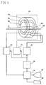
- Figure 2 shows a block diagram of a magnetic resonance imaging apparatus, which is an embodiment of the present invention.
- the configuration of the apparatus represents an embodiment of the apparatus in accordance with the present invention, and the operation of the apparatus represents an embodiment of the method in accordance with the present invention.
- the present apparatus has a magnet system 100.
- the magnet system 100 has a main magnetic field coil section 102, a gradient coil section 106 and an RF (radio frequency) coil section 108. These coil sections have a generally cylindrical outer shape and are concentrically disposed.
- An imaged object 300 is rested on a cradle 500 and carried into and out of the internal space of the magnet system 100 by carrier means (not shown).
- the main magnetic field coil section 102 generates a static magnetic field in the internal space of the magnet system 100.
- the direction of the static magnetic field is generally in parallel with the body axis of the imaged object 300, i.e., a "horizontal" magnetic field is generated.
- the main magnetic field coil section 102 is made using a superconductive coil, for example. It will be easily recognized that the main magnetic field coil section 102 is not limited to a superconductive coil, but may be made using a normal conductive coil or the like.
- the gradient coil section 106 generates gradient magnetic fields for imparting gradients to the static magnet field strength.
- the gradient magnetic fields to be generated include two slice gradient magnetic fields and a readout gradient magnetic field.
- the two slice gradient magnetic fields have respective gradients in directions orthogonal to each other.
- the readout gradient magnetic field has a gradient in a direction orthogonal to the two slice gradient directions.
- the gradient coil section 106 has three gradient coils (not shown) corresponding to these three gradient magnetic fields.
- a gradient magnetic field is referred to simply as a gradient hereinbelow.
- the RF coil section 108 generates a high frequency magnetic field in the static magnetic field space to excite spins within the imaged object 300.
- the generation of the high frequency magnetic field will be referred to as transmission of an RF excitation signal hereinbelow.
- the RF coil section 108 also receives an electromagnetic wave generated by the excited spins, i.e., a magnetic resonance signal.
- the RF coil section 108 has a transmit coil and a receive coil (not shown).
- the transmit and receive coils are either the same coil or separate dedicated coils.
- the gradient coil section 106 is connected with a gradient driving section 130 for supplying driving signals to the gradient coil section 106 to generate the gradient magnetic fields.
- the gradient driving section 130 has three driving circuits (not shown) corresponding to the three gradient coils in the gradient coil section 106.
- the RF coil section 108 is connected with an RF driving section 140 for supplying driving signals to the RF coil section 108 to transmit the RF excitation signals, thereby exciting the spins within the imaged object 300.
- the RF coil section 108 is also connected with a data acquisition section 150 for gathering signals received by the RF coil section 108 and acquiring the signals as digital data.
- the gradient driving section 130, RF driving section 140 and data acquisition section 150 are connected with a control section 160 for controlling these sections 130 ⁇ 150.
- a portion consisting of the main magnetic field coil section 102, gradient coil section 106, gradient driving section 130, RF coil section 108, data acquisition section 150 and control section 160 is an embodiment of the magnetic resonance signal receiving apparatus of the present invention.
- the configuration of the apparatus represents an embodiment of the apparatus in accordance with the present invention, and the operation of the apparatus represents an embodiment of the method in accordance with the present invention.
- a portion consisting of the main magnetic field coil section 102, gradient coil section 106, gradient driving section 130 and control section 160 is an embodiment of the gradient magnetic field applying means of the present invention.
- the data acquisition section 150 is connected to a data processing section 170.
- the data processing section 170 stores data gathered from the data acquisition section 150 in a memory (not shown).
- the data processing section 170 reconstructs a tomographic image of the imaged object 300 using the data stored in the memory.
- the data processing section 170 is connected to the control section 160.
- the data processing section 170 is above the control section 160 and controls the section 160.
- the data processing section 170 is connected with a display section 180 that displays the reconstructed image and several kinds of information output from the data processing section 170, and an operating section 190 that is operated by a human operator and inputs several commands, information and so forth to the data processing section 170.
- Figure 3 shows a block diagram of another magnetic resonance imaging apparatus, which is an embodiment of the present invention.
- the configuration of the apparatus represents an embodiment of the apparatus in accordance with the present invention, and the operation of the apparatus represents an embodiment of the method in accordance with the present invention.
- the apparatus shown in Fig. 3 has a different magnet system 100' from the apparatus shown in Fig. 2. Components other than the magnet system 100' are configured similarly to those in the apparatus shown in Fig. 2. Similar parts are designated by similar reference numerals and explanation thereof will be omitted.
- the magnet system 100' has a main magnetic field magnet section 102', a gradient coil section 106' and an RF coil section 108'.
- the main magnetic field magnet section 102' and the coil sections 106' and 108' each comprises a pair of members facing each other across a space. These sections have a generally disk-like outer shape and are disposed to have a common center axis.
- the imaged object 300 is rested on the cradle 500 and carried into and out of the internal space of the magnet system 100' by carrier means (not shown).
- the main magnetic field magnet section 102' generates a static magnetic field in the internal space of the magnet system 100'.
- the direction of the static magnetic field is generally orthogonal to the direction of the body axis of the imaged object 300, i.e., a "vertical" magnetic field is generated.
- the main magnetic field magnet section 102' is made using a permanent magnet, for example. It will be easily recognized that the main magnetic field magnet section 102' is not limited to a permanent magnet, but may be made using a superconductive or normal conductive electromagnet, etc.
- the gradient coil section 106' generates gradient magnetic fields for imparting gradients to the static magnet field strength.
- the gradient magnetic fields to be generated include two slice gradient magnetic fields and a readout gradient magnetic field.
- the two slice gradient magnetic fields have respective gradients in directions orthogonal to each other.
- the readout gradient magnetic field has a gradient in a direction orthogonal to the two slice gradient directions.
- the gradient coil section 106' has three gradient coils (not shown) corresponding to these three gradient magnetic fields.
- the RF coil section 108' transmits an RF excitation signal to the static magnetic field space to excite spins within the imaged object 300.
- the RF coil section 108' also receives a magnetic resonance signal generated by the excited spins.
- the RF coil section 108' has a transmit coil and a receive coil (not shown). The transmit and receive coils are either the same coil or separate dedicated coils.
- Figure 4 shows an exemplary pulse sequence for use in magnetic resonance imaging.
- the illustrated pulse sequence is based on a line scanning pulse sequence.
- (1) is a sequence of a 90° pulse and a 180° pulse for RF excitation in line scanning
- (2), (3), (4) and (5) are sequences of slice gradients Gs1 and Gs2, a readout gradient Gr, and a spin echo MR in line scanning, respectively.
- the 90° and 180° pulses are represented by their respective center signals.
- the pulse sequence proceeds from the left to the right along a time axis t.
- the 90° pulse produces 90° excitation of the spins.
- the slice gradients Gs1 and Gs2 are simultaneously applied to selectively excite the slice 90a, for example, as shown in Fig. 1, by 90°.
- 180° excitation by the 180° pulse is achieved.
- the slice gradients Gs1 and Gs2 are simultaneously applied to selectively excite by 180° the slice 180a that intersects the slice 90a.
- the spins are dephased by the readout gradient Gr. Thereafter, the spins are rephased by the readout gradient Gr. Accompanying the rephasing, the spins inverted in the linear region aa generate a spin echo MR.
- the spin echo MR is an RF signal having a symmetric waveform with respect to the echo center.
- the central echo occurs after a time TE (echo time) from the 90° excitation.
- the spin echo MR is received at the RF coil section 108, and the received signal is collected as line data by the data acquisition section 150.
- the slice gradient Gs1 and Gs2 are simultaneously applied, thereby fully dephasing the spins within the imaged space. That is, gradient magnetic fields, generally referred to as killer gradients or crusher gradients, are applied.
- killer gradients or crusher gradients are applied.
- the application of such a killer or crusher gradient differentiates the line scanning pulse sequence from an ordinary one. These gradients are referred to simply as killers hereinbelow.
- Such a pulse sequence is repeated about, for example, 64 ⁇ 512 times in a cycle of TR (repetition time).
- the slice gradients Gs1 and Gs2 are varied for each repetition, and selective excitation is performed on a combination of slices.
- 64 [dash] ⁇ 512 line data, such as bb, cc, dd..., are sequentially obtained.
- the strengths of the killers Gs1k and Gs2k are varied for each repetition. Moreover, the variation in the killers Gs1k and Gs2k are selected so as not to have substantial periodicity.
- Figure 5 shows an example of the killer strength variation given by Eq. (1). Since an irrational number is employed as the coefficient ⁇ , the values of killers Gs1k and Gs2k are prevented from repeating themselves even if the repetition is infinitely continued, It should be noted that the killer strengths may instead be varied based on random numbers.
- the killer strength By varying the killer strength each repetition, it is possible to avoid problems that occur when the killer strength is the same each time. Specifically, as shown in Fig. 6, if the killer strength is the same each time, 90° excited spins once dephased by the killer in a period TR1 are rewound, or rephased by a killer applied after 180° excitation in a period TR2.
- the killer since the killer has the same strength before and after the 180° excitation, the amount of dephasing and the amount of rephasing become the same, and a spin echo mr will be generated after te from the 90° excitation in the period TR1.
- the spin echo mr overlaps a proper spin echo in a period TR3, resulting in artifacts.
- the present apparatus Since the present apparatus varies the killer strength every time, such a problem can be avoided. However, even if the killer is varied each time, when the killer strength has periodicity, the amounts of dephasing and rephasing become the same between first and second cycles of such periodicity, which may result in a similar unwanted spin echo. Accordingly, the present apparatus eliminates any periodicity and prevents such a problem.
- a spin echo is thus acquired for each line without incorporating unwanted signals.
- the line data are collected in the memory in the data processing section 170.
- the data processing section 170 performs a one-dimensional inverse Fourier transformation on the line data to reconstruct respective line images, which are arranged in parallel to produce a tomographic image of the imaged object 300.
- the reconstructed image has good quality not containing artifacts.
- Such an image of good quality is displayed by the display section 180 as a visible image.
Landscapes
- Physics & Mathematics (AREA)
- Health & Medical Sciences (AREA)
- Nuclear Medicine, Radiotherapy & Molecular Imaging (AREA)
- Life Sciences & Earth Sciences (AREA)
- General Health & Medical Sciences (AREA)
- Radiology & Medical Imaging (AREA)
- Engineering & Computer Science (AREA)
- High Energy & Nuclear Physics (AREA)
- Signal Processing (AREA)
- General Physics & Mathematics (AREA)
- Condensed Matter Physics & Semiconductors (AREA)
- Medical Informatics (AREA)
- Pathology (AREA)
- Biomedical Technology (AREA)
- Heart & Thoracic Surgery (AREA)
- Biophysics (AREA)
- Molecular Biology (AREA)
- Surgery (AREA)
- Animal Behavior & Ethology (AREA)
- Public Health (AREA)
- Veterinary Medicine (AREA)
- Magnetic Resonance Imaging Apparatus (AREA)
Applications Claiming Priority (2)
| Application Number | Priority Date | Filing Date | Title |
|---|---|---|---|
| JP24096199A JP3342853B2 (ja) | 1999-08-27 | 1999-08-27 | 磁気共鳴撮像装置 |
| JP24096199 | 1999-08-27 |
Publications (2)
| Publication Number | Publication Date |
|---|---|
| EP1081502A2 true EP1081502A2 (fr) | 2001-03-07 |
| EP1081502A3 EP1081502A3 (fr) | 2003-04-02 |
Family
ID=17067240
Family Applications (1)
| Application Number | Title | Priority Date | Filing Date |
|---|---|---|---|
| EP00307140A Ceased EP1081502A3 (fr) | 1999-08-27 | 2000-08-21 | Suppression de faux échos de spin en résonance magnétique à balayage de lignes |
Country Status (6)
| Country | Link |
|---|---|
| US (1) | US6479995B1 (fr) |
| EP (1) | EP1081502A3 (fr) |
| JP (1) | JP3342853B2 (fr) |
| KR (1) | KR100430941B1 (fr) |
| CN (1) | CN1286069A (fr) |
| BR (1) | BR0003626A (fr) |
Families Citing this family (10)
| Publication number | Priority date | Publication date | Assignee | Title |
|---|---|---|---|---|
| JP3796455B2 (ja) * | 2002-02-22 | 2006-07-12 | ジーイー・メディカル・システムズ・グローバル・テクノロジー・カンパニー・エルエルシー | Mri装置 |
| US20030210044A1 (en) * | 2002-05-13 | 2003-11-13 | Ken-Pin Hwang | Missing pulse steady state free precession |
| EP1504274B1 (fr) * | 2002-05-15 | 2008-03-05 | Siemens Aktiengesellschaft | Appareil a resonance magnetique |
| JP3938740B2 (ja) * | 2002-10-10 | 2007-06-27 | ジーイー・メディカル・システムズ・グローバル・テクノロジー・カンパニー・エルエルシー | Mr画像生成方法およびmri装置 |
| JP4273138B2 (ja) | 2006-06-30 | 2009-06-03 | ジーイー・メディカル・システムズ・グローバル・テクノロジー・カンパニー・エルエルシー | 磁気共鳴撮像装置及び磁気共鳴受信装置 |
| JP5022696B2 (ja) * | 2006-12-22 | 2012-09-12 | ジーイー・メディカル・システムズ・グローバル・テクノロジー・カンパニー・エルエルシー | 磁気共鳴イメージング装置 |
| JP5063279B2 (ja) * | 2007-09-27 | 2012-10-31 | 株式会社日立製作所 | 磁気共鳴装置 |
| WO2010043997A1 (fr) * | 2008-10-13 | 2010-04-22 | Koninklijke Philips Electronics N.V. | Impulsion de préparation à la magnétisation insensible de flux pour contraste t2* |
| KR101036279B1 (ko) * | 2009-12-10 | 2011-05-23 | 최희택 | 집배수시설용 침투식 비점오염 정화장치 |
| JP6946296B2 (ja) * | 2015-12-16 | 2021-10-06 | コーニンクレッカ フィリップス エヌ ヴェKoninklijke Philips N.V. | 磁気共鳴イメージング(mri)システムのための無線通信のためのシステム及び方法 |
Family Cites Families (6)
| Publication number | Priority date | Publication date | Assignee | Title |
|---|---|---|---|---|
| FR2526968B1 (fr) | 1982-05-14 | 1986-02-28 | Thomson Csf | Procede de tomographie d'un objet par resonance magnetique nucleaire |
| DE4205780C2 (de) * | 1992-02-26 | 1995-02-16 | Spectrospin Ag | Verfahren zur Erzeugung von NMR-Signalen mit kohärentem Phasenprofil durch Kombination von Hochfrequenzimpulsen mit inkohärentem Phasenprofil |
| US5311133A (en) * | 1992-10-05 | 1994-05-10 | Picker International, Inc. | Concurrent generation of multiple images in fast (TR<T2) scanning sequences |
| JPH08103427A (ja) | 1994-10-06 | 1996-04-23 | Toshiba Corp | 磁気共鳴イメージング装置 |
| DE19511794B4 (de) | 1995-03-30 | 2005-12-29 | Siemens Ag | Verfahren zur Gewinnung von Bilddaten in einem Kernspintomographiegerät und Kernspintomographiegerät zur Durchführung des Verfahrens |
| US5786692A (en) * | 1995-08-18 | 1998-07-28 | Brigham And Women's Hospital, Inc. | Line scan diffusion imaging |
-
1999
- 1999-08-27 JP JP24096199A patent/JP3342853B2/ja not_active Expired - Fee Related
-
2000
- 2000-06-20 US US09/597,526 patent/US6479995B1/en not_active Expired - Fee Related
- 2000-08-16 BR BR0003626-9A patent/BR0003626A/pt not_active IP Right Cessation
- 2000-08-17 CN CN00124279A patent/CN1286069A/zh active Pending
- 2000-08-21 EP EP00307140A patent/EP1081502A3/fr not_active Ceased
- 2000-08-21 KR KR10-2000-0048249A patent/KR100430941B1/ko not_active Expired - Fee Related
Also Published As
| Publication number | Publication date |
|---|---|
| EP1081502A3 (fr) | 2003-04-02 |
| US6479995B1 (en) | 2002-11-12 |
| KR100430941B1 (ko) | 2004-05-12 |
| JP3342853B2 (ja) | 2002-11-11 |
| CN1286069A (zh) | 2001-03-07 |
| JP2001061810A (ja) | 2001-03-13 |
| BR0003626A (pt) | 2001-04-03 |
| KR20010067090A (ko) | 2001-07-12 |
Similar Documents
| Publication | Publication Date | Title |
|---|---|---|
| US4521733A (en) | NMR Imaging of the transverse relaxation time using multiple spin echo sequences | |
| EP0135847B1 (fr) | Procédé de formation d'images par résonance magnétique nucléaire utilisant des séquences d'impulsions combinant l'excitation sélective et la précession libre commandée | |
| US5704357A (en) | Method of producing MR image and MRI system | |
| EP0413511A2 (fr) | Imagerie pour résonance magnétique nucléaire | |
| US5537039A (en) | Virtual frequency encoding of acquired NMR image data | |
| KR100405922B1 (ko) | 구배 자장 인가 방법 및 장치, 및 자기 공명 촬상 장치 | |
| US20010004211A1 (en) | Magnetic resonance imaging apparatus | |
| US6515477B1 (en) | Magnetic resonance random trajectory collection method and apparatus | |
| US5043665A (en) | Magnetic resonance imaging system | |
| EP1081502A2 (fr) | Suppression de faux échos de spin en résonance magnétique à balayage de lignes | |
| US6147493A (en) | Magnetic resonance imaging method and apparatus | |
| JP2642362B2 (ja) | 磁気共鳴映像装置 | |
| US5241271A (en) | Ultra-fast imaging method and apparatus | |
| EP1191347A2 (fr) | Poursuite de la fréquence de résonance des spins dans la résonance magnétique | |
| US5684400A (en) | Diffusion sensitizing imaging method, dynamic imaging method, and MRI apparatus | |
| US4792758A (en) | Steady-state echo magnetic resonance imaging | |
| KR20030007062A (ko) | 스핀 여기 방법, 자기 공명 촬영 방법 및 자기 공명 촬영시스템 | |
| KR100559345B1 (ko) | 자기 공명 신호 획득 방법 및 장치, 기록 매체 및 자기공명 촬영 장치 | |
| US5672970A (en) | Magnetic-resonance imaging apparatus | |
| EP0753759A1 (fr) | Méthode d'imagerie sensible à la diffusion, méthode dynamique d'imagerie et appareil d'IRM | |
| US6181133B1 (en) | Magnetic resonance imaging of fluid flows using echo-planar technology | |
| JP3770562B2 (ja) | 磁気共鳴イメージング装置 | |
| JPH07178067A (ja) | 磁気共鳴イメージング装置 | |
| JPH11225982A (ja) | 磁気共鳴イメージング装置 | |
| JPH0614915B2 (ja) | 磁気共鳴イメージング装置 |
Legal Events
| Date | Code | Title | Description |
|---|---|---|---|
| PUAI | Public reference made under article 153(3) epc to a published international application that has entered the european phase |
Free format text: ORIGINAL CODE: 0009012 |
|
| AK | Designated contracting states |
Kind code of ref document: A2 Designated state(s): AT BE CH CY DE DK ES FI FR GB GR IE IT LI LU MC NL PT SE |
|
| AX | Request for extension of the european patent |
Free format text: AL;LT;LV;MK;RO;SI |
|
| PUAL | Search report despatched |
Free format text: ORIGINAL CODE: 0009013 |
|
| AK | Designated contracting states |
Kind code of ref document: A3 Designated state(s): AT BE CH CY DE DK ES FI FR GB GR IE IT LI LU MC NL PT SE Designated state(s): AT BE CH CY DE DK ES FI FR GB GR IE IT LI LU MC NL PT SE |
|
| AX | Request for extension of the european patent |
Extension state: AL LT LV MK RO SI |
|
| RIC1 | Information provided on ipc code assigned before grant |
Ipc: 7G 01R 33/54 A |
|
| 17P | Request for examination filed |
Effective date: 20031002 |
|
| AKX | Designation fees paid |
Designated state(s): DE FR GB |
|
| 17Q | First examination report despatched |
Effective date: 20070103 |
|
| STAA | Information on the status of an ep patent application or granted ep patent |
Free format text: STATUS: THE APPLICATION HAS BEEN REFUSED |
|
| 18R | Application refused |
Effective date: 20070909 |