EP1081726A2 - Mehrpoliges Schaltgerät - Google Patents
Mehrpoliges Schaltgerät Download PDFInfo
- Publication number
- EP1081726A2 EP1081726A2 EP00890259A EP00890259A EP1081726A2 EP 1081726 A2 EP1081726 A2 EP 1081726A2 EP 00890259 A EP00890259 A EP 00890259A EP 00890259 A EP00890259 A EP 00890259A EP 1081726 A2 EP1081726 A2 EP 1081726A2
- Authority
- EP
- European Patent Office
- Prior art keywords
- rails
- pole
- contact pieces
- area
- conductor
- Prior art date
- Legal status (The legal status is an assumption and is not a legal conclusion. Google has not performed a legal analysis and makes no representation as to the accuracy of the status listed.)
- Granted
Links
- 230000005405 multipole Effects 0.000 title claims abstract description 18
- 239000004020 conductor Substances 0.000 claims description 70
- 230000007935 neutral effect Effects 0.000 claims description 11
- 238000011156 evaluation Methods 0.000 claims description 6
- 238000004804 winding Methods 0.000 claims description 5
- 238000001514 detection method Methods 0.000 claims description 4
- 241000283973 Oryctolagus cuniculus Species 0.000 claims 1
- 230000003321 amplification Effects 0.000 description 6
- 238000003199 nucleic acid amplification method Methods 0.000 description 6
- 238000010791 quenching Methods 0.000 description 6
- 230000000171 quenching effect Effects 0.000 description 6
- 238000013461 design Methods 0.000 description 3
- 230000000694 effects Effects 0.000 description 3
- 238000005192 partition Methods 0.000 description 3
- 230000002787 reinforcement Effects 0.000 description 3
- 230000005672 electromagnetic field Effects 0.000 description 2
- 238000012423 maintenance Methods 0.000 description 2
- 230000001133 acceleration Effects 0.000 description 1
- 230000005611 electricity Effects 0.000 description 1
- 230000002349 favourable effect Effects 0.000 description 1
- 238000003780 insertion Methods 0.000 description 1
- 230000037431 insertion Effects 0.000 description 1
- 239000000463 material Substances 0.000 description 1
- 238000000034 method Methods 0.000 description 1
- 238000012986 modification Methods 0.000 description 1
- 230000004048 modification Effects 0.000 description 1
- 230000001960 triggered effect Effects 0.000 description 1
Images





Classifications
-
- F—MECHANICAL ENGINEERING; LIGHTING; HEATING; WEAPONS; BLASTING
- F23—COMBUSTION APPARATUS; COMBUSTION PROCESSES
- F23D—BURNERS
- F23D14/00—Burners for combustion of a gas, e.g. of a gas stored under pressure as a liquid
- F23D14/20—Non-premix gas burners, i.e. in which gaseous fuel is mixed with combustion air on arrival at the combustion zone
- F23D14/22—Non-premix gas burners, i.e. in which gaseous fuel is mixed with combustion air on arrival at the combustion zone with separate air and gas feed ducts, e.g. with ducts running parallel or crossing each other
-
- F—MECHANICAL ENGINEERING; LIGHTING; HEATING; WEAPONS; BLASTING
- F23—COMBUSTION APPARATUS; COMBUSTION PROCESSES
- F23D—BURNERS
- F23D14/00—Burners for combustion of a gas, e.g. of a gas stored under pressure as a liquid
- F23D14/32—Burners for combustion of a gas, e.g. of a gas stored under pressure as a liquid using a mixture of gaseous fuel and pure oxygen or oxygen-enriched air
-
- H—ELECTRICITY
- H01—ELECTRIC ELEMENTS
- H01H—ELECTRIC SWITCHES; RELAYS; SELECTORS; EMERGENCY PROTECTIVE DEVICES
- H01H83/00—Protective switches, e.g. circuit-breaking switches, or protective relays operated by abnormal electrical conditions otherwise than solely by excess current
- H01H83/20—Protective switches, e.g. circuit-breaking switches, or protective relays operated by abnormal electrical conditions otherwise than solely by excess current operated by excess current as well as by some other abnormal electrical condition
- H01H83/22—Protective switches, e.g. circuit-breaking switches, or protective relays operated by abnormal electrical conditions otherwise than solely by excess current operated by excess current as well as by some other abnormal electrical condition the other condition being imbalance of two or more currents or voltages
- H01H83/226—Protective switches, e.g. circuit-breaking switches, or protective relays operated by abnormal electrical conditions otherwise than solely by excess current operated by excess current as well as by some other abnormal electrical condition the other condition being imbalance of two or more currents or voltages with differential transformer
-
- H—ELECTRICITY
- H01—ELECTRIC ELEMENTS
- H01H—ELECTRIC SWITCHES; RELAYS; SELECTORS; EMERGENCY PROTECTIVE DEVICES
- H01H9/00—Details of switching devices, not covered by groups H01H1/00 - H01H7/00
- H01H9/30—Means for extinguishing or preventing arc between current-carrying parts
- H01H9/44—Means for extinguishing or preventing arc between current-carrying parts using blow-out magnet
-
- F—MECHANICAL ENGINEERING; LIGHTING; HEATING; WEAPONS; BLASTING
- F23—COMBUSTION APPARATUS; COMBUSTION PROCESSES
- F23L—SUPPLYING AIR OR NON-COMBUSTIBLE LIQUIDS OR GASES TO COMBUSTION APPARATUS IN GENERAL ; VALVES OR DAMPERS SPECIALLY ADAPTED FOR CONTROLLING AIR SUPPLY OR DRAUGHT IN COMBUSTION APPARATUS; INDUCING DRAUGHT IN COMBUSTION APPARATUS; TOPS FOR CHIMNEYS OR VENTILATING SHAFTS; TERMINALS FOR FLUES
- F23L2900/00—Special arrangements for supplying or treating air or oxidant for combustion; Injecting inert gas, water or steam into the combustion chamber
- F23L2900/07002—Injecting inert gas, other than steam or evaporated water, into the combustion chambers
Definitions
- the invention relates to a multi-pole switching device, in which each pole section at least has an input terminal and an output terminal, which via a Connection line are electrically connected to each other and at least one Measuring device for detecting the current flowing in this connecting line is provided, at least one pole section being provided, in the connecting line thereof a switching contact with a fixed and a movable contact piece switched is to which contact pieces are electrically conductive, between the contact pieces Connect arcs that arise from these contact pieces to conductors.
- the connecting line at least one Pole path, which is adjacent to the pole path having the switch contact at least is performed in sections so that that generated by the current flowing in it during operation Magnetic field reinforces that magnetic field which is in the contact pieces and the Rails circumscribed area of which when there is an arc between the Contact pieces or the rails in the rails and the current flowing in the arc is caused.
- the connecting line between the input and output terminal of a pole section is a already existing component of the switching device, which is only for realizing the invention needs to be slightly modified.
- This modification lies in the insertion of a Line piece, e.g. Conductor rope, or if such in the connecting line already exists, in changing its spatial arrangement, which if necessary, can be accompanied by a slight extension of this conductor cable. All in all, however, all of these measures result in only a minimal additional material expenditure and can easily be built into existing designs from Switchgear can be installed.
- the connecting line at least in sections approximately parallel to that circumscribed by the contact pieces and the rails Area in the area of which the border runs.
- the magnetic field caused by the current in the connecting line thus runs in the same direction as that generated by the current in the rails and the arc Magnetic field, so that the amplification of this magnetic field to be achieved is particularly effective is achieved.
- the connecting line in the form of a conductor loop and so is arranged that the area spanned by it approximately parallel to that of the contact pieces and the area circumscribed by the rails, and this area at least in some areas covered.
- the conductor loop spanned area is the area circumscribed by the contact pieces and the rails at least in the area of the contact pieces and in the area of those immediately adjacent to them Sections of the rails covered.
- Another object of the present invention is to provide a multi-pole switching device two pole sections designed as a combination of miniature circuit breaker and Residual current circuit breaker to specify, in which this has so far been general and not on certain multi-pole switching device realized limited inventive principle is.
- the first one for connecting the phase conductor single-phase voltage supply network provided pole section the measuring devices a circuit breaker (overcurrent detector and short-circuit current detector) and a switching contact controlled by these measuring devices via a switching mechanism and to the fixed or the movable contact piece of this switching contact subsequent, electrically conductive rails and has the second for connecting the Neutral conductor of a single-phase voltage supply network provided the pole section Components of a residual current detection circuit (summation current transformer and on its Secondary winding connected evaluation circuit).
- the connecting lines both this neutral conductor pole section as well as the phase conductor pole section are through the toroid of the total current transformer and the evaluation device acts on the in the Phase conductor pole path arranged switching mechanism.
- the connecting line of the neutral conductor pole section is formed by a conductor cable which in Shape of a conductor loop and is arranged so that the spanned by it Surface approximately parallel to the surface circumscribed by the contact pieces and the rails lies and this area at least in the area of the contact pieces and in the area of these immediately adjacent sections of the rails covered.
- 1 and 2 denote electrically conductive, current-carrying rails, between which an arc 3 burns.
- the current through the rails 1,2 and Arc 3 generates an electromagnetic field, the direction of which is represented by symbols 4 and 5 is shown.
- the arc 3 is located within this field current-carrying conductor on which this electromagnetic field exerts a force F. This force F shifts the arc 3 in its direction, that is to the right in the Representation according to FIG. 1.
- a spark extinguishing chamber 6 As shown in Fig.1.
- Such a facility comprises a plurality of approximately parallel plates 7 which are approximately normal to Arc 3 are aligned. If the arc 3 runs into such a spark quenching chamber 6 into the plate 7 into a plurality of partial arcs connected in series divided, which are pending between the plates 7.
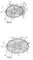
- a current-carrying conductor 10 is provided, which in sections runs approximately parallel to the area A 1 circumscribed by the contact pieces 8, 9 and the rails 1 , 2 (cf. FIGS. 3a, b, c).
- the current flow in this conductor 10 generates a magnetic field represented by the symbols 4 ', 5', which is superimposed on the magnetic field prevailing within the area A 1 . If the current flow direction in the conductor 10 is selected in the manner shown in FIGS. 3a, b, c, the magnetic field in the area A 1 is amplified.
- the exact course of the conductor 10 is to be selected so that the discussed effect of the magnetic field amplification results.
- This conductor 10 can therefore be arranged anywhere in the area outside the area A 1 (cf. FIGS. 3a, b, c). The closer it is to the area A 1 , the greater is of course the effect which strengthens the magnetic field in this area A 1 , which is why it is preferably arranged in the area of the boundary, for example at a short distance exactly above one of the rails 1 , 2.
- a conductor loop 11 is used, which is arranged such that the area A 2 spanned by it is approximately parallel to that of the contact pieces 8, 9 and the rails 1, 2 circumscribed area A 1 and this area A 1 at least partially covers.
- the conductor loop 11 is therefore coplanar over the area A 1 .
- the magnetic field driving the arc 3 in the direction of the spark quenching chamber 6 is strengthened. Outside of this coverage area, the magnetic field generated by the conductor loop 11 weakens the magnetic field generated by rails 1, 2 and arc, which in itself leads to a lower running speed of the arc 3 in this area.
- this area lying outside the coverage area of the areas A 1 and A 2 is already in the spark quenching chamber 6, that is to say in an area in which the arc 3 is already about to be extinguished and therefore no longer in any case must be moved.
- the cheapest design variant of the conductor loop 11, taking into account the information just given, is of course to cover the entire area A 1 (see FIG. 4b).
- the number of turns of the conductor loop 11 can be chosen to be as high as desired, however only small forces are required to move an arc 3, it is sufficient as shown in Fig.4a, b to provide a single winding.
- the invention relies on the provision of a discussed conductor 10 and a discussed Conductor loop 11 to increase the running speed of an arc 3 and is in applying this principle to a multi-pole switching device.
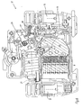
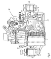
- An example of a such a multi-pole switching device is shown in Figs. 5-9, to which reference is made below is taken:
- This multi-pole switching device has two poles and is a combination of a circuit breaker and residual current circuit breaker.
- Each pole section 12, 13 has at least one Input terminal 14, 14 'and an output terminal 15, 15'.
- the input terminal 14, 14 ' each pole section 12, 13 is connected to the output terminal 15, 15 'of this pole section 12, 13 Connection line electrically connected.
- the coil 20 has an armature which is displaceable in its longitudinal direction and which from the magnetic field of the coil 20 - if this is due to a short-circuit current has sufficient strength - is pressed against the contact bridge 18 so that the Switching mechanism 26 triggered and by this the contact bridge 18 is pivoted. Ultimately, through these processes, the movable contact piece 9 becomes stationary Contact piece 8 lifted off.
- the coil 20 with the movable armature forms the Short circuit current detector of the circuit breaker part of the present switching device.
- the bimetallic strip 16 is heated by the current flowing through it and bends so that its end connected to the conductor cable 17 is pivoted to the right. If the continuous current is too high, this bend of the bimetal strip 16 leads to the extent that that the contact bridge 18 is pivoted via the bracket 22 and the movable contact piece 9 is lifted off the fixed contact piece 8.
- the bimetallic strip 16 thus forms the Overcurrent detector of the circuit breaker part of the present switching device.
- This pole section 12 is thus two the current through this connecting line measuring devices and a switch contact (fixed and movable Contact piece 8.9), on which said two current measuring devices act, i.e. can open it.
- electrically conductive rails 1, 2 are provided, which contact the contact pieces Connect 8.9 and serve to create arcs between the contact pieces 8.9 to lead away from these.
- electrically conductive rails 1, 2 In the space between these rails 1, 2 there is a large number of spaced parallel electrically conductive plates 7 are provided, which forms a spark extinguishing chamber 6 with the functional principle already discussed above.
- the electronics are also included connected to the moving contact piece 9 switching mechanism, so that it upon detection of an impermissibly high difference between the currents in the conductor cables 21 and 23 cause the interruption contact 8, 9 of the first pole section 12 to open can.
- the second pole section 13 thus contained the components of a fault current detection circuit, formed from a summation current transformer and one of them Secondary winding of connected evaluation circuit. This evaluation circuit can naturally in a different form, for example by means of a permanent magnet release, be realized.
- the conductor cable 23 forming the connecting line between the input terminal 14 'and the output terminal 15' is designed in the form of a conductor loop which has one turn.
- This conductor loop is arranged in such a way that the area A 2 spanned by it lies approximately parallel to the area A 1 circumscribed by the contact pieces 8, 9 and the rails 1, 2 and covers this area A 1 in some areas.
- the first pole section 12 is for connecting the phase conductor L of a two-pole voltage supply network, the second pole section 13 for connecting the neutral conductor N this Voltage supply network provided. Occurs when the switch contact opens Arc between its contact pieces 8.9 or subsequently between them Components connecting rails 1,2, this arc ensures that initially also current still flows in neutral conductor N and thus in conductor cable 23. This current flow therefore leads for the amplification of the magnetic field discussed in the beginning, which in the Contact pieces 8.9 and the rails 1.2 circumscribed area in the presence of a Arc between the contact pieces 8.9 and the rails 1.2 from in the rails 1,2 and the arc flowing current is caused.
- the invention is by no means limited to that shown in FIGS. 6-9, particularly preferred Embodiment limited.
- the principle on which it is based is that of an in any designed multi-pole switching device that the above with reference to Fig.1-4b discussed principle of increasing the arc running speed with the help of an anyway existing connecting line of a pole path that is adjacent to a Switching contact with subsequent pole section containing arc quenching device lies to realize.
- the connecting line does not have the shape of a conductor loop must have only one turn, several turns could also be provided. It but is also sufficient in the sense of FIGS. 3a-c, only a section of that in FIGS provided conductor loop.
- the remaining sections of the conductor rope 23 can be laid as desired.
- the Input terminal 14 'of the neutral conductor pole section 13 at the lower edge of the device that is to be arranged next to the input terminal 14 of the phase conductor pole section 12. It is enough to effect the magnetic field reinforcement in question, the conductor cable 23 in the form of in FIG. 9 with the 23 'upper branch or the lower branch with 23 " Lay the conductor loop.
- the application of the present invention is not limited to switching devices, where circuit breaker and residual current circuit breaker functions are combined. Rather, it is possible to use the principle according to the invention with a multipole, only one of the two circuit breaker functions (three- or four-pole Miniature circuit breakers or four-pole residual current circuit breakers, each for one three-phase three-phase system).
- a switch contact with an arc extinguishing device is not only in one of the Pole sections, but at least in all phase conductor pole sections, usually also in the Neutral conductor pole section may be provided.
- This prevents the application of the objective Not invention, also here the connecting line of one of the pole sections in one of the The ways discussed above are such that the current flow in this connecting line that magnetic field is amplified, the one between the rails 1, 2 of an adjacent one Pole path moving arc moving.
- the neutral conductor N can also be designed to be interruptible here, i.e. in its pole section 13 a switch contact corresponding to the design of the first pole section 12 can be installed.
Landscapes
- Engineering & Computer Science (AREA)
- Chemical & Material Sciences (AREA)
- Combustion & Propulsion (AREA)
- Mechanical Engineering (AREA)
- General Engineering & Computer Science (AREA)
- Power Engineering (AREA)
- Arc-Extinguishing Devices That Are Switches (AREA)
- Breakers (AREA)
- Keying Circuit Devices (AREA)
- Measuring Magnetic Variables (AREA)
- Train Traffic Observation, Control, And Security (AREA)
- Percussion Or Vibration Massage (AREA)
- Valve Device For Special Equipments (AREA)
- Control Of Eletrric Generators (AREA)
- Railway Tracks (AREA)
- Interface Circuits In Exchanges (AREA)
- Control Of Motors That Do Not Use Commutators (AREA)
- Navigation (AREA)
Abstract
Description
Claims (6)
- Mehrpoliges Schaltgerät, bei welchem jede Polstrecke (12,13) zumindest eine Eingangsklemme (14,14') und eine Ausgangsklemme (15,15') aufweist, welche über eine Verbindungsleitung elektrisch miteinander verbunden sind und zumindest eine Meßeinrichtung zur Erfassung des in dieser Verbindungsleitung fließenden Stromes vorgesehen ist, wobei zumindest eine Polstrecke (12) vorgesehen ist, in deren Verbindungsleitung ein Schaltkontakt mit einem feststehenden (8) und einem beweglichen Kontaktstück (9) geschaltet ist, an welche Kontaktstücke (8,9) sich elektrisch leitende, zwischen den Kontaktstücken (8,9) entstehende Lichtbögen (3) von diesen Kontaktstücken (8,9) wegleitende Schienen (1,2) anschließen, dadurch gekennzeichnet, daß die Verbindungsleitung zumindest einer Polstrecke (13), die benachbart zur den Schaltkontakt (8,9) aufweisenden Polstrecke (12) liegt, zumindest abschnittsweise so geführt ist, daß das von dem im Betrieb in ihr fließenden Strom erzeugte Magnetfeld jenes Magnetfeld verstärkt, welches in der von den Kontaktstücken (8,9) und den Schienen (1,2) umschriebenen Fläche (A1) von dem beim Vorliegen eines Lichtbogens (3) zwischen den Kontaktstücken (8,9) bzw. den Schienen (1,2) in den Schienen (1,2) und dem Lichtbogen (3) fließenden Strom hervorgerufen wird.
- Mehrpoliges Schaltgerät nach Anspruch 1, dadurch gekennzeichnet, daß die Verbindungsleitung zumindest abschnittsweise etwa parallel zur von den Kontaktstücken (8,9) und den Schienen (1,2) umschriebenen Fläche (A1) im Bereich deren Berandung verläuft.
- Mehrpoliges Schaltgerät nach Anspruch 1, dadurch gekennzeichnet, daß die Verbindungsleitung in Gestalt einer Leiterschleife ausgeführt und so angeordnet ist, daß die von ihr aufgespannte Fläche (A2) etwa parallel zur von den Kontaktstücken (8,9) und den Schienen (1,2) umschriebenen Fläche (A1) liegt und diese Fläche (A1) zumindest bereichsweise überdeckt.
- Mehrpoliges Schaltgerät nach Anspruch 3, dadurch gekennzeichnet, daß die von der Leiterschleife aufgespannte Fläche (A2) die von den Kontaktstücken (8,9) und den Schienen (1,2) umschriebene Fläche (A1) zumindest im Bereich der Kontaktstücke (8,9) und im Bereich der diesen unmittelbar benachbarten Abschnitten der Schienen (1,2) überdeckt.
- Mehrpoliges Schaltgerät nach Anspruch 3, dadurch gekennzeichnet, daß die Leiterschleife eine Windung aufweist.
- Mehrpoliges Schaltgerät mit zwei Polstrecken (12,13) ausgeführt als Kombination aus Leitungsschutzschalter und Fehlerstromschutzschalter, wobei die erste, zum Anschluß des Phasenleiters (L) eines einphasigen Spannungs-Versorgungsnetzes vorgesehene Polstrecke (12) die Meßeinrichtungen eines Leitungsschutzschalters (Überstromdetektor und Kurzschlußstrom-Detektor) sowie einen von diesen Meßeinrichtungen über eine Schaltmechanik (26) angesteuerten Schaltkontakt (8,9) und sich an das feststehende (8) bzw. das bewegliche Kontaktstück (9) dieses Schaltkontaktes (8,9) anschließende, elektrisch leitende Schienen (1,2) aufweist und die zweite zum Anschluß des Neutralleiters (N) eines einphasigen Spannungs-Versorgungsnetzes vorgesehene Polstrecke (13) die Komponenten einer Fehlerstrom-Erkennungsschaltung (Summenstromwandler und an dessen Sekundärwicklung angeschlossene Auswertschaltung) aufweist, wobei die Verbindungsleitungen sowohl dieser Neutralleiter-Polstrecke (13) als auch der Phasenleiter-Polstrecke (12) durch den Ringkern (24) des Summenstromwandlers geführt sind und die Auswerteinrichtung auf die in der Phasenleiter-Polstrecke (12) angeordnete Schaltmechanik (26) einwirkt, dadurch gekennzeichnet, daß die Verbindungsleitung der Neutralleiter-Polstrecke (13) durch ein Leiterseil (23) gebildet ist, das in Gestalt einer Leiterschleife ausgeführt und so angeordnet ist, daß die von ihr aufgespannte Fläche (A2) etwa parallel zur von den Kontaktstücken (8,9) und den Schienen (1,2) umschriebenen Fläche (A1) liegt und diese Fläche (A1) zumindest im Bereich der Kontaktstücke (8,9) und im Bereich der diesen unmittelbar benachbarten Abschnitten der Schienen (1,2) überdeckt.
Priority Applications (1)
| Application Number | Priority Date | Filing Date | Title |
|---|---|---|---|
| AT00890259T ATE263423T1 (de) | 1999-09-02 | 2000-08-25 | Mehrpoliges schaltgerät |
Applications Claiming Priority (2)
| Application Number | Priority Date | Filing Date | Title |
|---|---|---|---|
| AT0151599A AT411408B (de) | 1999-09-02 | 1999-09-02 | Mehrpoliges schaltgerät |
| AT151599 | 1999-09-02 |
Publications (3)
| Publication Number | Publication Date |
|---|---|
| EP1081726A2 true EP1081726A2 (de) | 2001-03-07 |
| EP1081726A3 EP1081726A3 (de) | 2002-09-11 |
| EP1081726B1 EP1081726B1 (de) | 2004-03-31 |
Family
ID=3515340
Family Applications (1)
| Application Number | Title | Priority Date | Filing Date |
|---|---|---|---|
| EP00890259A Expired - Lifetime EP1081726B1 (de) | 1999-09-02 | 2000-08-25 | Mehrpoliges Schaltgerät |
Country Status (5)
| Country | Link |
|---|---|
| EP (1) | EP1081726B1 (de) |
| AT (2) | AT411408B (de) |
| AU (1) | AU767299B2 (de) |
| CZ (1) | CZ300217B6 (de) |
| DE (1) | DE50005867D1 (de) |
Family Cites Families (6)
| Publication number | Priority date | Publication date | Assignee | Title |
|---|---|---|---|---|
| US4654614A (en) * | 1985-03-04 | 1987-03-31 | Westinghouse Electric Corp. | Current limiting solenoid operated circuit breaker |
| GB2192096B (en) * | 1986-05-31 | 1989-12-06 | Crabtree Electrical Ind Ltd | Circuit breaker |
| FR2627324B1 (fr) * | 1988-02-16 | 1995-05-12 | Merlin Gerin | Disjoncteur differentiel a neutre passant |
| DE4127291C2 (de) * | 1991-08-17 | 1996-07-11 | Abb Patent Gmbh | Lichtbogenkammer für ein elektrisches Schaltgerät |
| FR2699322B1 (fr) * | 1992-12-10 | 1995-03-17 | Merlin Gerin | Disjoncteur modulaire à courant continu. |
| DE4315485A1 (de) * | 1993-05-10 | 1994-11-17 | Abb Patent Gmbh | Elektrischer Schalter |
-
1999
- 1999-09-02 AT AT0151599A patent/AT411408B/de not_active IP Right Cessation
-
2000
- 2000-08-25 EP EP00890259A patent/EP1081726B1/de not_active Expired - Lifetime
- 2000-08-25 DE DE50005867T patent/DE50005867D1/de not_active Expired - Fee Related
- 2000-08-25 AT AT00890259T patent/ATE263423T1/de not_active IP Right Cessation
- 2000-08-31 CZ CZ20003169A patent/CZ300217B6/cs not_active IP Right Cessation
- 2000-09-01 AU AU55058/00A patent/AU767299B2/en not_active Ceased
Also Published As
| Publication number | Publication date |
|---|---|
| AT411408B (de) | 2003-12-29 |
| CZ300217B6 (cs) | 2009-03-18 |
| AU767299B2 (en) | 2003-11-06 |
| CZ20003169A3 (cs) | 2001-10-17 |
| EP1081726A3 (de) | 2002-09-11 |
| AU5505800A (en) | 2001-03-08 |
| DE50005867D1 (de) | 2004-05-06 |
| EP1081726B1 (de) | 2004-03-31 |
| ATA151599A (de) | 2003-05-15 |
| ATE263423T1 (de) | 2004-04-15 |
Similar Documents
| Publication | Publication Date | Title |
|---|---|---|
| DE3034149C2 (de) | Lichtbogenlöscheinrichtung für Strombegrenzungs-Stromkreisunterbrecher | |
| EP2786385B1 (de) | Schaltgeraet fuer gleichstromanwendungen | |
| EP3428942B1 (de) | Gleichstrom-lichtbogenlöschvorrichtung und elektromechanisches gleichstrom-schaltgerät | |
| DE3607052A1 (de) | Elektrisches schaltgeraet | |
| DE3280416T2 (de) | Leistungsschaltvorrichtung. | |
| DE3750215T2 (de) | Schalter. | |
| EP2783379B1 (de) | Schalter fuer gleichstrombetrieb mit mindestens einer schaltkammer | |
| DE4335965A1 (de) | Motorstarter mit integriertem Kurzschlußschutz | |
| EP0350825B1 (de) | Elektrisches Schaltgerät | |
| DE69420923T2 (de) | Differentialschutzblock mit Kabeldurchgang | |
| EP1173873B1 (de) | Selbsterholende strombegrenzungseinrichtung mit flüssigmetall | |
| EP1671344A1 (de) | Verfahren zur erhöhung der stromtragfähigkeit und zur beschleunigung des dynamischen kontaktöffnens von leistungsschaltern und zugehöriges schaltgerät | |
| WO2002075764A1 (de) | Joch mit einstückigem festkontaktträger | |
| EP2631928A1 (de) | Permanentmagnetanordnung für eine Lichtbogentreiberanordnung und Schaltgerät | |
| WO2010012012A1 (de) | Schaltgerät | |
| DE3303648C2 (de) | ||
| EP2393096B1 (de) | Einfach unterbrechendes Niederspannungsschaltgerät, insbesondere Leitungsschutzschalter | |
| EP1081726B1 (de) | Mehrpoliges Schaltgerät | |
| DE2138381C3 (de) | Schutzschalter, insbesondere Leitungsschutzschalter | |
| EP0736887B1 (de) | Elektrische Kontaktanordnung | |
| DE2138438A1 (de) | U-foermiger eisenrueckschluss, der eine magnetische ausloesespule fuer leitungsschutzschalter umgibt | |
| EP0410258B1 (de) | Elektromechanischer Schnellschalter | |
| EP3084798B1 (de) | Schaltgerät | |
| DE2720736C2 (de) | Höchststrombegrenzer für eine elektrische Schaltanlage | |
| EP4213175B1 (de) | Niederspannungs-schutzschaltgerät mit einer leiterplatte und einem spannungsabgriff und montageverfahren |
Legal Events
| Date | Code | Title | Description |
|---|---|---|---|
| PUAI | Public reference made under article 153(3) epc to a published international application that has entered the european phase |
Free format text: ORIGINAL CODE: 0009012 |
|
| AK | Designated contracting states |
Kind code of ref document: A2 Designated state(s): AT BE CH CY DE DK ES FI FR GB GR IE IT LI LU MC NL PT SE |
|
| AX | Request for extension of the european patent |
Free format text: AL;LT;LV;MK;RO;SI |
|
| PUAL | Search report despatched |
Free format text: ORIGINAL CODE: 0009013 |
|
| AK | Designated contracting states |
Kind code of ref document: A3 Designated state(s): AT BE CH CY DE DK ES FI FR GB GR IE IT LI LU MC NL PT SE |
|
| AX | Request for extension of the european patent |
Free format text: AL;LT;LV;MK;RO;SI |
|
| RIC1 | Information provided on ipc code assigned before grant |
Free format text: 7H 01H 9/44 A, 7H 01H 83/22 B |
|
| 17P | Request for examination filed |
Effective date: 20030311 |
|
| AKX | Designation fees paid |
Designated state(s): AT BE CH CY DE DK ES FI FR GB GR IE IT LI LU MC NL PT SE |
|
| AXX | Extension fees paid |
Extension state: RO Payment date: 20030311 |
|
| 17Q | First examination report despatched |
Effective date: 20030521 |
|
| GRAP | Despatch of communication of intention to grant a patent |
Free format text: ORIGINAL CODE: EPIDOSNIGR1 |
|
| GRAS | Grant fee paid |
Free format text: ORIGINAL CODE: EPIDOSNIGR3 |
|
| GRAA | (expected) grant |
Free format text: ORIGINAL CODE: 0009210 |
|
| AK | Designated contracting states |
Kind code of ref document: B1 Designated state(s): AT BE CH CY DE DK ES FI FR GB GR IE IT LI LU MC NL PT SE |
|
| AX | Request for extension of the european patent |
Extension state: RO |
|
| PG25 | Lapsed in a contracting state [announced via postgrant information from national office to epo] |
Ref country code: IT Free format text: LAPSE BECAUSE OF FAILURE TO SUBMIT A TRANSLATION OF THE DESCRIPTION OR TO PAY THE FEE WITHIN THE PRE;WARNING: LAPSES OF ITALIAN PATENTS WITH EFFECTIVE DATE BEFORE 2007 MAY HAVE OCCURRED AT ANY TIME BEFORE 2007. THE CORRECT EFFECTIVE DATE MAY BE DIFFERENT FROM THE ONE RECORDED.SCRIBED TIME-LIMIT Effective date: 20040331 Ref country code: CY Free format text: LAPSE BECAUSE OF FAILURE TO SUBMIT A TRANSLATION OF THE DESCRIPTION OR TO PAY THE FEE WITHIN THE PRESCRIBED TIME-LIMIT Effective date: 20040331 Ref country code: FR Free format text: LAPSE BECAUSE OF FAILURE TO SUBMIT A TRANSLATION OF THE DESCRIPTION OR TO PAY THE FEE WITHIN THE PRESCRIBED TIME-LIMIT Effective date: 20040331 Ref country code: FI Free format text: LAPSE BECAUSE OF FAILURE TO SUBMIT A TRANSLATION OF THE DESCRIPTION OR TO PAY THE FEE WITHIN THE PRESCRIBED TIME-LIMIT Effective date: 20040331 |
|
| REG | Reference to a national code |
Ref country code: GB Ref legal event code: FG4D Free format text: NOT ENGLISH Ref country code: CH Ref legal event code: EP |
|
| REG | Reference to a national code |
Ref country code: IE Ref legal event code: FG4D Free format text: GERMAN |
|
| REF | Corresponds to: |
Ref document number: 50005867 Country of ref document: DE Date of ref document: 20040506 Kind code of ref document: P |
|
| GBT | Gb: translation of ep patent filed (gb section 77(6)(a)/1977) |
Effective date: 20040608 |
|
| PG25 | Lapsed in a contracting state [announced via postgrant information from national office to epo] |
Ref country code: GR Free format text: LAPSE BECAUSE OF FAILURE TO SUBMIT A TRANSLATION OF THE DESCRIPTION OR TO PAY THE FEE WITHIN THE PRESCRIBED TIME-LIMIT Effective date: 20040630 Ref country code: DK Free format text: LAPSE BECAUSE OF FAILURE TO SUBMIT A TRANSLATION OF THE DESCRIPTION OR TO PAY THE FEE WITHIN THE PRESCRIBED TIME-LIMIT Effective date: 20040630 Ref country code: SE Free format text: LAPSE BECAUSE OF FAILURE TO SUBMIT A TRANSLATION OF THE DESCRIPTION OR TO PAY THE FEE WITHIN THE PRESCRIBED TIME-LIMIT Effective date: 20040630 |
|
| PG25 | Lapsed in a contracting state [announced via postgrant information from national office to epo] |
Ref country code: ES Free format text: LAPSE BECAUSE OF FAILURE TO SUBMIT A TRANSLATION OF THE DESCRIPTION OR TO PAY THE FEE WITHIN THE PRESCRIBED TIME-LIMIT Effective date: 20040712 |
|
| PG25 | Lapsed in a contracting state [announced via postgrant information from national office to epo] |
Ref country code: LU Free format text: LAPSE BECAUSE OF NON-PAYMENT OF DUE FEES Effective date: 20040825 Ref country code: AT Free format text: LAPSE BECAUSE OF NON-PAYMENT OF DUE FEES Effective date: 20040825 |
|
| PG25 | Lapsed in a contracting state [announced via postgrant information from national office to epo] |
Ref country code: BE Free format text: LAPSE BECAUSE OF NON-PAYMENT OF DUE FEES Effective date: 20040831 Ref country code: CH Free format text: LAPSE BECAUSE OF NON-PAYMENT OF DUE FEES Effective date: 20040831 Ref country code: LI Free format text: LAPSE BECAUSE OF NON-PAYMENT OF DUE FEES Effective date: 20040831 Ref country code: MC Free format text: LAPSE BECAUSE OF NON-PAYMENT OF DUE FEES Effective date: 20040831 |
|
| PLBE | No opposition filed within time limit |
Free format text: ORIGINAL CODE: 0009261 |
|
| STAA | Information on the status of an ep patent application or granted ep patent |
Free format text: STATUS: NO OPPOSITION FILED WITHIN TIME LIMIT |
|
| BERE | Be: lapsed |
Owner name: *MOELLER GEBAUDEAUTOMATION K.G. Effective date: 20040831 |
|
| PG25 | Lapsed in a contracting state [announced via postgrant information from national office to epo] |
Ref country code: DE Free format text: LAPSE BECAUSE OF NON-PAYMENT OF DUE FEES Effective date: 20050301 |
|
| EN | Fr: translation not filed | ||
| 26N | No opposition filed |
Effective date: 20050104 |
|
| REG | Reference to a national code |
Ref country code: CH Ref legal event code: PL |
|
| BERE | Be: lapsed |
Owner name: *MOELLER GEBAUDEAUTOMATION K.G. Effective date: 20040831 |
|
| PG25 | Lapsed in a contracting state [announced via postgrant information from national office to epo] |
Ref country code: PT Free format text: LAPSE BECAUSE OF NON-PAYMENT OF DUE FEES Effective date: 20040831 |
|
| PGFP | Annual fee paid to national office [announced via postgrant information from national office to epo] |
Ref country code: IE Payment date: 20090821 Year of fee payment: 10 |
|
| PGFP | Annual fee paid to national office [announced via postgrant information from national office to epo] |
Ref country code: NL Payment date: 20090814 Year of fee payment: 10 Ref country code: GB Payment date: 20090827 Year of fee payment: 10 |
|
| REG | Reference to a national code |
Ref country code: NL Ref legal event code: V1 Effective date: 20110301 |
|
| GBPC | Gb: european patent ceased through non-payment of renewal fee |
Effective date: 20100825 |
|
| REG | Reference to a national code |
Ref country code: IE Ref legal event code: MM4A |
|
| PG25 | Lapsed in a contracting state [announced via postgrant information from national office to epo] |
Ref country code: NL Free format text: LAPSE BECAUSE OF NON-PAYMENT OF DUE FEES Effective date: 20110301 |
|
| PG25 | Lapsed in a contracting state [announced via postgrant information from national office to epo] |
Ref country code: IE Free format text: LAPSE BECAUSE OF NON-PAYMENT OF DUE FEES Effective date: 20100825 |
|
| PG25 | Lapsed in a contracting state [announced via postgrant information from national office to epo] |
Ref country code: GB Free format text: LAPSE BECAUSE OF NON-PAYMENT OF DUE FEES Effective date: 20100825 |