EP1081730A2 - Wippschalter - Google Patents
Wippschalter Download PDFInfo
- Publication number
- EP1081730A2 EP1081730A2 EP00118979A EP00118979A EP1081730A2 EP 1081730 A2 EP1081730 A2 EP 1081730A2 EP 00118979 A EP00118979 A EP 00118979A EP 00118979 A EP00118979 A EP 00118979A EP 1081730 A2 EP1081730 A2 EP 1081730A2
- Authority
- EP
- European Patent Office
- Prior art keywords
- contact
- rocking
- arm
- electrical switch
- arms
- Prior art date
- Legal status (The legal status is an assumption and is not a legal conclusion. Google has not performed a legal analysis and makes no representation as to the accuracy of the status listed.)
- Granted
Links
Images


Classifications
-
- H—ELECTRICITY
- H01—ELECTRIC ELEMENTS
- H01H—ELECTRIC SWITCHES; RELAYS; SELECTORS; EMERGENCY PROTECTIVE DEVICES
- H01H23/00—Tumbler or rocker switches, i.e. switches characterised by being operated by rocking an operating member in the form of a rocker button
- H01H23/02—Details
- H01H23/12—Movable parts; Contacts mounted thereon
- H01H23/16—Driving mechanisms
- H01H23/168—Driving mechanisms using cams
-
- H—ELECTRICITY
- H01—ELECTRIC ELEMENTS
- H01H—ELECTRIC SWITCHES; RELAYS; SELECTORS; EMERGENCY PROTECTIVE DEVICES
- H01H1/00—Contacts
- H01H1/12—Contacts characterised by the manner in which co-operating contacts engage
- H01H1/14—Contacts characterised by the manner in which co-operating contacts engage by abutting
- H01H1/18—Contacts characterised by the manner in which co-operating contacts engage by abutting with subsequent sliding
-
- H—ELECTRICITY
- H01—ELECTRIC ELEMENTS
- H01H—ELECTRIC SWITCHES; RELAYS; SELECTORS; EMERGENCY PROTECTIVE DEVICES
- H01H23/00—Tumbler or rocker switches, i.e. switches characterised by being operated by rocking an operating member in the form of a rocker button
- H01H23/02—Details
- H01H23/12—Movable parts; Contacts mounted thereon
- H01H23/14—Tumblers
- H01H23/146—Tumblers having a generally tubular or conical elongated shape, e.g. dolly
-
- H—ELECTRICITY
- H01—ELECTRIC ELEMENTS
- H01H—ELECTRIC SWITCHES; RELAYS; SELECTORS; EMERGENCY PROTECTIVE DEVICES
- H01H23/00—Tumbler or rocker switches, i.e. switches characterised by being operated by rocking an operating member in the form of a rocker button
- H01H23/02—Details
- H01H23/12—Movable parts; Contacts mounted thereon
- H01H23/16—Driving mechanisms
- H01H23/20—Driving mechanisms having snap action
- H01H23/205—Driving mechanisms having snap action using a compression spring between tumbler and an articulated contact plate
Definitions
- the present invention relates to an electrical switch.
- Vehicles with electric power devices such as windows, typically have a control system with several individual switches. Each switch has a manually engageable lever pivotable to actuate the device.
- the switch includes an actuator which is manually pivotable in opposite directions to engage and close electrical contacts for energizing the motor.
- the switch also includes an electrical contact which is rocked by the pivoting actuator to close a set of contacts in the switch.
- the electrical contact is made from metal.
- the present invention is an electrical switch comprising spaced first and second contacts, and a rocking contact having first and second arms in electrical contact with each other.
- a support supports the rocking contact for rocking movement in opposite first and second directions.
- the first arm moves into engagement with the first contact when the rocking contact rocks in the first direction
- the second arm moves into engagement with the second contact when the rocking contact rocks in the second direction.
- the switch includes a member which pivots to effect rocking movement of the rocking contact in the first and second directions. The member pivots in one direction a first distance to cause the first arm to engage the first contact and pivots in the one direction a second distance beyond the first distance to cause the first arm to slide on the first contact.
- the present invention relates to an electrical switch for controlling a device on a vehicle.
- the device may be any device on a vehicle, such as a window, a seat, a mirror, or the like.
- the specific embodiment of the invention described below relates to a power window. It should be understood that the switch of the present invention may control a device other than a window.
- Fig. 1 illustrates a switch assembly 10.
- the switch assembly 10 controls operation of an electric motor indicated schematically at 11 (Figs. 2-5) for raising and lowering a vehicle window (not shown).
- the electric motor 11 is a DC motor capable of bi-directional rotation.
- the switch assembly 10 is generally of the type shown in U.S. Patent No. 5,598,918, the disclosure of which is herein incorporated by reference.
- the switch assembly 10 includes a base 12, first and second rocker switches 14 and 16, and a lever 20 for actuating the rocker switches.
- the base 12 of the switch assembly 10 is mounted to a printed circuit board 30 or an electrical buss system, not shown.
- a group of metal switch terminals protrude from the base 12 of the switch 10 and through corresponding holes in the printed circuit board 30 or electrical buss system to connect the switch assembly with the electric motor 11 for controlling operation of the motor and thereby of the window.
- the lever 20 is supported by the base 12 for pivotal movement relative to the base about an axis 32.
- the lever is biased as described below to a centered or neutral position as illustrated in Figs. 2 and 3.
- the lever 20 is pivotable about the axis 32 in opposite directions from the centered position.
- the first rocker switch 14 is actuated to energize the motor to move the window down.
- the second rocker switch 16 is actuated to energize the motor for rotation in the opposite direction to move the window up.
- the structure and operation of the first rocker switch 14 are described as exemplary.
- the structure and operation of the second rocker switch 16 are similar to that of the first rocker switch 14 and therefore are not described.
- the lever 20 (Fig. 3) has a cylindrical bore 34 in which are received a pin 36 and a spring 38 for biasing the pin outwardly of the lever.
- the pin 36 has an outer end surface 40.
- the outer end surface 40 has a selected, predetermined contour. In the illustrated embodiment, the outer end surface 40 has a spherical or convex contour.
- the first rocker switch 14 includes three metal terminals 50, 54 and 58 which are secured in the base.
- the terminal 50 is connected to B+ and has a flat upper end surface or contact surface 52.
- the terminal 54 is connected to ground and has a flat upper end surface or contact surface 56.
- the terminal 58 is connected to the motor 11.
- the motor terminal 58 is disposed between the B+ terminal 50 and the ground terminal 54.
- the motor terminal 58 has an upper end portion 60 formed as a fulcrum or support or pivot stand for the lever 20 and pin 36.
- the first rocker switch 14 includes a moving contact assembly 70.
- the moving contact assembly 70 includes an electrical connector or rocking contact 80, made from metal, that is insert molded with a plastic body portion 110 of the moving contact assembly. Alternatively, the contact 80 could be bonded to the body portion 110.
- the rocking contact 80 is made from a single piece of resilient, electrically conductive material, preferably metal.
- a preferred material is a copper alloy having high tensile strength.
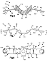
- the rocking contact 80 has a central portion 82.
- the central portion 82 has an open U-shape including a base leg 84 and two side legs 86 and 88.
- the side legs 86 and 88 extend upward and outward from the base leg 84.
- the rocking contact 80 has first and second arms 90 and 92 which extend outward from the central portion 82 of the rocking contact. Because the rocking contact 80 is made as one piece from metal, the first and second arms 90 and 92 of the rocking contact are in electrical contact with each other as well as with the central portion 82 of the rocking contact.
- the first arm 90 of the rocking contact 80 has a relatively short inner portion 94 which extends from the first side leg 86 in a direction parallel to the base leg 84.
- a relatively long outer portion 96 of the first arm 90 extends from the inner portion 94, at a slight angle downward from the inner portion.
- the outer end of the first arm 90 is deformed to form a part-spherical first contact pad at 98.
- a highly conductive metal formed into a sphere may be the contact pad 98.
- the second arm 92 of the rocking contact 80 has a relatively short inner portion 100 which extends from the second side leg 88 in a direction parallel to the base leg 84.
- a relatively long outer portion 102 of the second arm 92 extends from the inner portion 100, at a slight angle downward from the inner portion.
- the material of the second arm 92 is deformed downward to form a part-spherical first contact pad 104 at the outer end of the second arm.
- a highly conductive metal formed into a sphere may be the contact pad 104.
- the plastic body portion 110 of the moving contact assembly is molded around the central portion 82 of the rocking contact 80. Alternatively, the plastic body portion 110 could be bonded to the central portion 82.
- the plastic body 110 has a first surface 112 which has a concave configuration. The first surface 112 is presented upward toward the lever 20. Thus, the first surface 112 on the plastic body 110 is presented toward the outer end surface 40 of the pin 36.
- the metal side leg 86 of the rocking contact 80 is exposed, through the plastic body portion 110, for electrical contact with the pivot stand 60.
- the spring biased pin 36 applies a downward force to urge the moving contact assembly 70 downwardly into engagement with the pivot stand 60.
- the outer end surface 40 on the pin 36 engages the first surface 112 on the plastic body portion 110 of the moving contact assembly 70.
- the metal side leg 86 of the rocking contact 80 engages the metal pivot stand 60 to make electrical contact.
- the pivot stand 60 supports the moving contact assembly 70 for rocking movement in opposite first and second directions, as controlled by the lever 20.
- the lever 20 is initially in the centered or neutral position, as illustrated in Fig. 3.
- the rocker switches 14 and 16 are not actuated and are not providing electrical power to the motor.
- the contact pad 104 of the second arm 92 of the rocking contact 80 engages the ground terminal 54 and as a result the electric motor 11 is not actuated to move the window down.
- the first arm (not shown) of the second rocker switch 16 engages its associated ground terminal and so the motor 11 is not actuated to move the window up.
- the lever 20 can also be pivoted somewhat farther in the same direction to a second actuating position.
- the second actuating position of the lever 20 causes the first arm 90 of the rocking contact 80 to be deformed and applies an outwardly directed force to the contact pad 98.
- the contact pad 98 slides outward over the contact surface 52 on the B+ terminal 50, by the distance marked 120 in Fig. 5A. As this sliding movement occurs, the contact pad 98 and the contact surface 52 are "wiped” to clean them, as illustrated in Figs. 5 and 5A.
- this additional pivoting action takes place every time the rocker switch 14 is actuated.
- the lever 20 is pivoted about seven degrees to make electrical contact.
- An additional eleven degrees of pivotal movement resutls in the wiping action. This is the full range of movement of the lever 20.
- the lever 20 is pivoted in a second direction opposite the first direction, that is, counterclockwise as viewed in Fig. 3.
- the second rocker switch 16 (Fig. 1) is actuated and the motor is operated in an opposite direction of rotation to move the window upward.
- the structure and operation of the second rocker switch 16 are similar to those of the first rocker switch 14 and therefore are not described.
- Each one of the first and second arms 90 and 92 of the rocking contact 80 is selectively bendable to determine the pressure of the engagement between the arm and its associated terminal.
- the first arm 90 can be bent at the intersection between the inner portion 94 and the outer portion 96. If the outer portion 96 is bent farther downward from the inner portion 94, then the pressure of the first contact pad 98 on the B+ terminal 50 is increased. Conversely, if the outer portion 96 is bent farther upward from the inner portion 94, then the pressure of the first contact pad 98 on the B+ terminal 50 is decreased.
- the sliding movement of the outer end surface 40 of the pin 36, along the first surface 112 on the moving contact assembly 70, provides a tactile feel to the person moving the lever 20.
- This tactile feel is controlled by the contour of the surfaces 40 and 112.
- the contour of either or both of these surfaces 40 and 112 can be changed to provide a different tactile feel.
- the contour of the first surface 112 on the plastic body portion 10 of the moving contact assembly 70 can be changed simply by molding the plastic body portion with a different contour. This change can be made without affecting the configuration or operation of the metal portion of the moving contact assembly 70, that is, the rocking contact 80.
- the switch assembly 10 also includes two dome switches 130 and 132 (Fig. 2) for holding the motor 11 actuated in an automatic operation mode.
- the operation of these dome switches 130 and 132 is the same as the operation of the dome switches described in U.S. Patent No. 5,598,918 and is not, therefore, described further herein.
- the invention relates to an electrical switch comprising: first and second spaced contracts; a rocking contact having first and second arms in electrical contact with each other; a support supporting said rocking contact for rocking movement in opposite first and second directions; and a member which pivots to effect rocking movement of said rocking contact in said first and second directions.
Landscapes
- Rotary Switch, Piano Key Switch, And Lever Switch (AREA)
Applications Claiming Priority (2)
| Application Number | Priority Date | Filing Date | Title |
|---|---|---|---|
| US389180 | 1999-09-02 | ||
| US09/389,180 US6175090B1 (en) | 1999-09-02 | 1999-09-02 | Rocker switch |
Publications (3)
| Publication Number | Publication Date |
|---|---|
| EP1081730A2 true EP1081730A2 (de) | 2001-03-07 |
| EP1081730A3 EP1081730A3 (de) | 2003-05-21 |
| EP1081730B1 EP1081730B1 (de) | 2006-03-08 |
Family
ID=23537182
Family Applications (1)
| Application Number | Title | Priority Date | Filing Date |
|---|---|---|---|
| EP00118979A Expired - Lifetime EP1081730B1 (de) | 1999-09-02 | 2000-09-01 | Wippschalter |
Country Status (4)
| Country | Link |
|---|---|
| US (1) | US6175090B1 (de) |
| EP (1) | EP1081730B1 (de) |
| DE (1) | DE60026411T2 (de) |
| ES (1) | ES2259964T3 (de) |
Cited By (6)
| Publication number | Priority date | Publication date | Assignee | Title |
|---|---|---|---|---|
| EP1288985A3 (de) * | 2001-08-30 | 2004-12-15 | Niles Parts Co., Ltd. | Schalter |
| DE10341101A1 (de) * | 2003-09-05 | 2005-04-21 | Trw Automotive Electron & Comp | Kippschalter und Verfahren zur Herstellung eines 2-stufigen Kippschalters |
| EP1526559A1 (de) * | 2003-10-24 | 2005-04-27 | TRW Automotive U.S. LLC | Wippschalter |
| US7083434B1 (en) * | 2005-03-10 | 2006-08-01 | Trw Automotive Us Llc | Electrical apparatus with compliant pins |
| EP2371596A1 (de) * | 2010-03-29 | 2011-10-05 | Delphi Technologies, Inc. | Dachschaltereinheit |
| EP3018682A1 (de) * | 2014-11-10 | 2016-05-11 | Valeo Japan Co., Ltd. | Schaltvorrichtung |
Families Citing this family (20)
| Publication number | Priority date | Publication date | Assignee | Title |
|---|---|---|---|---|
| US6559393B2 (en) * | 2001-03-21 | 2003-05-06 | Sagami Electric Company | Switch having a seesaw type movable contact blade |
| US6384355B1 (en) | 2001-09-04 | 2002-05-07 | Delphi Technologies, Inc. | Parallel guide mechanism for a switch |
| ITMI20012002A1 (it) * | 2001-09-27 | 2003-03-27 | Vimar Spa | Meccanismo di azionamento a compressione mediante tasto basculante diinterruttori commutatori deviatori e simili |
| US7535454B2 (en) | 2001-11-01 | 2009-05-19 | Immersion Corporation | Method and apparatus for providing haptic feedback |
| US6570114B1 (en) | 2001-11-05 | 2003-05-27 | Reliance Controls Corporation | Center contact and rocker arrangement for a single pole double-throw switch |
| US6600122B1 (en) | 2001-11-05 | 2003-07-29 | Reliance Controls Corporation | Centering arrangement for a movable contact member in a rocker-type switch |
| US6596956B1 (en) | 2001-11-05 | 2003-07-22 | Reliance Controls Corporation | SPDT switch with multiple contact arrangement |
| JP3964754B2 (ja) * | 2002-07-30 | 2007-08-22 | アルプス電気株式会社 | スイッチ装置 |
| JP4279648B2 (ja) * | 2003-10-20 | 2009-06-17 | アルプス電気株式会社 | スイッチ装置 |
| US7009128B1 (en) | 2004-01-12 | 2006-03-07 | Reliance Controls Corporation | Side contact rocker-type switch assembly |
| US7439832B1 (en) * | 2004-03-16 | 2008-10-21 | Pass & Seymour, Inc. | Electrical wiring device switch assembly and combination device with circuit protection component |
| US20060107523A1 (en) * | 2004-11-24 | 2006-05-25 | Trw Inc. | Method of making a printed circuit board |
| US7288908B2 (en) * | 2005-07-05 | 2007-10-30 | Trw Automotive U.S. Llc | Switching arrangement |
| US7525054B2 (en) * | 2006-07-03 | 2009-04-28 | Swann Industries Pte Ltd. | Interlock door switch |
| US9582178B2 (en) | 2011-11-07 | 2017-02-28 | Immersion Corporation | Systems and methods for multi-pressure interaction on touch-sensitive surfaces |
| CN102568896A (zh) * | 2011-12-05 | 2012-07-11 | 张家港华捷电子有限公司 | 调速开关 |
| US9443679B2 (en) | 2013-11-08 | 2016-09-13 | Carling Technologies, Inc. | Two-piece rocker assembly |
| CN105428132B (zh) * | 2014-09-22 | 2018-07-03 | 施耐德电气(澳大利亚)有限公司 | 开关结构 |
| EP3218914B1 (de) * | 2014-11-14 | 2025-01-08 | Power Products, LLC | Einpoliger batterieschalter mit verbesserter kontaktkuppel |
| WO2019075288A1 (en) | 2017-10-12 | 2019-04-18 | Flow Control Llc. | FULL ROCKER HOUSING WITH PIEZOELECTRIC VIBRATOR |
Family Cites Families (8)
| Publication number | Priority date | Publication date | Assignee | Title |
|---|---|---|---|---|
| US3294932A (en) * | 1965-05-17 | 1966-12-27 | Western Electric Co | Wiping contact switch |
| GB1308444A (en) | 1969-07-14 | 1973-02-21 | Carr Fastener Co Ltd | Electrical switch |
| US4471181A (en) * | 1982-12-10 | 1984-09-11 | Cooper Industries, Inc. | Electric switch with cleaning action |
| DE8816238U1 (de) | 1988-12-31 | 1989-03-02 | Priesemuth, Wolfgang, 25524 Breitenburg | Tastschalter |
| US5149924A (en) | 1989-05-05 | 1992-09-22 | Priesemuth W | Multiple contact switch arrangement |
| US5833048A (en) | 1995-02-07 | 1998-11-10 | Eaton Corporation | Rocker switch especially for vehicles |
| US5598918A (en) | 1995-05-18 | 1997-02-04 | Trw Inc. | Switch for vehicle power window |
| JPH09134644A (ja) * | 1995-11-10 | 1997-05-20 | Omron Corp | スイッチ装置 |
-
1999
- 1999-09-02 US US09/389,180 patent/US6175090B1/en not_active Expired - Fee Related
-
2000
- 2000-09-01 ES ES00118979T patent/ES2259964T3/es not_active Expired - Lifetime
- 2000-09-01 EP EP00118979A patent/EP1081730B1/de not_active Expired - Lifetime
- 2000-09-01 DE DE60026411T patent/DE60026411T2/de not_active Expired - Fee Related
Cited By (11)
| Publication number | Priority date | Publication date | Assignee | Title |
|---|---|---|---|---|
| EP1288985A3 (de) * | 2001-08-30 | 2004-12-15 | Niles Parts Co., Ltd. | Schalter |
| EP1843372A3 (de) * | 2001-08-30 | 2008-01-23 | Niles Parts Co., Ltd. | Schalter |
| DE10341101A1 (de) * | 2003-09-05 | 2005-04-21 | Trw Automotive Electron & Comp | Kippschalter und Verfahren zur Herstellung eines 2-stufigen Kippschalters |
| US7071435B2 (en) | 2003-09-05 | 2006-07-04 | Trw Automotive Electronics & Components Gmbh & Co. Kg | Toggle switch and method for manufacturing a two-stage toggle switch |
| DE10341101B4 (de) * | 2003-09-05 | 2006-10-12 | Trw Automotive Electronics & Components Gmbh & Co. Kg | Kippschalter |
| CN1312713C (zh) * | 2003-09-05 | 2007-04-25 | Trw车辆电气与零件有限两合公司 | 拨动开关以及制造两级拨动开关的方法 |
| EP1526559A1 (de) * | 2003-10-24 | 2005-04-27 | TRW Automotive U.S. LLC | Wippschalter |
| US7083434B1 (en) * | 2005-03-10 | 2006-08-01 | Trw Automotive Us Llc | Electrical apparatus with compliant pins |
| EP2371596A1 (de) * | 2010-03-29 | 2011-10-05 | Delphi Technologies, Inc. | Dachschaltereinheit |
| EP3018682A1 (de) * | 2014-11-10 | 2016-05-11 | Valeo Japan Co., Ltd. | Schaltvorrichtung |
| US9530587B2 (en) | 2014-11-10 | 2016-12-27 | Valeo Japan Co., Ltd. | Switch device |
Also Published As
| Publication number | Publication date |
|---|---|
| ES2259964T3 (es) | 2006-11-01 |
| DE60026411D1 (de) | 2006-05-04 |
| EP1081730B1 (de) | 2006-03-08 |
| DE60026411T2 (de) | 2006-10-12 |
| US6175090B1 (en) | 2001-01-16 |
| EP1081730A3 (de) | 2003-05-21 |
Similar Documents
| Publication | Publication Date | Title |
|---|---|---|
| US6175090B1 (en) | Rocker switch | |
| JP3108011B2 (ja) | パワーウィンドの運動を制御するための装置 | |
| KR100386353B1 (ko) | 다기능 스위치 | |
| US7944335B2 (en) | Operating element with tilt haptics | |
| US6635832B1 (en) | Electrical switch | |
| US6576855B2 (en) | Rocker switch | |
| US4866221A (en) | Remote power mirror switch assembly | |
| US6998546B1 (en) | Switch assembly for a vehicle | |
| US6580039B2 (en) | Multidirectional switch and operation unit using the same | |
| US5744769A (en) | Electrical switch for use in an automotive vehicle | |
| US6091038A (en) | Electrical switch with sliding terminal contacts | |
| US5023417A (en) | Switch assembly having a rocker switch connected to a remote actuator | |
| US7525052B2 (en) | Multifunction switch assembly for power adjusted vehicle passenger seat | |
| US2756290A (en) | Automotive seat adjusting switch | |
| RU2121185C1 (ru) | Многофункциональный выключатель, преимущественно выключатель для регулирования положения зеркала автомобиля | |
| US4780580A (en) | Switch for motor | |
| US7528335B2 (en) | Light assembly for vehicle interiors | |
| CN120418123A (zh) | 用于机动车的转向柱开关 | |
| EP0689215A1 (de) | Selbstreinigender Schalter mit drehbar gelagertem Kontakt | |
| US5506379A (en) | Direct connect yoke terminal | |
| EP2458608B1 (de) | Elektrischer Schalter | |
| EP0727795A2 (de) | Mehrstufiger Schalter mit Zwangstrennungsmechanismus | |
| EP1678731B1 (de) | Stösselkontaktbaugruppe für einen automobil-steuerhebel | |
| EP0556911B1 (de) | Mechanische Verriegelung für Schütze | |
| US7288908B2 (en) | Switching arrangement |
Legal Events
| Date | Code | Title | Description |
|---|---|---|---|
| PUAI | Public reference made under article 153(3) epc to a published international application that has entered the european phase |
Free format text: ORIGINAL CODE: 0009012 |
|
| AK | Designated contracting states |
Kind code of ref document: A2 Designated state(s): AT BE CH CY DE DK ES FI FR GB GR IE IT LI LU MC NL PT SE |
|
| AX | Request for extension of the european patent |
Free format text: AL;LT;LV;MK;RO;SI |
|
| PUAL | Search report despatched |
Free format text: ORIGINAL CODE: 0009013 |
|
| AK | Designated contracting states |
Designated state(s): AT BE CH CY DE DK ES FI FR GB GR IE IT LI LU MC NL PT SE |
|
| AX | Request for extension of the european patent |
Extension state: AL LT LV MK RO SI |
|
| 17P | Request for examination filed |
Effective date: 20031120 |
|
| AKX | Designation fees paid |
Designated state(s): DE ES GB IT |
|
| RAP1 | Party data changed (applicant data changed or rights of an application transferred) |
Owner name: TRW AUTOMOTIVE U.S. LLC |
|
| 17Q | First examination report despatched |
Effective date: 20040219 |
|
| GRAP | Despatch of communication of intention to grant a patent |
Free format text: ORIGINAL CODE: EPIDOSNIGR1 |
|
| GRAS | Grant fee paid |
Free format text: ORIGINAL CODE: EPIDOSNIGR3 |
|
| GRAA | (expected) grant |
Free format text: ORIGINAL CODE: 0009210 |
|
| AK | Designated contracting states |
Kind code of ref document: B1 Designated state(s): DE ES GB IT |
|
| REG | Reference to a national code |
Ref country code: GB Ref legal event code: FG4D |
|
| REF | Corresponds to: |
Ref document number: 60026411 Country of ref document: DE Date of ref document: 20060504 Kind code of ref document: P |
|
| REG | Reference to a national code |
Ref country code: ES Ref legal event code: FG2A Ref document number: 2259964 Country of ref document: ES Kind code of ref document: T3 |
|
| PLBE | No opposition filed within time limit |
Free format text: ORIGINAL CODE: 0009261 |
|
| STAA | Information on the status of an ep patent application or granted ep patent |
Free format text: STATUS: NO OPPOSITION FILED WITHIN TIME LIMIT |
|
| 26N | No opposition filed |
Effective date: 20061211 |
|
| PGFP | Annual fee paid to national office [announced via postgrant information from national office to epo] |
Ref country code: ES Payment date: 20080908 Year of fee payment: 9 |
|
| PGFP | Annual fee paid to national office [announced via postgrant information from national office to epo] |
Ref country code: IT Payment date: 20080915 Year of fee payment: 9 |
|
| PGFP | Annual fee paid to national office [announced via postgrant information from national office to epo] |
Ref country code: GB Payment date: 20080808 Year of fee payment: 9 |
|
| PGFP | Annual fee paid to national office [announced via postgrant information from national office to epo] |
Ref country code: DE Payment date: 20080930 Year of fee payment: 9 |
|
| GBPC | Gb: european patent ceased through non-payment of renewal fee |
Effective date: 20090901 |
|
| PG25 | Lapsed in a contracting state [announced via postgrant information from national office to epo] |
Ref country code: DE Free format text: LAPSE BECAUSE OF NON-PAYMENT OF DUE FEES Effective date: 20100401 |
|
| PG25 | Lapsed in a contracting state [announced via postgrant information from national office to epo] |
Ref country code: GB Free format text: LAPSE BECAUSE OF NON-PAYMENT OF DUE FEES Effective date: 20090901 |
|
| PG25 | Lapsed in a contracting state [announced via postgrant information from national office to epo] |
Ref country code: IT Free format text: LAPSE BECAUSE OF NON-PAYMENT OF DUE FEES Effective date: 20090901 |
|
| REG | Reference to a national code |
Ref country code: ES Ref legal event code: FD2A Effective date: 20110714 |
|
| PG25 | Lapsed in a contracting state [announced via postgrant information from national office to epo] |
Ref country code: ES Free format text: LAPSE BECAUSE OF NON-PAYMENT OF DUE FEES Effective date: 20110704 |
|
| PG25 | Lapsed in a contracting state [announced via postgrant information from national office to epo] |
Ref country code: ES Free format text: LAPSE BECAUSE OF NON-PAYMENT OF DUE FEES Effective date: 20090902 |