EP2371596A1 - Dachschaltereinheit - Google Patents
Dachschaltereinheit Download PDFInfo
- Publication number
- EP2371596A1 EP2371596A1 EP10158120A EP10158120A EP2371596A1 EP 2371596 A1 EP2371596 A1 EP 2371596A1 EP 10158120 A EP10158120 A EP 10158120A EP 10158120 A EP10158120 A EP 10158120A EP 2371596 A1 EP2371596 A1 EP 2371596A1
- Authority
- EP
- European Patent Office
- Prior art keywords
- slider
- actuating member
- switch assembly
- housing
- counter
- Prior art date
- Legal status (The legal status is an assumption and is not a legal conclusion. Google has not performed a legal analysis and makes no representation as to the accuracy of the status listed.)
- Granted
Links
Images
Classifications
-
- H—ELECTRICITY
- H01—ELECTRIC ELEMENTS
- H01H—ELECTRIC SWITCHES; RELAYS; SELECTORS; EMERGENCY PROTECTIVE DEVICES
- H01H25/00—Switches with compound movement of handle or other operating part
- H01H25/006—Switches with compound movement of handle or other operating part having an operating member slidable in a plane in one direction and pivotable around an axis located in the sliding plane perpendicular to the sliding direction
-
- B—PERFORMING OPERATIONS; TRANSPORTING
- B60—VEHICLES IN GENERAL
- B60J—WINDOWS, WINDSCREENS, NON-FIXED ROOFS, DOORS, OR SIMILAR DEVICES FOR VEHICLES; REMOVABLE EXTERNAL PROTECTIVE COVERINGS SPECIALLY ADAPTED FOR VEHICLES
- B60J7/00—Non-fixed roofs; Roofs with movable panels, e.g. rotary sunroofs
- B60J7/02—Non-fixed roofs; Roofs with movable panels, e.g. rotary sunroofs of sliding type, e.g. comprising guide shoes
- B60J7/04—Non-fixed roofs; Roofs with movable panels, e.g. rotary sunroofs of sliding type, e.g. comprising guide shoes with rigid plate-like element or elements, e.g. open roofs with harmonica-type folding rigid panels
- B60J7/057—Driving or actuating arrangements e.g. manually operated levers or knobs
- B60J7/0573—Driving or actuating arrangements e.g. manually operated levers or knobs power driven arrangements, e.g. electrical
-
- H—ELECTRICITY
- H01—ELECTRIC ELEMENTS
- H01H—ELECTRIC SWITCHES; RELAYS; SELECTORS; EMERGENCY PROTECTIVE DEVICES
- H01H21/00—Switches operated by an operating part in the form of a pivotable member acted upon directly by a solid body, e.g. by a hand
- H01H21/02—Details
- H01H21/18—Movable parts; Contacts mounted thereon
- H01H21/22—Operating parts, e.g. handle
- H01H2021/225—Operating parts, e.g. handle with push-pull operation, e.g. which can be pivoted in both directions by pushing or pulling on the same extremity of the operating member
-
- H—ELECTRICITY
- H01—ELECTRIC ELEMENTS
- H01H—ELECTRIC SWITCHES; RELAYS; SELECTORS; EMERGENCY PROTECTIVE DEVICES
- H01H23/00—Tumbler or rocker switches, i.e. switches characterised by being operated by rocking an operating member in the form of a rocker button
- H01H23/006—Tumbler or rocker switches, i.e. switches characterised by being operated by rocking an operating member in the form of a rocker button adapted for connection with printed circuit boards
-
- H—ELECTRICITY
- H01—ELECTRIC ELEMENTS
- H01H—ELECTRIC SWITCHES; RELAYS; SELECTORS; EMERGENCY PROTECTIVE DEVICES
- H01H2300/00—Orthogonal indexing scheme relating to electric switches, relays, selectors or emergency protective devices covered by H01H
- H01H2300/006—Application power roofs
Definitions
- the present invention relates to an electrical switch assembly for sliding-rising-roofs of motor vehicles, the switch assembly being provided with a counter-force device generating a counter force when actuating the switch button.
- Switch assemblies of the aforementioned type interrupt and complete electrical circuits by moving electrical switches disposed in the housing of the switch assembly to connect fixed electrical switching devices. It is thus possible for a user to apply an auxiliary force to an actuating element to switch on and off functions associated with different electrical circuits. Often such switch assemblies switch on and off the sliding and rising roof functions of a sliding-rising-roof of a motor vehicle.
- DE 39 31 722 C2 discloses a switch assembly having a housing which receives movable electrical switching contacts.
- the housing has a transverse axis and a longitudinal axis.
- An actuating element is mounted on the housing.
- Each of two axle journals associated with the actuating element engage a longitudinally elongated hole provided in opposite walls of the housing in parallel with the longitudinal axis.
- the two axle journals are rotatable and longitudinally displaceable within the elongated holes such that the actuating element is pivotable about the transverse axis and longitudinally movable along the longitudinal axis to move between switching positions.
- the actuating element includes two guide cams each spaced apart from an axle journal in parallel with the longitudinal axis.
- the guide cams each engage a cross-shaped connecting member provided on the opposite walls of the housing to enable the actuating element to be pivotable and longitudinally movable.
- the actuating element can therefore be moved to switching positions by sliding and pivoting movements which correspond to the movements of a sliding-rising-roof of a motor vehicle.
- the actuating element includes switching pieces which transmit the actuating element movements to the movable switching contacts to complete electrical circuits and enable switching functions associated with the switching positions. Furthermore, the switch assembly includes a plurality of compression spring-loaded control devices which ensure that the actuating element remains in a starting position and automatically returns from a switching position to the starting position.
- DE 34 15 997 C2 discloses a switch assembly wherein movements of the actuating element correspond to the movements of a sliding-rising-roof of a motor vehicle.
- the actuating element also includes two axle journals which are rotatable and longitudinally movable within elongated holes provided in opposite walls of the housing.
- the actuating element further includes two guide cams which pivotable and longitudinally displaceable engage a respective cross-shaped connecting member of the housing.
- EP0778980 and US6046414 disclose other examples of this type of switch assembly.
- a problems associated with the existing solutions of the switch assembly are, primarily that the assemblies include a considerable number of individual parts complicated to assemble, secondly the packaging required for the assembly is large while the available space in modem cars diminishes and thirdly, because of the internal arrangement of the components, the return force provided to the user manipulating the actuating element varies according to the direction where the actuating element is moved.
- a switch assembly for a sliding-rising-roof of a motor vehicle which maintains a high degree of functionality, which has a compact design, and which consists of exceptionally few individual parts which are convenient to assemble.
- the present invention provides a switch assembly according to the preamble of claim 1.
- the switch assembly as per the invention comprises a housing, an actuating member mounted on the housing and a plurality of electrical switching members.
- the actuating member is able, with regards to the housing, to translate frontward and backward along a longitudinal axis and to pivot upward and downward about a transverse axis thus cooperating with the electrical switching members to control the roof displacements.
- the switch assembly further comprises two sliders solely able to translate along the longitudinal axis.
- the sliders are driven by the actuating member and are cooperating with the switching members in order to generate a switching function controlling the roof displacements.
- the switching function is derived from the positions of the switching members actuated by both sliders.
- the translation of the actuating member drives both sliders along the same longitudinal direction so that there is no relative displacement between the sliders and, the pivoting of the actuating member drives the second slider in the longitudinal direction while the first slider standstill so there is a relative displacement between the sliders.
- the first slider is mounted inside the housing and is longitudinally guided by the housing and, the second slider is mounted into the first slider and is longitudinally guided by the first slider.
- the switch assembly further comprises at least one counterforce device providing a counter-force to the user moving the actuating member, the counter-force device comprising an elastically deformable portion providing a force feedback when deformed by the displacements of the slider. In absence of action from a user the actuating member standstill in a neutral position. The neutral position is determined by the counter-force device.
- the switch assembly comprises four counter-force devices each one being associated with a distinct displacement of the actuating member.
- the housing has substantially the shape of a parallelepiped rectangle provided with a front transversal wall and a back transversal wall longitudinally apart from each other.
- the first slider is mounted inside the housing between the front and back walls of the housing and is itself provided with a front transversal wall and a back transversal wall longitudinally apart from each other.
- the second slider is mounted onto the first slider between the front and back walls of the first slider and is itself provided with a front transversal wall and a back transversal wall longitudinally apart from each other.
- the first counter force device is mounted between the front wall of the housing and the front wall of the first slider and provides counter force to the frontward translation of the actuating member.
- the second counter force device is mounted between the back wall of the housing and the back wall of the first slider and provides counter force to the backward translation of the actuating member.
- the third counter force device is mounted between the front wall of the first slider and the front wall of the second slider and provides counter force to the downward, respectively upward, pivoting of the actuating member.
- the fourth counter force device is mounted between the back wall of the first slider and the back wall of the second slider and provides counter force to the upward, respectively downward, pivoting of the actuating member.
- All four counter-force devices are identical and all four counter-force devices are substantially operating in a single plane that is parallel to the plane of the longitudinal and of the transverse axis.
- the switch assembly is further provided with a guiding device for the actuating member forbidding any combination of translation and pivoting of the actuating member.
- the switch assembly as per the present invention provides the advantages that the user receives identical force feedback whatever the directions he actuates the switch.
- the guiding and actuating of the components is designed to be simple therefore requiring manufacturing tolerances easier to achieve.
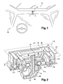
- Figure 1 sketches the environment and usual location of a switch 14 for operating a sliding-rising-roof 12.
- the switch assembly 14 is placed above the driver.
- the switch assembly 14 is fixed on a printed circuit board 18 substantially horizontally embedded in the fixed portion of the roof of the vehicle 10.
- the switch assembly 14 is spotted in a tridimensional axial system comprising a longitudinal axis X substantially horizontal and defining a frontward direction and a backward direction, a transverse axis Y substantially horizontal and orthogonal to the longitudinal axis X and the vertical axis Z defining an upward direction and a downward direction.
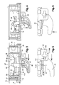
- FIGS 2 to 6 detail a preferred embodiment of the switch assembly 14 which comprises a housing 20 shaped as a parallelepiped rectangle closed on five sides being four lateral planar vertical walls 22, 24, 26, 28 and a horizontal bottom-cover 30.
- the sixth side which is open, is against the printed circuit board 18 that is substantially horizontal.
- the four walls are a front transversal wall 22 and a back transversal wall 24 distant from each other along the longitudinal axis X, a right longitudinal wall 26 and a left longitudinal wall 28 distant from each other along the transverse axis Y.
- the bottom-cover 30 is adjusted and attached to the housing 20. Once on the printed circuit board 18, the housing 20 is closed on all six sides and defines an inside volume 32.
- the bottom-cover 30 is provided with a substantially rectangular opening 34 centrally placed in the bottom-cover 30.
- Other shapes of the opening 34 are of course possible.
- the switch assembly 14 further comprises an actuating member 40 extending from an upper end 42 to a lower end 44.
- the actuating member 40 extends through the rectangular opening 34 of the bottom-cover 30, the upper end 42 being inside the housing 20 close to the printed circuit board 18, and the lower end 44 being outside the housing 20, accessible to a user.
- a button-cap 46 is adjusted and fixed onto the lower end 44 providing to the user an ergonomic interface to move the actuating member 40.
- the actuating member 40 may be hollow as represented on Figure 2 or plain.
- a light guide 48 is placed in the actuating member 40 and the button-cap 46 is holed so that a light emitted by a light source (not represented) placed on the printed circuit board 18 is directed downward illuminating the button-cap 46 thus making it more visible to the user.
- a first slider 52 that comprises a rectangular floor 54, a front transversal wall 56 and a back transversal wall 58.
- the rectangular floor 54 is shorter in length than the housing 20 and fitted in width to the housing 20. At both extremities of the length of the rectangular floor 54 upwardly extend the front wall 56 and the back wall 58.
- the front wall 56 of the first slider 52 faces the front wall 22 of the housing 20 and, the back wall 58 of the first slider 52 faces the back wall 24 of the housing 20.
- a guiding mean (not represented) of the first slider 52 relative to the housing 20 forbids any other displacement than a longitudinal translation along the longitudinal axis X.
- the rectangular floor 54 of the first slider 52 is provided with an opening 68 through which extends the actuating member 40.
- the actuating member 40 is pivotally mounted about a transverse pivot axis AP that is parallel to the transverse axis Y.
- a pivoting mean 70 comprises two transversally aligned pivoting holes 72, 74 operated in two downward extensions 76, 78 of the first slider 52.
- the two extensions 76, 78 extend through the rectangular opening 34 operated in the housing 20 and, between them, extends the actuating member 40.
- Two male pins 80, 82 transversally extending from the actuating member 40 cooperate with the pivoting holes 72, 74 thus forming the pivot axis AP about which pivots the actuating member 40 relative to the first slider 52.
- the opening 68 is sufficient in dimension so the rectangular floor 54 does not interfere with the actuating member 40.
- the opening 68 may have a downwardly oriented V-shape, the angle of the V matching the pivoting angle of the actuating member 40.
- a second slider 90 shaped as a parallelepiped rectangle shorter in length than the first slider 52 and fitted in width to the first slider 52, the four vertically extending sides of the parallelepiped rectangle being a left and a right longitudinal walls and a front 92 and a back 94 transversal walls.
- the front wall 92 and the back wall 94 of the second slider 90 respectively face the front wall 56 and a back wall 58 of the first slider 52.
- the second slider 90 is able to translate inside the first slider 52 along the longitudinal axis X.
- a guiding mean (not represented) of the second slider 90 relative to the first slider 52 forbids any other displacement than a longitudinal translation of the second slider 90.
- the second slider 90 is further provided with a centrally placed vertical opening 96 which cooperates with the upper end 42 of the actuating member 40 creating a sliding-pivot knuckle 98 ( Figures 3 and 4 ).
- a sliding-pivot knuckle 98 is easily created with, for instance, a cylindrical vertical opening and a spherically shaped up-extremity.
- the actuating member 40 can move relative to the housing 20 and is guided in its movements by a guiding mean 100 comprising a guiding path 102 and a guiding pin 104 that follows the path 102.
- the guiding path 102 is operated in a downward extension 106 of a longitudinal wall 26, 28 of the housing 20.
- the guiding path 102 has the shape of a cross straightly extending along the longitudinal axis X and curvedly extending substantially along the vertical axis Z, the curve being centered on the pivot axis AP when the guiding pin 104 is in the middle of the cross-shaped guiding path 102.
- the center of the cross shaped guiding path 102 defines a neutral position PN for the switch assembly 14.
- first deformable plastic dome 110 is placed between the front wall 22 of the housing 20 and the front wall 56 of the first slider 52.
- a second deformable plastic dome 112 is placed between the back wall 24 of the housing 20 and the back wall 58 of the first slider 52.
- a third deformable plastic dome 114 is placed between the front wall 22 of the first slider 52 and the front wall 92 of the second slider 90.
- a fourth deformable plastic dome 116 is placed between the back wall 24 of the first slider 52 and the back wall 94 of the second slider 90.
- Each deformable plastic dome generates a force when it is compressed, thus providing a counterforce to the displacement of a slider 52, 90. The counter forces are felt by the user manipulating the actuating member 40.
- the deformable plastic dome are identical and are placed substantially in a common plane that is horizontal. Such an arrangement provided to the user counter forces with equal intensity.
- the above described embodiment of the switch assembly 14 can be manipulated so its actuating member 40 can either be displaced in one of the four directions, front back up or down, or can be left untouched.
- the sliders 52, 90 can consequently be in five different operating mode here after detailed.
- Operating mode 1 The frontward translation of the actuating member 40 ( figure 2 , 3 and 5 ) frontwardly translates both the first slider 52 and the second slider 90 so that the front wall 56 of the first slider 52 gets closer to the front wall 22 of the housing 20 while the second slider 90 remains centered in the first slider 52. Only the first dome 110 is compressed generating a backwardly oriented counterforce F1 to the frontward translation of the actuating member 40.
- Operating mode 2 The backward translation of the actuating member 40 backwardly translates both the first slider 52 and the second slider 90 so that the back wall 58 of the first slider 52 gets closer to the back wall 24 of the housing 20 while the second slider 90 remains centered relative to the first slider 52. Only the second dome 112 is compressed generating a frontwardly oriented counterforce F2 to the backward translation of the actuating member 40.
- Operating mode 3 The downward pivoting of the actuating member 40 ( Figure 4 ) frontwardly translates the second slider 90 while the first slider 52 standstill centered relative to the housing 20.
- the front wall 92 of the second slider 90 gets closer to the front wall 22 of the first slider 52.
- Only the third dome 114 is compressed generating a backwardly oriented counterforce F3 to the downward pivoting of the actuating member 40.
- Operating mode 4 The upward pivoting of the actuating member 40 backwardly translates the second slider 90 while the first slider standstill centered relative to the housing 20.
- the back wall 94 of the second slider 90 gets closer to the back wall 24 of the first slider 52.
- Only the fourth dome 116 is compressed generating a frontwardly oriented counterforce F4 to the upward pivoting of the actuating member 40.
- the deformable plastic domes 110, 112, 114, 116 act as compression spring.
- An alternative to the plastic dome is any kind of elastically deformable feature providing a return force, such as a flexible blade spring or a coil spring,
- the upward pivoting of the actuating member 40 could generate a frontward translation of the second slider 90 and reversely a downward pivoting would generate a backward translation.
- first switching member Upwardly extending from the first slider 52 is a first switching member (not represented) that cooperates with a matching element placed on the printed circuit board 18 in order to generate first switching information.
- a second switching member (not represented) that cooperates with a matching element placed on the circuit board 18 in order to generate second switching information.
- the electrical switching members cooperating with their matching element can be of any type such as contact blades, Hall Effect sensors, light barrier or other.
Landscapes
- Engineering & Computer Science (AREA)
- Mechanical Engineering (AREA)
- Tumbler Switches (AREA)
Priority Applications (2)
| Application Number | Priority Date | Filing Date | Title |
|---|---|---|---|
| EP10158120A EP2371596B1 (de) | 2010-03-29 | 2010-03-29 | Dachschaltereinheit |
| US13/042,522 US20110233038A1 (en) | 2010-03-29 | 2011-03-08 | Roof switch assembly |
Applications Claiming Priority (1)
| Application Number | Priority Date | Filing Date | Title |
|---|---|---|---|
| EP10158120A EP2371596B1 (de) | 2010-03-29 | 2010-03-29 | Dachschaltereinheit |
Publications (2)
| Publication Number | Publication Date |
|---|---|
| EP2371596A1 true EP2371596A1 (de) | 2011-10-05 |
| EP2371596B1 EP2371596B1 (de) | 2012-12-05 |
Family
ID=42200859
Family Applications (1)
| Application Number | Title | Priority Date | Filing Date |
|---|---|---|---|
| EP10158120A Not-in-force EP2371596B1 (de) | 2010-03-29 | 2010-03-29 | Dachschaltereinheit |
Country Status (2)
| Country | Link |
|---|---|
| US (1) | US20110233038A1 (de) |
| EP (1) | EP2371596B1 (de) |
Families Citing this family (2)
| Publication number | Priority date | Publication date | Assignee | Title |
|---|---|---|---|---|
| WO2017172630A1 (en) | 2016-03-30 | 2017-10-05 | Shanghai Yanfeng Jinqiao Automotive Trim Systems Co. Ltd | Mechanism for console assembly |
| DE102020130470B3 (de) | 2020-11-18 | 2022-03-17 | Valeo Schalter Und Sensoren Gmbh | Wipptasterbaugruppe |
Citations (9)
| Publication number | Priority date | Publication date | Assignee | Title |
|---|---|---|---|---|
| DE3415997C2 (de) | 1984-04-28 | 1987-07-09 | Daimler-Benz Ag, 7000 Stuttgart, De | |
| DE3931722C1 (en) | 1989-09-22 | 1990-12-20 | Trw Messmer Gmbh & Co Kg, 7760 Radolfzell, De | Vehicle sunroof switch and push mechanism - has pivot-mounted actuator button, and switch actuator pins in sliding block |
| US5412164A (en) * | 1993-12-03 | 1995-05-02 | General Motors Corporation | Dual action switch assembly with sequentially actuated membrane switches including a reciprocating circuit board |
| EP0778980A1 (de) | 1994-09-01 | 1997-06-18 | EATON CONTROLS GmbH & Co. KG | Hub-schiebe-schalter |
| US6046414A (en) | 1997-06-19 | 2000-04-04 | Leopold Kostal Gmbh & Co. Kg | Switch assembly |
| EP1081730A2 (de) * | 1999-09-02 | 2001-03-07 | Trw Inc. | Wippschalter |
| EP1526559A1 (de) * | 2003-10-24 | 2005-04-27 | TRW Automotive U.S. LLC | Wippschalter |
| US20050219954A1 (en) * | 2004-03-30 | 2005-10-06 | Tsuyoshi Matsui | Composite switch, and electronic equipment and electronic timepiece which possess composite switch |
| DE102007056155B3 (de) * | 2007-11-21 | 2009-06-18 | Sidler Automotive Gmbh & Co. Kg | Hub-Schiebe-Schalter |
Family Cites Families (3)
| Publication number | Priority date | Publication date | Assignee | Title |
|---|---|---|---|---|
| DE19912086A1 (de) * | 1999-03-18 | 2000-09-21 | Eaton Corp | Hub-Schiebe-Schalter |
| CN100384388C (zh) * | 2002-05-30 | 2008-04-30 | 丘奇和德怀特有限公司 | 电动牙刷及包含电动牙刷的包装盒 |
| DE102007051466A1 (de) * | 2007-10-27 | 2009-04-30 | Rafi Gmbh & Co. Kg | Schaltvorrichtung |
-
2010
- 2010-03-29 EP EP10158120A patent/EP2371596B1/de not_active Not-in-force
-
2011
- 2011-03-08 US US13/042,522 patent/US20110233038A1/en not_active Abandoned
Patent Citations (9)
| Publication number | Priority date | Publication date | Assignee | Title |
|---|---|---|---|---|
| DE3415997C2 (de) | 1984-04-28 | 1987-07-09 | Daimler-Benz Ag, 7000 Stuttgart, De | |
| DE3931722C1 (en) | 1989-09-22 | 1990-12-20 | Trw Messmer Gmbh & Co Kg, 7760 Radolfzell, De | Vehicle sunroof switch and push mechanism - has pivot-mounted actuator button, and switch actuator pins in sliding block |
| US5412164A (en) * | 1993-12-03 | 1995-05-02 | General Motors Corporation | Dual action switch assembly with sequentially actuated membrane switches including a reciprocating circuit board |
| EP0778980A1 (de) | 1994-09-01 | 1997-06-18 | EATON CONTROLS GmbH & Co. KG | Hub-schiebe-schalter |
| US6046414A (en) | 1997-06-19 | 2000-04-04 | Leopold Kostal Gmbh & Co. Kg | Switch assembly |
| EP1081730A2 (de) * | 1999-09-02 | 2001-03-07 | Trw Inc. | Wippschalter |
| EP1526559A1 (de) * | 2003-10-24 | 2005-04-27 | TRW Automotive U.S. LLC | Wippschalter |
| US20050219954A1 (en) * | 2004-03-30 | 2005-10-06 | Tsuyoshi Matsui | Composite switch, and electronic equipment and electronic timepiece which possess composite switch |
| DE102007056155B3 (de) * | 2007-11-21 | 2009-06-18 | Sidler Automotive Gmbh & Co. Kg | Hub-Schiebe-Schalter |
Also Published As
| Publication number | Publication date |
|---|---|
| US20110233038A1 (en) | 2011-09-29 |
| EP2371596B1 (de) | 2012-12-05 |
Similar Documents
| Publication | Publication Date | Title |
|---|---|---|
| JP5813725B2 (ja) | スイッチ装置 | |
| US5721405A (en) | Tactile feedback mechanism for a multidirectional switch | |
| CN101527207B (zh) | 电动工具用开关 | |
| US7238905B2 (en) | Single button six-way sunroof switch | |
| US20230420200A1 (en) | Module for Generating Opening Signals | |
| US8598475B2 (en) | Roof switch assembly | |
| EP2371596B1 (de) | Dachschaltereinheit | |
| CN214588559U (zh) | 开关组件、汽车信息娱乐系统和车辆 | |
| KR101133856B1 (ko) | 차량용 스위치 장치 | |
| KR20190135030A (ko) | 스위치 | |
| US9324516B2 (en) | Click module and operation switch | |
| EP3358590A1 (de) | Kippschaltervorrichtung | |
| KR200471416Y1 (ko) | 차량용 다방향 스위치 장치 | |
| US7528335B2 (en) | Light assembly for vehicle interiors | |
| KR102854191B1 (ko) | 차량용 스위치 장치 | |
| KR200459979Y1 (ko) | 패들 스위치 유니트 | |
| KR102726879B1 (ko) | 차량용 스위치 장치 | |
| KR102506453B1 (ko) | 차량용 멀티 오퍼레이팅 스위치 유닛 | |
| KR200461776Y1 (ko) | 시트 워머 스위치 장치 | |
| EP4473547B1 (de) | Elektrischer schalter | |
| EP3404684B1 (de) | Anordnung mit einer schaltervorrichtung und gehäuse | |
| JP2006269286A (ja) | 押しボタンスイッチ | |
| KR101155265B1 (ko) | 다방향 스위치 장치 | |
| JP2006269287A (ja) | 押しボタンスイッチ | |
| KR20190116814A (ko) | 차량용 레버 |
Legal Events
| Date | Code | Title | Description |
|---|---|---|---|
| PUAI | Public reference made under article 153(3) epc to a published international application that has entered the european phase |
Free format text: ORIGINAL CODE: 0009012 |
|
| AK | Designated contracting states |
Kind code of ref document: A1 Designated state(s): AT BE BG CH CY CZ DE DK EE ES FI FR GB GR HR HU IE IS IT LI LT LU LV MC MK MT NL NO PL PT RO SE SI SK SM TR |
|
| AX | Request for extension of the european patent |
Extension state: AL BA ME RS |
|
| 17P | Request for examination filed |
Effective date: 20120405 |
|
| RIC1 | Information provided on ipc code assigned before grant |
Ipc: B60J 7/057 20060101AFI20120503BHEP Ipc: H01H 23/00 20060101ALI20120503BHEP |
|
| GRAP | Despatch of communication of intention to grant a patent |
Free format text: ORIGINAL CODE: EPIDOSNIGR1 |
|
| GRAS | Grant fee paid |
Free format text: ORIGINAL CODE: EPIDOSNIGR3 |
|
| GRAA | (expected) grant |
Free format text: ORIGINAL CODE: 0009210 |
|
| AK | Designated contracting states |
Kind code of ref document: B1 Designated state(s): AT BE BG CH CY CZ DE DK EE ES FI FR GB GR HR HU IE IS IT LI LT LU LV MC MK MT NL NO PL PT RO SE SI SK SM TR |
|
| REG | Reference to a national code |
Ref country code: GB Ref legal event code: FG4D |
|
| REG | Reference to a national code |
Ref country code: CH Ref legal event code: EP |
|
| REG | Reference to a national code |
Ref country code: AT Ref legal event code: REF Ref document number: 587071 Country of ref document: AT Kind code of ref document: T Effective date: 20121215 |
|
| REG | Reference to a national code |
Ref country code: IE Ref legal event code: FG4D |
|
| REG | Reference to a national code |
Ref country code: DE Ref legal event code: R096 Ref document number: 602010003906 Country of ref document: DE Effective date: 20130131 |
|
| REG | Reference to a national code |
Ref country code: AT Ref legal event code: MK05 Ref document number: 587071 Country of ref document: AT Kind code of ref document: T Effective date: 20121205 |
|
| PG25 | Lapsed in a contracting state [announced via postgrant information from national office to epo] |
Ref country code: LT Free format text: LAPSE BECAUSE OF FAILURE TO SUBMIT A TRANSLATION OF THE DESCRIPTION OR TO PAY THE FEE WITHIN THE PRESCRIBED TIME-LIMIT Effective date: 20121205 Ref country code: SE Free format text: LAPSE BECAUSE OF FAILURE TO SUBMIT A TRANSLATION OF THE DESCRIPTION OR TO PAY THE FEE WITHIN THE PRESCRIBED TIME-LIMIT Effective date: 20121205 Ref country code: FI Free format text: LAPSE BECAUSE OF FAILURE TO SUBMIT A TRANSLATION OF THE DESCRIPTION OR TO PAY THE FEE WITHIN THE PRESCRIBED TIME-LIMIT Effective date: 20121205 Ref country code: NO Free format text: LAPSE BECAUSE OF FAILURE TO SUBMIT A TRANSLATION OF THE DESCRIPTION OR TO PAY THE FEE WITHIN THE PRESCRIBED TIME-LIMIT Effective date: 20130305 Ref country code: ES Free format text: LAPSE BECAUSE OF FAILURE TO SUBMIT A TRANSLATION OF THE DESCRIPTION OR TO PAY THE FEE WITHIN THE PRESCRIBED TIME-LIMIT Effective date: 20130316 |
|
| REG | Reference to a national code |
Ref country code: NL Ref legal event code: VDEP Effective date: 20121205 |
|
| REG | Reference to a national code |
Ref country code: LT Ref legal event code: MG4D |
|
| PG25 | Lapsed in a contracting state [announced via postgrant information from national office to epo] |
Ref country code: SI Free format text: LAPSE BECAUSE OF FAILURE TO SUBMIT A TRANSLATION OF THE DESCRIPTION OR TO PAY THE FEE WITHIN THE PRESCRIBED TIME-LIMIT Effective date: 20121205 Ref country code: LV Free format text: LAPSE BECAUSE OF FAILURE TO SUBMIT A TRANSLATION OF THE DESCRIPTION OR TO PAY THE FEE WITHIN THE PRESCRIBED TIME-LIMIT Effective date: 20121205 Ref country code: PL Free format text: LAPSE BECAUSE OF FAILURE TO SUBMIT A TRANSLATION OF THE DESCRIPTION OR TO PAY THE FEE WITHIN THE PRESCRIBED TIME-LIMIT Effective date: 20121205 Ref country code: GR Free format text: LAPSE BECAUSE OF FAILURE TO SUBMIT A TRANSLATION OF THE DESCRIPTION OR TO PAY THE FEE WITHIN THE PRESCRIBED TIME-LIMIT Effective date: 20130306 |
|
| PG25 | Lapsed in a contracting state [announced via postgrant information from national office to epo] |
Ref country code: AT Free format text: LAPSE BECAUSE OF FAILURE TO SUBMIT A TRANSLATION OF THE DESCRIPTION OR TO PAY THE FEE WITHIN THE PRESCRIBED TIME-LIMIT Effective date: 20121205 |
|
| PG25 | Lapsed in a contracting state [announced via postgrant information from national office to epo] |
Ref country code: CZ Free format text: LAPSE BECAUSE OF FAILURE TO SUBMIT A TRANSLATION OF THE DESCRIPTION OR TO PAY THE FEE WITHIN THE PRESCRIBED TIME-LIMIT Effective date: 20121205 Ref country code: IS Free format text: LAPSE BECAUSE OF FAILURE TO SUBMIT A TRANSLATION OF THE DESCRIPTION OR TO PAY THE FEE WITHIN THE PRESCRIBED TIME-LIMIT Effective date: 20130405 Ref country code: EE Free format text: LAPSE BECAUSE OF FAILURE TO SUBMIT A TRANSLATION OF THE DESCRIPTION OR TO PAY THE FEE WITHIN THE PRESCRIBED TIME-LIMIT Effective date: 20121205 Ref country code: BE Free format text: LAPSE BECAUSE OF FAILURE TO SUBMIT A TRANSLATION OF THE DESCRIPTION OR TO PAY THE FEE WITHIN THE PRESCRIBED TIME-LIMIT Effective date: 20121205 Ref country code: SK Free format text: LAPSE BECAUSE OF FAILURE TO SUBMIT A TRANSLATION OF THE DESCRIPTION OR TO PAY THE FEE WITHIN THE PRESCRIBED TIME-LIMIT Effective date: 20121205 Ref country code: BG Free format text: LAPSE BECAUSE OF FAILURE TO SUBMIT A TRANSLATION OF THE DESCRIPTION OR TO PAY THE FEE WITHIN THE PRESCRIBED TIME-LIMIT Effective date: 20130305 |
|
| PG25 | Lapsed in a contracting state [announced via postgrant information from national office to epo] |
Ref country code: RO Free format text: LAPSE BECAUSE OF FAILURE TO SUBMIT A TRANSLATION OF THE DESCRIPTION OR TO PAY THE FEE WITHIN THE PRESCRIBED TIME-LIMIT Effective date: 20121205 Ref country code: NL Free format text: LAPSE BECAUSE OF FAILURE TO SUBMIT A TRANSLATION OF THE DESCRIPTION OR TO PAY THE FEE WITHIN THE PRESCRIBED TIME-LIMIT Effective date: 20121205 Ref country code: PT Free format text: LAPSE BECAUSE OF FAILURE TO SUBMIT A TRANSLATION OF THE DESCRIPTION OR TO PAY THE FEE WITHIN THE PRESCRIBED TIME-LIMIT Effective date: 20130405 |
|
| PLBE | No opposition filed within time limit |
Free format text: ORIGINAL CODE: 0009261 |
|
| STAA | Information on the status of an ep patent application or granted ep patent |
Free format text: STATUS: NO OPPOSITION FILED WITHIN TIME LIMIT |
|
| PG25 | Lapsed in a contracting state [announced via postgrant information from national office to epo] |
Ref country code: MC Free format text: LAPSE BECAUSE OF NON-PAYMENT OF DUE FEES Effective date: 20130331 Ref country code: DK Free format text: LAPSE BECAUSE OF FAILURE TO SUBMIT A TRANSLATION OF THE DESCRIPTION OR TO PAY THE FEE WITHIN THE PRESCRIBED TIME-LIMIT Effective date: 20121205 |
|
| 26N | No opposition filed |
Effective date: 20130906 |
|
| PG25 | Lapsed in a contracting state [announced via postgrant information from national office to epo] |
Ref country code: CY Free format text: LAPSE BECAUSE OF FAILURE TO SUBMIT A TRANSLATION OF THE DESCRIPTION OR TO PAY THE FEE WITHIN THE PRESCRIBED TIME-LIMIT Effective date: 20121205 |
|
| PG25 | Lapsed in a contracting state [announced via postgrant information from national office to epo] |
Ref country code: IT Free format text: LAPSE BECAUSE OF FAILURE TO SUBMIT A TRANSLATION OF THE DESCRIPTION OR TO PAY THE FEE WITHIN THE PRESCRIBED TIME-LIMIT Effective date: 20121205 |
|
| REG | Reference to a national code |
Ref country code: IE Ref legal event code: MM4A |
|
| REG | Reference to a national code |
Ref country code: DE Ref legal event code: R097 Ref document number: 602010003906 Country of ref document: DE Effective date: 20130906 |
|
| PG25 | Lapsed in a contracting state [announced via postgrant information from national office to epo] |
Ref country code: HR Free format text: LAPSE BECAUSE OF FAILURE TO SUBMIT A TRANSLATION OF THE DESCRIPTION OR TO PAY THE FEE WITHIN THE PRESCRIBED TIME-LIMIT Effective date: 20130731 Ref country code: IE Free format text: LAPSE BECAUSE OF NON-PAYMENT OF DUE FEES Effective date: 20130329 |
|
| PG25 | Lapsed in a contracting state [announced via postgrant information from national office to epo] |
Ref country code: MT Free format text: LAPSE BECAUSE OF FAILURE TO SUBMIT A TRANSLATION OF THE DESCRIPTION OR TO PAY THE FEE WITHIN THE PRESCRIBED TIME-LIMIT Effective date: 20121205 |
|
| REG | Reference to a national code |
Ref country code: CH Ref legal event code: PL |
|
| PG25 | Lapsed in a contracting state [announced via postgrant information from national office to epo] |
Ref country code: CH Free format text: LAPSE BECAUSE OF NON-PAYMENT OF DUE FEES Effective date: 20140331 Ref country code: LI Free format text: LAPSE BECAUSE OF NON-PAYMENT OF DUE FEES Effective date: 20140331 |
|
| PG25 | Lapsed in a contracting state [announced via postgrant information from national office to epo] |
Ref country code: SM Free format text: LAPSE BECAUSE OF FAILURE TO SUBMIT A TRANSLATION OF THE DESCRIPTION OR TO PAY THE FEE WITHIN THE PRESCRIBED TIME-LIMIT Effective date: 20121205 |
|
| PG25 | Lapsed in a contracting state [announced via postgrant information from national office to epo] |
Ref country code: TR Free format text: LAPSE BECAUSE OF FAILURE TO SUBMIT A TRANSLATION OF THE DESCRIPTION OR TO PAY THE FEE WITHIN THE PRESCRIBED TIME-LIMIT Effective date: 20121205 |
|
| PG25 | Lapsed in a contracting state [announced via postgrant information from national office to epo] |
Ref country code: MK Free format text: LAPSE BECAUSE OF FAILURE TO SUBMIT A TRANSLATION OF THE DESCRIPTION OR TO PAY THE FEE WITHIN THE PRESCRIBED TIME-LIMIT Effective date: 20121205 Ref country code: HU Free format text: LAPSE BECAUSE OF FAILURE TO SUBMIT A TRANSLATION OF THE DESCRIPTION OR TO PAY THE FEE WITHIN THE PRESCRIBED TIME-LIMIT; INVALID AB INITIO Effective date: 20100329 Ref country code: LU Free format text: LAPSE BECAUSE OF NON-PAYMENT OF DUE FEES Effective date: 20130329 |
|
| REG | Reference to a national code |
Ref country code: FR Ref legal event code: PLFP Year of fee payment: 7 |
|
| REG | Reference to a national code |
Ref country code: FR Ref legal event code: PLFP Year of fee payment: 8 |
|
| REG | Reference to a national code |
Ref country code: FR Ref legal event code: PLFP Year of fee payment: 9 |
|
| REG | Reference to a national code |
Ref country code: DE Ref legal event code: R081 Ref document number: 602010003906 Country of ref document: DE Owner name: APTIV TECHNOLOGIES LIMITED, BB Free format text: FORMER OWNER: DELPHI TECHNOLOGIES, INC., TROY, MICH., US |
|
| REG | Reference to a national code |
Ref country code: GB Ref legal event code: 732E Free format text: REGISTERED BETWEEN 20190117 AND 20190123 |
|
| REG | Reference to a national code |
Ref country code: GB Ref legal event code: 732E Free format text: REGISTERED BETWEEN 20190124 AND 20190130 |
|
| P01 | Opt-out of the competence of the unified patent court (upc) registered |
Effective date: 20230425 |
|
| PGFP | Annual fee paid to national office [announced via postgrant information from national office to epo] |
Ref country code: DE Payment date: 20240322 Year of fee payment: 15 Ref country code: GB Payment date: 20240319 Year of fee payment: 15 |
|
| PGFP | Annual fee paid to national office [announced via postgrant information from national office to epo] |
Ref country code: FR Payment date: 20240326 Year of fee payment: 15 |
|
| REG | Reference to a national code |
Ref country code: DE Ref legal event code: R081 Ref document number: 602010003906 Country of ref document: DE Owner name: APTIV TECHNOLOGIES AG, CH Free format text: FORMER OWNER: APTIV TECHNOLOGIES LIMITED, ST. MICHAEL, BB |
|
| REG | Reference to a national code |
Ref country code: DE Ref legal event code: R119 Ref document number: 602010003906 Country of ref document: DE |
|
| GBPC | Gb: european patent ceased through non-payment of renewal fee |
Effective date: 20250329 |
|
| PG25 | Lapsed in a contracting state [announced via postgrant information from national office to epo] |
Ref country code: DE Free format text: LAPSE BECAUSE OF NON-PAYMENT OF DUE FEES Effective date: 20251001 |
|
| PG25 | Lapsed in a contracting state [announced via postgrant information from national office to epo] |
Ref country code: GB Free format text: LAPSE BECAUSE OF NON-PAYMENT OF DUE FEES Effective date: 20250329 |
|
| PG25 | Lapsed in a contracting state [announced via postgrant information from national office to epo] |
Ref country code: FR Free format text: LAPSE BECAUSE OF NON-PAYMENT OF DUE FEES Effective date: 20250331 |