EP1081845A2 - Convertisseur et méthode de commande de convertisseur pour régulation à champ orienté d'un moteur électrique - Google Patents
Convertisseur et méthode de commande de convertisseur pour régulation à champ orienté d'un moteur électrique Download PDFInfo
- Publication number
- EP1081845A2 EP1081845A2 EP00116555A EP00116555A EP1081845A2 EP 1081845 A2 EP1081845 A2 EP 1081845A2 EP 00116555 A EP00116555 A EP 00116555A EP 00116555 A EP00116555 A EP 00116555A EP 1081845 A2 EP1081845 A2 EP 1081845A2
- Authority
- EP
- European Patent Office
- Prior art keywords
- converter
- control
- electric motor
- measured value
- gear
- Prior art date
- Legal status (The legal status is an assumption and is not a legal conclusion. Google has not performed a legal analysis and makes no representation as to the accuracy of the status listed.)
- Granted
Links
Images

Classifications
-
- H—ELECTRICITY
- H02—GENERATION; CONVERSION OR DISTRIBUTION OF ELECTRIC POWER
- H02P—CONTROL OR REGULATION OF ELECTRIC MOTORS, ELECTRIC GENERATORS OR DYNAMO-ELECTRIC CONVERTERS; CONTROLLING TRANSFORMERS, REACTORS OR CHOKE COILS
- H02P21/00—Arrangements or methods for the control of electric machines by vector control, e.g. by control of field orientation
- H02P21/14—Estimation or adaptation of machine parameters, e.g. flux, current or voltage
Definitions
- the invention relates to a control method for a converter for field-oriented regulation of a Electric motor and a converter for field-oriented control of an electric motor.
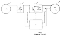
- converters are known, the one rectifier unit, one Intermediate circuit include a power amplifier and a control unit.
- the work according to a procedure of field-oriented regulation, an encoder to the electric motor Mounted speed measurement.
- an encoder for relative An encoder for absolute angular position detection can also be installed, so that highly precise positioning tasks can be solved.
- the encoder is with the motor shaft mechanically, and with the converter, in particular its control unit, electrically connected.
- measuring equipment is used to measure the motor current Value for the motor current recorded at least approximately. It is known the motor current in to detect two of the three phases of a three-phase motor. This then becomes an actual value of the Current vector formed by a control process in the control unit of the Converter is used.
- the control unit also has an important control structure that has a value for one Modeled engine torque.
- This value is a function of the measured motor current values derived current quantities and resistance of the rotor are determined. Since the latter with the inaccuracies described, the torque is also corresponding Inaccuracies. Therefore, such an inverter is unsuitable for tasks that are exact or require the torque values to be set as precisely as possible. Beyond that too Tasks known in which motors jump the setpoint of the torque as possible should follow well. This means that the regulation of the measured torque value is highly dynamic should have.
- the inverters described above are also used for such tasks because of the unsuitable inaccuracies described.
- a radar unit emits a first Antenna emits a radio frequency pulse of an electromagnetic type.
- the frequencies used are at 433MHz as an example, but can also from lower frequencies, such as 100MHz or the like, extend into the range of a few GHz.
- the sensor system has a second antenna on, which receives the high-frequency pulse and an at least partially piezoelectric Body, which then stretches under the effect of the high-frequency voltage and contracts.
- an acoustic surface wave starts, which is a mechanical wave
- Different modes can be pronounced, in particular shear waves, Rayleigh waves, or the like.
- This runs up to reflectors attached to the body, which the acoustic Reflect surface waves at least partially.
- the speed of the surface waves depends on the physical parameters or sizes on the body, such as temperature, pressure, Tensile or shear force fields or the like.
- the reflected parts then run again piezoelectric transducers and are transmitted via the second antenna as electromagnetic radiation emitted.
- the first antenna receives a portion of this radiation.
- the time period until the echo thus created is a measure of physical Parameters or sizes on the body. If only the body temperature is changed, is thus the entire system as a sensor system for temperature measurement on the body usable.
- Such sensor systems can also be configured appropriately be used for torque measurement.
- the invention has for its object to provide a control method for a converter field-oriented control of an electric motor and a converter for field-oriented control to develop an electric motor while avoiding the aforementioned disadvantages.
- the control and regulation process should enable the most accurate setting of a variable and also improve the control dynamics in relation to this size. This size should be the follow the specified setpoint curve, in particular a jump, more precisely.
- the object is in a control method for a converter Field-oriented control of an electric motor solved according to that specified in claim 1
- an adapter can interface between a standardized IEC motor and represent the company's own SEW engine.
- Such an adapter is an example in DE 196 37 361C2 shown.
- An essential feature of the invention in a control method is that on a rotating Part, in particular rotor, shaft, gear or friction wheel, at least one physical variable, such as Temperature, torque, torsion or the like, is measured and this measurement value from the Control unit is used when controlling the engine and / or via a bus system at least one further bus subscriber can be transmitted in such a way that it Control and / or regulating method for a device, ie also for triggering actions, is used, and that for measuring at least one physical variable, in particular of the motor, the gearbox, the angular position encoder or the brake, a method is used is the properties which depend on the respective corresponding physical quantity surface acoustic waves, in particular shear waves, Rayleigh waves, scalar waves or the like from 100 MHz to 100 GHz, exploited or used.
- the main advantage here is that non-contact measurement values can be recorded and the ones used Mass production sensors are inexpensive to manufacture.
- the measured values captured directly on the rotating part.
- This has the advantage that no indirect measurement is carried out or other interconnected measuring systems must be used. In particular the temperature, torsion or torque are measured almost directly at the point of origin. Consequently the measured value is essentially unadulterated.
- the possibility of transmitting the measured value or equivalent sizes via bus system has the advantage that other bus participants, in particular also trigger actions based on a central computer of the bus system can, such as an emergency shutdown or a controlled shutdown of the entire system or Machine. Depending on the selected location of the sensor or sensors, there are different ones Actions executable.
- control method is now able to directly control the values of these variables use and therefore optimally control and regulate the engine, i.e. high control dynamics to show.
- the information about the recorded Measured values encoded or converted into electromagnetic waves and vice versa allows advantageously the information about the recorded measured values at the speed of light can also be transmitted over considerable distances.
- Another advantage is that between measured value processing electronics and measured value recording device none Wire connection must exist. So even a contactless transmission is the Measurement information possible.
- the surface waves are converted directly into electromagnetic waves Waves changed.
- the advantage here is that no further funds are necessary and therefore one simple, fast and inexpensive method and / or means for converting measured values is used.
- the frequency or the Fundamental frequency of surface waves and electromagnetic waves, in particular Radar waves be the same. This is a particularly simple and inexpensive method for Conversion can be used, in particular by using the piezo effect.
- temperature measured values on rotating parts like rotor of the motor, short-circuit cage, input or output shaft of a gear or a gear stage, gear wheel of a gear stage, brake rotor of a brake or pad carrier a brake detected.
- a Action to be triggered This can be done by the converter or by a via Bus system connected bus participants. Emergency stops are examples of such actions or to call controlled shutdown of plants or machines. Also, the reading is from the other bus subscriber or converter to control the motor or other devices usable.
- Temperature can be used for control in a method, for example, in such a way that it does not critical value or actions can be triggered. Especially when the transmission is off is blocked for any reason, the engine without the actions or according to the invention corresponding regulations by further turning such a high temperature, in particular more than 400 ° Celsius, cause the race or even the friction cone to be destroyed. Therefore is a control method according to the invention and a corresponding device advantageous for operational safety, of course, especially in potentially explosive areas.
- the measurement of the torque on the brake rotor include, special methods are advantageously applicable.
- the control of the Function of the brake as mentioned in particular on brake failure.
- the initiation of emergency measures can be carried out.
- Controlled braking action procedures are performed.
- the respective share can be determined by a tax and regulation procedure Control unit can be determined and kept time-dependent.
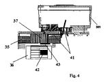
- the device 42 with the first antenna and piezoelectric transducer receives the High-frequency pulse and forwards it to an at least partially piezoelectric body, which then stretches and contracts under the action of the high-frequency voltage. Consequently starts an acoustic on a surface of the device 42, in particular its base plate Surface wave, which can be pronounced as a mechanical wave in different modes, in particular shear waves, Rayleigh waves, or the like. This runs up to the body attached reflectors that at least partially surface acoustic waves reflect. The speed of the surface waves depends on the temperature this area. In the embodiment according to the invention, the surface is thermally conductive with the Rotor connected with a low heat transfer resistance. Hence the Temperature of the surface, which then also affects the speed of the surface waves, in Essentially the same as the temperature of the rotor or its short-circuit cage.
- the parts reflected or reflected on the reflectors run on the surface up to piezoelectric transducers and are transmitted via the second antenna as electromagnetic radiation emitted.
- the first antenna receives a portion of this radiation that is connected to the connected electronics is forwarded for evaluation.
- the length of time until that The resulting echo is a measure of the temperature of the surface or the short-circuit cage.
- Motor parameters such as leakage inductance, resistance of the rotor, Inductance of the rotor or the like, or their model value are sometimes essential temperature-dependent and can constantly with the temperature determined according to the invention updated to be determined.
- the electrical resistance of the rotor is one essential parameter for the control and regulation, since it occurs in the motor equations, that is, the basic physical equations that describe the motor. With the invention certain temperature and knowledge of the material properties can be the electrical Determine the resistance of the rotor very precisely and update it continuously. Therefore, the tax and Control method more precisely and can control the target torque curve in particular better.
- the device with the first Antenna and piezoelectric transducer 42 are not, as shown in the figures, on the Short-circuit cage mounted, but on the rotor 22, 34.
- the device 42 is modified designed and attached to the rotor in such a way that torsion due to the differences in elongation and the resulting deformations can be measured. So that's one Torque corresponding value measurable. This value is used by the control unit Control of the converter used. Because the directly with the torque related value or the torque itself is detected, the control and Ideally control the control method of the control unit to the given setpoint of the torque.
- the introduction of Measures analogous to those already mentioned can be carried out if the torque is very small and / or very large values or a critical value. Likewise with a large one Change speed the triggering of a warning possible. All of these mentioned Measures or actions can be carried out on the one hand by the converter or the control unit, on the other hand, even if there is a fieldbus connection by other bus participants. These other bus subscribers can also be further converters, for example, which then again trigger actions according to the transmitted values for torque or control and regulate accordingly.
- the device is equipped with a first antenna and piezoelectric transducer 42 are used to measure multiple physical quantities.
- piezoelectric transducer 42 are used to measure multiple physical quantities.
- the structure is designed with reflectors and the pulse train or frequency of the high-frequency pulses is selected appropriately.
- the device with the first Antenna and piezoelectric transducer 42 on the movable part such as a brake rotor or the like, or lining carrier of a brake attached to the motor on the B-side. So is measuring the temperature of the moving part and / or measuring the braking torque non-contact measurable. These values are sent to the converter or a fieldbus connected bus participants, such as central computer or the like, passed and from this used for controlling and regulating. For example, when a temperature is exceeded Actions triggered, such as warnings or emergency shutdowns or the like. Also a check the braking torque or triggering actions when critical, very small or too fast large values are executable.
- analogue type triggering actions can be carried out, for example, when the temperature of the Teeth of a gear exceeds a critical value.
- low temperatures are used by the control unit or a bus device connected via fieldbus Taxes and rules used.
- the viscosity of the lubricant is strong temperature-dependent, especially with fluid grease, which even has a phase transition. Consequently the lubricating properties of the interlocking gears change with the Temperature significantly.
- the line from the second antenna to electronics 41 is from the converter through a passage into the interior of the gearbox.
- the line from the second antenna is closed Electronics 41 from the converter through a passage into the motor interior according to FIG. 4 relocated and a passage from the engine interior to the interior of the transmission attached that the radar shafts from the engine interior to the interior of the transmission itself can spread.
- the passage can be a standard hole be executed.
- a hole is used instead of the hole mentioned bidirectional radar wave conductor, for example a hollow waveguide, for transferring the Radar waves from the engine interior are used in the interior of the transmission.
- the A motor Gearbox which comprises at least one gear stage, which acts as an adjusting gear or friction wheel gear is formed, this gear stage at least two gear wheels, namely a friction cone and a race located in contact therewith.
- a measured value for a temperature according to the invention in the manner already described at least temporarily recorded in the area of the frictional contact.
- This measurement is taken from the Control unit of the converter for triggering actions and / or for controlling and regulating used. For example, the speed is reduced to zero or another value.
- this measured value is obtained via a Bus system transmitted to at least one other bus participant.
- the load on the gearbox from the control unit are influenced in such a way that critical temperatures can be avoided.
- An exemplary adjustment gear is known from DE 43 31 944C2.
- the exemplary embodiment according to the invention is a device in such an adjustment gear 42 with first antenna and piezoelectric transducer on the side facing away from the friction contact appropriate.
- One embodiment according to the invention is the device 42 on the motor facing side of the drive pulley with the number 6 of Figure 1 of DE 43 31 944C2 to be installed.
- the drive pulley is a good heat conductor. Therefore, the device 42 Sufficiently thermally coupled with the heat-generating friction contact.
- the engine can be without the actions according to the invention or corresponding regulations by turning one further generate such a high temperature, in particular more than 400 ° Celsius, that the race or even the friction cone is destroyed.
- the invention includes actions or regulations that in time by appropriate control or regulation of devices in advance prevent.
- the output torque is analogous the output shaft of the gearbox mounted on the engine A-side and the value of the control unit or a bus participant supplied.
- the measurement values are only recorded time discreet possible.
- the measurement principle alone makes this clear to a person skilled in the art.
- the repetition frequency can be selected so high that the measured values of the control unit are more frequently used for Can be provided as the repetition rate of the calculations Motor equations of the control units for converters commonly used today.
- the electronics for generating and High frequency evaluation integrated in the converter are integrated in the converter.
- a plurality of devices 42 are used first antenna and piezoelectric transducer on different rotating parts simultaneously the engine, gearbox or brake. Thereby the signals or respective Echoes are coded in such a way that only a single second antenna 43 is sufficient.
- the coding is through corresponding respective arrangement of the reflectors on the surface of the respective devices 42 can be reached with the first antenna and piezoelectric transducer.
Landscapes
- Engineering & Computer Science (AREA)
- Power Engineering (AREA)
- Control Of Electric Motors In General (AREA)
- Control Of Ac Motors In General (AREA)
- Power Steering Mechanism (AREA)
- Control Of Multiple Motors (AREA)
Applications Claiming Priority (2)
| Application Number | Priority Date | Filing Date | Title |
|---|---|---|---|
| DE19942205 | 1999-09-03 | ||
| DE19942205A DE19942205A1 (de) | 1999-09-03 | 1999-09-03 | Steuerverfahren für einen Umrichter zur feldorientierten Regelung eines Elektromotors und Umrichter |
Publications (3)
| Publication Number | Publication Date |
|---|---|
| EP1081845A2 true EP1081845A2 (fr) | 2001-03-07 |
| EP1081845A3 EP1081845A3 (fr) | 2004-01-28 |
| EP1081845B1 EP1081845B1 (fr) | 2007-12-26 |
Family
ID=7920772
Family Applications (1)
| Application Number | Title | Priority Date | Filing Date |
|---|---|---|---|
| EP00116555A Expired - Lifetime EP1081845B1 (fr) | 1999-09-03 | 2000-08-01 | Méthode de commande pour un moteur électrique et dispositif correspondant |
Country Status (3)
| Country | Link |
|---|---|
| EP (1) | EP1081845B1 (fr) |
| AT (1) | ATE382204T1 (fr) |
| DE (2) | DE19942205A1 (fr) |
Cited By (3)
| Publication number | Priority date | Publication date | Assignee | Title |
|---|---|---|---|---|
| EP1148266A1 (fr) * | 2000-04-14 | 2001-10-24 | Knorr-Bremse Systeme für Schienenfahrzeuge GmbH | Appareil et procédé de surveillance de la température des disques de freins à disques |
| WO2021092641A1 (fr) * | 2019-11-13 | 2021-05-20 | Avl List Gmbh | Procédé et système pour étalonner un dispositif de commande d'un moteur électrique |
| US12399068B2 (en) | 2020-12-02 | 2025-08-26 | Pro-Micron Gmbh | Status monitoring for a rotating element of a motor or work machine, more particularly for the rotor of an electric motor |
Families Citing this family (4)
| Publication number | Priority date | Publication date | Assignee | Title |
|---|---|---|---|---|
| DE102005033761A1 (de) * | 2005-07-15 | 2007-01-25 | Sew-Eurodrive Gmbh & Co. Kg | Antrieb und Verfahren |
| DE502008003332D1 (de) | 2007-05-14 | 2011-06-09 | Ebm Papst St Georgen Gmbh & Co | Elektronisch kommutierter Asynchronmotor |
| EP2351992B8 (fr) | 2010-02-01 | 2017-04-12 | CTR Carinthian Tech Research AG | Procédé et agencement de mesure sans contact de paramètres physiques sur des pièces mobiles de machines électriques |
| DE102013208335A1 (de) * | 2013-05-07 | 2014-11-13 | Mahle International Gmbh | Motor und Verfahren zum Antreiben einer Pumpe |
Family Cites Families (4)
| Publication number | Priority date | Publication date | Assignee | Title |
|---|---|---|---|---|
| JPS6036716B2 (ja) * | 1980-11-10 | 1985-08-22 | 富士電機株式会社 | 誘導電動機の磁束ベクトル演算器 |
| EP0619906B1 (fr) * | 1992-01-03 | 1996-03-20 | Siemens Aktiengesellschaft | Capteur passif a ondes de surface pouvant etre interroge sans fil |
| DE19734405B4 (de) * | 1997-08-08 | 2008-05-29 | Sew-Eurodrive Gmbh & Co. Kg | Drehstrommaschine und Verfahren zum Betreiben einer Drehstrommaschine |
| ATE262691T1 (de) * | 1998-01-14 | 2004-04-15 | Heidolph Elektro Gmbh & Co Kg | Verfahren und vorrichtung zum regeln eines antriebsystems einer maschine und/oder einer anlage |
-
1999
- 1999-09-03 DE DE19942205A patent/DE19942205A1/de not_active Withdrawn
-
2000
- 2000-08-01 EP EP00116555A patent/EP1081845B1/fr not_active Expired - Lifetime
- 2000-08-01 DE DE50014872T patent/DE50014872D1/de not_active Expired - Lifetime
- 2000-08-01 AT AT00116555T patent/ATE382204T1/de not_active IP Right Cessation
Cited By (5)
| Publication number | Priority date | Publication date | Assignee | Title |
|---|---|---|---|---|
| EP1148266A1 (fr) * | 2000-04-14 | 2001-10-24 | Knorr-Bremse Systeme für Schienenfahrzeuge GmbH | Appareil et procédé de surveillance de la température des disques de freins à disques |
| US6615954B2 (en) | 2000-04-14 | 2003-09-09 | Knorr-Bremse Systeme Fur Schienenfahrzeuge Gmbh | Monitoring system and method for brake disks |
| WO2021092641A1 (fr) * | 2019-11-13 | 2021-05-20 | Avl List Gmbh | Procédé et système pour étalonner un dispositif de commande d'un moteur électrique |
| US12489383B2 (en) | 2019-11-13 | 2025-12-02 | Avl List Gmbh | Method and system for calibrating a control device of an electric motor |
| US12399068B2 (en) | 2020-12-02 | 2025-08-26 | Pro-Micron Gmbh | Status monitoring for a rotating element of a motor or work machine, more particularly for the rotor of an electric motor |
Also Published As
| Publication number | Publication date |
|---|---|
| DE50014872D1 (de) | 2008-02-07 |
| EP1081845B1 (fr) | 2007-12-26 |
| ATE382204T1 (de) | 2008-01-15 |
| DE19942205A1 (de) | 2001-03-15 |
| EP1081845A3 (fr) | 2004-01-28 |
Similar Documents
| Publication | Publication Date | Title |
|---|---|---|
| DE602005002763T2 (de) | Kodierer und Steuervorrichtung für Motor | |
| WO2011012541A1 (fr) | Procédé et dispositif de surveillance de l'absence d'erreur d'une grandeur de déplacement sur un mécanisme d'entraînement électrique | |
| EP0204164A2 (fr) | Procédé de limitation du nombre de tours du moteur d'entraînement d'une rotative en offset | |
| DE102008054501A1 (de) | Industrieroboter und Verfahren zum Betreiben eines Industrieroboters | |
| EP2023092B1 (fr) | Appareil de mesure de position et procédé de transmission d'une information de mouvement | |
| DE69216287T2 (de) | Betätigungsorgan und Ventilbetätigungssystem | |
| EP1081845B1 (fr) | Méthode de commande pour un moteur électrique et dispositif correspondant | |
| EP2473818A1 (fr) | Dispositif pour mesurer et/ou enregistrer des distances et des variations de distance et dispositif pour mesurer et/ou enregistrer des contraintes mécaniques | |
| DE102011007083A1 (de) | Verfahren zum Steuern des Positionierens eines Aktuators mit einem Wellgetriebe | |
| EP1092867B1 (fr) | Démarreur électrique pour moteur à combustion interne muni d'un dispositif de protection | |
| DE102020117931B3 (de) | Verfahren und elektrischer Flugsteuerungsaktuator mit Einrichtungen zum Erfassen von Fehlern und Abnutzung des Flugsteuerungsaktuators | |
| DE102022120965B4 (de) | Verfahren zum Vorhersagen der Rotortemperatur für einen Elektromotor | |
| EP4026753B1 (fr) | Procédé de détermination de l'usure d'un système de direction d'un véhicule | |
| DE102020116165A1 (de) | Motorsteuervorrichtung mit verbesserter Drehwinkelgenauigkeit | |
| EP3707486B1 (fr) | Procédé et dispositif de mesure de couple dans la transmission de puissance d'un système d'énergie éolienne | |
| EP1217261B1 (fr) | Optimisation des intervalles de temps de vidange d'huile pour une transmission | |
| DE102013217184A1 (de) | Betätigungseinrichtung | |
| DE102004050898B4 (de) | Verfahren und Einrichtung zur Überwachung einer Temperatur eines Lagers einer rotierend umlaufenden Welle | |
| DE102010009165A1 (de) | Verfahren und Vorrichtung zum Steuern eines Tür/Tor-Antriebs | |
| EP4208701A1 (fr) | Procédé et dispositif de détermination d'un rendement et/ou de calibrage d'un couple d'une chaîne cinématique rotative, notamment d'une installation éolienne | |
| EP1524433A1 (fr) | Régulation de vitesse pour éolienne avec deux capteurs de proximité pour mesure de vitesse | |
| EP3120203B1 (fr) | Dispositif et procédé servant à identifier des anomalies dans des machines | |
| DE102015120263B4 (de) | Verfahren zur Verschleißbestimmung, Messgerät, Steuervorrichtung dazu sowie Antriebsvorrichtung umfassend die Steuervorrichtung | |
| DE102012109465B4 (de) | Verfahren und Vorrichtung zur Echtzeitsteuerung eines Antriebstranges | |
| DE102021122500A1 (de) | Verfahren zum Auskuppeln einer Kupplungsvorrichtung und elektrischer Antriebsstrang |
Legal Events
| Date | Code | Title | Description |
|---|---|---|---|
| PUAI | Public reference made under article 153(3) epc to a published international application that has entered the european phase |
Free format text: ORIGINAL CODE: 0009012 |
|
| AK | Designated contracting states |
Kind code of ref document: A2 Designated state(s): AT BE CH CY DE DK ES FI FR GB GR IE IT LI LU MC NL PT SE |
|
| AX | Request for extension of the european patent |
Free format text: AL;LT;LV;MK;RO;SI |
|
| RAP1 | Party data changed (applicant data changed or rights of an application transferred) |
Owner name: SEW-EURODRIVE GMBH & CO. KG |
|
| PUAL | Search report despatched |
Free format text: ORIGINAL CODE: 0009013 |
|
| AK | Designated contracting states |
Kind code of ref document: A3 Designated state(s): AT BE CH CY DE DK ES FI FR GB GR IE IT LI LU MC NL PT SE |
|
| AX | Request for extension of the european patent |
Extension state: AL LT LV MK RO SI |
|
| RIC1 | Information provided on ipc code assigned before grant |
Ipc: 7H 02P 21/00 A Ipc: 7G 01K 5/52 B |
|
| 17P | Request for examination filed |
Effective date: 20040728 |
|
| AKX | Designation fees paid |
Designated state(s): AT BE CH CY DE DK ES FI FR GB GR IE IT LI LU MC NL PT SE |
|
| 17Q | First examination report despatched |
Effective date: 20040910 |
|
| GRAP | Despatch of communication of intention to grant a patent |
Free format text: ORIGINAL CODE: EPIDOSNIGR1 |
|
| RTI1 | Title (correction) |
Free format text: METHOD FOR CONTROLLING AN ELECTRICAL MOTOR AND CORRESPONDING DEVICE |
|
| GRAS | Grant fee paid |
Free format text: ORIGINAL CODE: EPIDOSNIGR3 |
|
| GRAA | (expected) grant |
Free format text: ORIGINAL CODE: 0009210 |
|
| AK | Designated contracting states |
Kind code of ref document: B1 Designated state(s): AT BE CH CY DE DK ES FI FR GB GR IE IT LI LU MC NL PT SE |
|
| REG | Reference to a national code |
Ref country code: GB Ref legal event code: FG4D Free format text: NOT ENGLISH |
|
| REG | Reference to a national code |
Ref country code: IE Ref legal event code: FG4D Free format text: LANGUAGE OF EP DOCUMENT: GERMAN |
|
| REG | Reference to a national code |
Ref country code: CH Ref legal event code: EP |
|
| REF | Corresponds to: |
Ref document number: 50014872 Country of ref document: DE Date of ref document: 20080207 Kind code of ref document: P |
|
| PG25 | Lapsed in a contracting state [announced via postgrant information from national office to epo] |
Ref country code: SE Free format text: LAPSE BECAUSE OF FAILURE TO SUBMIT A TRANSLATION OF THE DESCRIPTION OR TO PAY THE FEE WITHIN THE PRESCRIBED TIME-LIMIT Effective date: 20080326 |
|
| GBT | Gb: translation of ep patent filed (gb section 77(6)(a)/1977) |
Effective date: 20080414 |
|
| PG25 | Lapsed in a contracting state [announced via postgrant information from national office to epo] |
Ref country code: NL Free format text: LAPSE BECAUSE OF FAILURE TO SUBMIT A TRANSLATION OF THE DESCRIPTION OR TO PAY THE FEE WITHIN THE PRESCRIBED TIME-LIMIT Effective date: 20071226 Ref country code: FI Free format text: LAPSE BECAUSE OF FAILURE TO SUBMIT A TRANSLATION OF THE DESCRIPTION OR TO PAY THE FEE WITHIN THE PRESCRIBED TIME-LIMIT Effective date: 20071226 |
|
| NLV1 | Nl: lapsed or annulled due to failure to fulfill the requirements of art. 29p and 29m of the patents act | ||
| PG25 | Lapsed in a contracting state [announced via postgrant information from national office to epo] |
Ref country code: ES Free format text: LAPSE BECAUSE OF FAILURE TO SUBMIT A TRANSLATION OF THE DESCRIPTION OR TO PAY THE FEE WITHIN THE PRESCRIBED TIME-LIMIT Effective date: 20080406 |
|
| PG25 | Lapsed in a contracting state [announced via postgrant information from national office to epo] |
Ref country code: PT Free format text: LAPSE BECAUSE OF FAILURE TO SUBMIT A TRANSLATION OF THE DESCRIPTION OR TO PAY THE FEE WITHIN THE PRESCRIBED TIME-LIMIT Effective date: 20080526 |
|
| REG | Reference to a national code |
Ref country code: IE Ref legal event code: FD4D |
|
| PG25 | Lapsed in a contracting state [announced via postgrant information from national office to epo] |
Ref country code: DK Free format text: LAPSE BECAUSE OF FAILURE TO SUBMIT A TRANSLATION OF THE DESCRIPTION OR TO PAY THE FEE WITHIN THE PRESCRIBED TIME-LIMIT Effective date: 20071226 Ref country code: IE Free format text: LAPSE BECAUSE OF FAILURE TO SUBMIT A TRANSLATION OF THE DESCRIPTION OR TO PAY THE FEE WITHIN THE PRESCRIBED TIME-LIMIT Effective date: 20071226 |
|
| PLBE | No opposition filed within time limit |
Free format text: ORIGINAL CODE: 0009261 |
|
| STAA | Information on the status of an ep patent application or granted ep patent |
Free format text: STATUS: NO OPPOSITION FILED WITHIN TIME LIMIT |
|
| 26N | No opposition filed |
Effective date: 20080929 |
|
| PG25 | Lapsed in a contracting state [announced via postgrant information from national office to epo] |
Ref country code: GR Free format text: LAPSE BECAUSE OF FAILURE TO SUBMIT A TRANSLATION OF THE DESCRIPTION OR TO PAY THE FEE WITHIN THE PRESCRIBED TIME-LIMIT Effective date: 20080327 |
|
| PG25 | Lapsed in a contracting state [announced via postgrant information from national office to epo] |
Ref country code: MC Free format text: LAPSE BECAUSE OF NON-PAYMENT OF DUE FEES Effective date: 20080831 |
|
| REG | Reference to a national code |
Ref country code: CH Ref legal event code: PL |
|
| PG25 | Lapsed in a contracting state [announced via postgrant information from national office to epo] |
Ref country code: LI Free format text: LAPSE BECAUSE OF NON-PAYMENT OF DUE FEES Effective date: 20080831 Ref country code: CH Free format text: LAPSE BECAUSE OF NON-PAYMENT OF DUE FEES Effective date: 20080831 |
|
| PG25 | Lapsed in a contracting state [announced via postgrant information from national office to epo] |
Ref country code: BE Free format text: LAPSE BECAUSE OF NON-PAYMENT OF DUE FEES Effective date: 20080831 Ref country code: CY Free format text: LAPSE BECAUSE OF FAILURE TO SUBMIT A TRANSLATION OF THE DESCRIPTION OR TO PAY THE FEE WITHIN THE PRESCRIBED TIME-LIMIT Effective date: 20071226 |
|
| PG25 | Lapsed in a contracting state [announced via postgrant information from national office to epo] |
Ref country code: AT Free format text: LAPSE BECAUSE OF NON-PAYMENT OF DUE FEES Effective date: 20080801 |
|
| PGFP | Annual fee paid to national office [announced via postgrant information from national office to epo] |
Ref country code: FR Payment date: 20090717 Year of fee payment: 10 |
|
| PGFP | Annual fee paid to national office [announced via postgrant information from national office to epo] |
Ref country code: GB Payment date: 20090729 Year of fee payment: 10 |
|
| PG25 | Lapsed in a contracting state [announced via postgrant information from national office to epo] |
Ref country code: LU Free format text: LAPSE BECAUSE OF NON-PAYMENT OF DUE FEES Effective date: 20080801 |
|
| PG25 | Lapsed in a contracting state [announced via postgrant information from national office to epo] |
Ref country code: IT Free format text: LAPSE BECAUSE OF NON-PAYMENT OF DUE FEES Effective date: 20080831 |
|
| GBPC | Gb: european patent ceased through non-payment of renewal fee |
Effective date: 20100801 |
|
| REG | Reference to a national code |
Ref country code: FR Ref legal event code: ST Effective date: 20110502 |
|
| PG25 | Lapsed in a contracting state [announced via postgrant information from national office to epo] |
Ref country code: FR Free format text: LAPSE BECAUSE OF NON-PAYMENT OF DUE FEES Effective date: 20100831 |
|
| PG25 | Lapsed in a contracting state [announced via postgrant information from national office to epo] |
Ref country code: GB Free format text: LAPSE BECAUSE OF NON-PAYMENT OF DUE FEES Effective date: 20100801 |
|
| PGFP | Annual fee paid to national office [announced via postgrant information from national office to epo] |
Ref country code: DE Payment date: 20190831 Year of fee payment: 20 |
|
| REG | Reference to a national code |
Ref country code: DE Ref legal event code: R071 Ref document number: 50014872 Country of ref document: DE |