EP2023092B1 - Appareil de mesure de position et procédé de transmission d'une information de mouvement - Google Patents
Appareil de mesure de position et procédé de transmission d'une information de mouvement Download PDFInfo
- Publication number
- EP2023092B1 EP2023092B1 EP08008550A EP08008550A EP2023092B1 EP 2023092 B1 EP2023092 B1 EP 2023092B1 EP 08008550 A EP08008550 A EP 08008550A EP 08008550 A EP08008550 A EP 08008550A EP 2023092 B1 EP2023092 B1 EP 2023092B1
- Authority
- EP
- European Patent Office
- Prior art keywords
- value
- movement
- unit
- measuring unit
- correction value
- Prior art date
- Legal status (The legal status is an assumption and is not a legal conclusion. Google has not performed a legal analysis and makes no representation as to the accuracy of the status listed.)
- Not-in-force
Links
- 230000033001 locomotion Effects 0.000 title claims description 69
- 238000000034 method Methods 0.000 title claims description 16
- 238000012937 correction Methods 0.000 claims description 42
- 238000005259 measurement Methods 0.000 claims description 22
- 238000005070 sampling Methods 0.000 claims description 20
- 230000006870 function Effects 0.000 claims description 9
- 230000005540 biological transmission Effects 0.000 description 29
- 230000001133 acceleration Effects 0.000 description 7
- 238000004364 calculation method Methods 0.000 description 6
- 230000001419 dependent effect Effects 0.000 description 4
- 230000000694 effects Effects 0.000 description 4
- 238000010586 diagram Methods 0.000 description 3
- 230000001965 increasing effect Effects 0.000 description 3
- 238000012545 processing Methods 0.000 description 3
- 238000013213 extrapolation Methods 0.000 description 2
- 238000013139 quantization Methods 0.000 description 2
- 238000013459 approach Methods 0.000 description 1
- 230000002457 bidirectional effect Effects 0.000 description 1
- 125000004122 cyclic group Chemical group 0.000 description 1
- 238000005516 engineering process Methods 0.000 description 1
- 238000002474 experimental method Methods 0.000 description 1
- 238000010438 heat treatment Methods 0.000 description 1
- 230000001939 inductive effect Effects 0.000 description 1
- 230000005291 magnetic effect Effects 0.000 description 1
- 238000004519 manufacturing process Methods 0.000 description 1
- 230000003287 optical effect Effects 0.000 description 1
- 230000004044 response Effects 0.000 description 1
- 238000004904 shortening Methods 0.000 description 1
- 230000001360 synchronised effect Effects 0.000 description 1
- 230000002123 temporal effect Effects 0.000 description 1
- 238000013519 translation Methods 0.000 description 1
Images


Classifications
-
- G—PHYSICS
- G01—MEASURING; TESTING
- G01D—MEASURING NOT SPECIALLY ADAPTED FOR A SPECIFIC VARIABLE; ARRANGEMENTS FOR MEASURING TWO OR MORE VARIABLES NOT COVERED IN A SINGLE OTHER SUBCLASS; TARIFF METERING APPARATUS; MEASURING OR TESTING NOT OTHERWISE PROVIDED FOR
- G01D3/00—Indicating or recording apparatus with provision for the special purposes referred to in the subgroups
Definitions
- the invention relates to a position measuring device according to claim 1, as well as a method for transmitting motion information according to claim 12.
- a position measuring device is particularly suitable for use in a drive system.
- a position measuring device according to the invention, or a method according to the invention it is possible, in addition to the position data, to very efficiently transmit motion information, in particular speed and / or acceleration information, to a drive controller.
- In automation technology drives are often used whose motors are controlled by a numerical control (NC).
- the controller generates setpoints in accordance with a program to be executed, which are converted into drive signals for the motor in corresponding motor control modules, so-called inverters.
- the movement resulting from the drive signals can be both a longitudinal movement, for example the method of a tool slide in a machine tool, as well as a rotational movement, for example, a with a certain Speed rotating tool spindle or the rotation of a joint of a manufacturing robot, his.
- position measuring devices In order to be able to measure the extent of the movement, position measuring devices are used, in the case of a longitudinal movement about linear position measuring devices, in rotary movements corresponding rotational position measuring devices, so-called.
- Rotary encoder which are coupled directly or via a translation with a motor shaft.
- the controller calls up position actual values from the position measuring devices, with the aid of which it again determines new setpoint values for the inverters.
- Such control circuits allow precise control of the drive.
- the transmission of the position values from the position measuring devices to the control can be purely analog, often in the form of two mutually phase-shifted by 90 ° sinusoidal signals, or digital, in the form of rectangular Zählsignalen or by transferring complex data via data interfaces.
- position measuring devices especially serial data interfaces are preferred today, since they require only a small number of lines for data transmission and enable the transmission of absolute position values.
- the drive control needs not only the actual position values but also other movement data, such as the current speed or speed, or the acceleration.
- the velocity can be derived from two consecutively measured position values by forming the difference quotient given a known controller cycle time.
- the acceleration can be determined with the aid of three consecutively measured position values, or two consecutively calculated speed values.
- motion values calculated in this way always only reflect an average value with which the controlled drive has covered the path from the first to the second and possibly to the third position.
- the actual speed of a drive at a certain time of measurement may differ significantly from the average value.
- This may, for example, mechanical causes, such as imbalances in the motor shafts, friction effects or load changes, such as caused by the engagement of a tool in a workpiece.
- errors of the position measuring device in particular quantization errors, are particularly problematic since they have the greater effect, the shorter the controller cycle time and the smaller the resulting difference between two consecutively measured position values.
- the average value which is based on successively measured position values, used to determine a new speed setpoint, due to the discrepancy between the actual speed at the measurement time and the average value unwanted control fluctuations may occur, which leads to a heating of the engine of the drive, to disturbing noise or can cause vibration due to resonance effects.
- Modern position measuring devices in particular those which are capable of performing complex arithmetic operations by the use of highly integrated signal processing units, for example in the form of a microcontroller or corresponding structures in a user-specific integrated component (ASIC), can often already carry out their own motion values, in particular speed and acceleration values determine with high accuracy. Since in this case, however, both the current position value and at least one movement value, for example the speed value, must be transmitted from the position measuring device to the controller, the time available to the controller after receiving the current actual values is reduced when the controller cycle time is constant Perform calculations to determine the new setpoints. For this reason, especially when the data transmission is via serial interfaces, this variant is often not applicable, because an increase in the data transmission rate is associated with a high cost of material and costs.
- highly integrated signal processing units for example in the form of a microcontroller or corresponding structures in a user-specific integrated component (ASIC)
- ASIC user-specific integrated component
- a position measuring device with a position measuring unit, a movement measuring unit, a computing unit and an interface unit is proposed, wherein position values of two objects movably arranged relative to one another in a measuring direction can be measured with the position measuring unit, with the movement measuring unit a movement value of the two arranged movably relative to one another in a measuring direction Objects is determined and the position values and the movement value of the arithmetic unit are supplied, which determines a motion information in the form of a correction value which is suitable for subsequent electronics from a current position value, at least one previous position value, a controller cycle time, the time interval between the Specify measurements of position values and calculate the motion value to the correction value and the data word width of the correction value is substantially smaller than the data word width of the motion value.
- FIG. 1 shows a block diagram of a position measuring device according to the invention 1. It includes a position measuring unit 10 for measuring position values of two objects movable relative to one another in a measuring direction, a movement measuring unit 20 for determining movement values of the two objects, a computing unit 30 for determining correction values from position values and movement values, and an interface unit 40.
- a data channel 50 connects the interface unit 40 of the position measuring device 1 with an interface unit 110 of sequential electronics 100, for example a drive control 100.
- the drive control 100 further comprises a control unit 120 whose controller cycle time T R is determined by a controller clock generator 130.
- the movement measuring unit 20 is a speed measuring unit 20 with the speed values v of the two objects movable relative to one another in a measuring direction. It should be expressly pointed out at this point that the present invention is also applicable to other movement values, in particular acceleration values.
- the two objects movably arranged relative to one another in a measuring direction can be, for example, the rotor and stator of an electric motor, or a tool carriage which is movably arranged on a machine table of a machine tool.
- the position and velocity values are angular positions and velocities, while in the second case linear positions and velocities are measured.
- the data channel 50 and the interface units 40, 110 of the position measuring device 1 and the drive control 100 are designed such that a bidirectional data transmission is enabled via them.
- data request commands RQ to the position measuring device 1 and data determined in the position measuring device 1 can be sent to the drive controller 100 by the drive controller 100.
- a serial interface connection is used as the data channel 50, since in this case the number of lines required for the data transmission is low and thus the wiring effort can be reduced.
- the Drive control 100 that is, for example, when the motor of a feed axis of a machine tool or a robot joint is controlled, the transmission of data request commands RQ is carried out continuously at a time interval of the controller cycle time T R.
- Typical controller cycle times T R are, for example, 50 ⁇ s to 2 ms.
- the data request commands RQ are forwarded in the position measuring device 1 from the interface unit 40 via a data request line 41 to the position measuring unit 10, the speed measuring unit 20 and the arithmetic unit 30. If a data request command RQ reaches the position measuring unit 10, it determines a current position value P n and transmits it to the interface unit 40 and the arithmetic unit 30.
- the value of the average speed v D is erroneous since, on the one hand, the actual speed profile is not taken into account and thus the actual speed value v at the desired measuring time, in the present example at the time of arrival of the data request command RQ, may deviate from the average speed v D and on the other hand Errors in the position values P n , P n-1 , in particular quantization errors, are included in the calculation.
- the values for the controller cycle time T R and the previous position value P n-1 can be stored, for example, in the arithmetic unit 30 in a memory 31.
- the controller cycle time T R are written by the drive controller 100 via the data channel 50 in the memory 31.
- the position measuring device 1 can be easily adapted to different drive controllers 100 with different controller cycle times T R.
- the controller cycle time T R in the arithmetic unit 30 can be measured, so that, for example, variable controller cycle times T R can also be taken into account.
- the measurement of the controller cycle time T R can be effected, for example, by means of a counter which is operated with a clock signal which has a substantially shorter period duration than the controller cycle time T R. From the difference of the count between two data request commands RQ and the period of the clock signal, the controller cycle time T R can be calculated.
- a clock signal for operation of the counter for example, in the description of the FIG. 3 described sampling clock signal of the speed measuring unit 20 can be used.
- the current position value P n , the previous position value P n-1 and the controller cycle time T R are also available to the drive controller 100. Therefore, as described in the introduction, the value of the average speed v D can also be determined in the drive controller 100. Since the thus determined average speed v D , as also described in the introduction, may deviate in practice from the actual speed of the drive at the time of interrogation, transmission of the current speed value v due to the associated increased transmission time duration is undesirable, the arithmetic unit 30 determines from the average speed v D and the current speed value v determined in the speed measuring unit 20, a correction value K, with the aid of which in the drive control 100 using the current position value P n , the previous position value P n-1 and the controller cycle time T R, the current speed value v is determinable.
- the correction value K has a much smaller data word width than the current speed value v. This will be a Transmission of the information about the current speed value v with a moderate increase of the transmission time allows.
- the data word width of the speed value v is dependent on several factors, including the data word width and thus the resolution of the position measuring unit 10, the maximum permitted speed, ie the maximum speed of a rotary position measuring device or the maximum feed rate of a linear position measuring device, as well as the required resolution of Speed value v.
- the data word width of the speed value v must be set in the range of the data word width of the current position value P n , which may be 20 bits, for example.
- the speed value v determined in the position measuring device 1 has a higher resolution than the average speed v D calculated according to equation 1.
- the correction value K transmitted to the drive control 100 now makes it possible to transmit the speed information with a higher resolution without significantly increasing the data volume.
- the correction value K for the transmission of the speed information can be both a position correction value K P , a movement correction value K V (in the present example a speed correction value K V ), and a time correction value K T.
- FIGS. 2a to 2c illustrate the temporal advantage in the transmission of motion information using the example of the speed information with a position measuring device 1 according to the invention over the methods known in the prior art. It shows FIG. 2a the known variant, in which only the position value P is transmitted and the speed in the subsequent electronics is determined by calculating the average speed v D , while in FIG. 2b Both the position value P, and the speed value v is transmitted, which has a massive increase in transmission time result. Figure 2c finally shows the transmission according to the invention of position value P and correction value K.
- the transmission of the requested data can take place, for example, in the form of data packets which each begin with an initial sequence A and terminate with an end sequence E.
- the initial sequence A may only be a start bit, but identification information, etc., may also be transmitted.
- the end sequence E can only consist of one stop bit, or contain additional information, for example a checksum for ensuring data security (CRC, cyclic redundancy check).
- the transmission of the data packets is in response to the receipt of a data request command RQ written in the FIGS. 2a to 2c only greatly simplified as arrow is indicated.
- the time interval between two successive data request commands RQ corresponds to the controller cycle time T R.
- the data request command RQ can also be sent as part of a data packet and that in practice between the arrival of the data request command RQ and the transmission of the requested data, a certain time can pass for the processing of the data in the position measuring device 1 ,
- FIGS. 2a to 2c applies equally and is not relevant to the present invention, a detailed description is omitted.
- the data packet consists of initial sequence A, position value P and end sequence E.
- the transmission time T T necessary for the transmission of the data packet from the position measuring device 1 to the drive control 100 is very short, which has the result that the calculation time T C , that of the drive control 100 for the calculation the new setpoint values for the control loops for controlling the drive assigned to the position measuring device 1 is available is quite long. In this case, however, as already discussed in detail, since the drive controller 100 is dependent on using the average speed v D between two successive position values P as the actual value for the speed, this variant is quite inaccurate in practice.
- the data packet still contains the velocity value v determined in the position measuring device 1.
- the drive control 100 thus has the exact speed value v available for the calculation of the new setpoint values. Since the data word width of the speed value v is in the range of the data word width of the position value P, this variant leads to a significantly longer transmission time T T , or to a shortening of the computing time T C , which is the drive controller 100 available. This can lead to compromises in terms of computational accuracy when calculating the new actual values for the control, or the controller cycle time T R has to be increased. Both deteriorate the dynamics of the drive control and is therefore undesirable.
- Figure 2c now shows a data packet consisting of initial sequence A, position value P, correction value K and end sequence E. Since the data word width of the correction value K for calculating the speed value v from position values P, the controller cycle time T R and the correction value K in the drive controller 100 can be selected substantially smaller than the data word width of the speed value v, this variant only leads to an insignificant increase in the transmission time period T T and thus to an insignificant reduction of the computing time T C.
- the speed measuring unit 20 uses the position measuring unit 10 to detect the actual course of the position as a function of time by measuring auxiliary position values PH.
- the speed measuring unit 20 comprises in FIG. 1 a sampling clock generator 22 which generates a sampling clock signal having a period T H which determines the intervals at which auxiliary position values PH are requested from the position measuring unit 10.
- the request of auxiliary position values PH is made by means of auxiliary data request commands RQH, which are sent to the position measuring unit 10 via an auxiliary position request line 21.
- auxiliary average speeds can now be calculated analogously to the calculation of the average velocity v D , by means of which suitable extrapolation or interpolation algorithms, such as spline or polynomial interpolation or other filter functions, an approximation function is formed on the actual speed profile and, in turn, the speed value v at a desired point in time can be determined therefrom.
- suitable extrapolation or interpolation algorithms such as spline or polynomial interpolation or other filter functions
- the sampling clock has at least twice the frequency as the controller clock, which means that per measured position value P n , P n-1 at least two auxiliary position values PH are generated. Since the accuracy of the approach to the actual speed curve increases with the number of detected average speeds, or the number of measured auxiliary position values PH, the highest possible frequency of the sampling clock signal should be sought. This is opposed by a limited processing speed of the position measuring unit 10, the speed measuring unit 20 and the arithmetic unit 30. Experiments have shown that already very good results can be achieved when the frequency for the sampling clock signal is selected to be four to thirty-two times the frequency of the regulator clock signal.
- an acceleration value a can also be determined with the aid of the speed profile defined by the auxiliary average speeds, i. the speed measurement unit 20 can be easily further developed into an acceleration measurement unit 20.
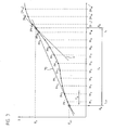
- FIG. 3 shows an example of a position profile in a measuring direction X as a function of the time t.
- the time t n-1 indicates the time at which the preceding position value P n-1 was measured in the preceding measuring cycle.
- the current position value P n is measured in the current measuring cycle as a result of the arrival of a data request command RQ from the drive controller 100.
- the time interval between the times t n-1 and t n corresponds to the controller cycle time T R.
- the average velocity v D is calculated as indicated in equation 1. The value thus determined corresponds to the slope of the straight line v D.
- the actual velocity value v for example at time t n , corresponds to the slope of the straight line v representing a tangent to the actual position history at the position of the current position value P n .
- the speed measuring unit 20 requests auxiliary position values PH 1 to PH 10 from the position measuring unit 10 at auxiliary times tH 1 to tH 10 at intervals of the period TH of the sampling clock signal.
- the speed value v is now formed.
- the sampling clock signal and the regulator clock signal are generated by different clock sources, on the one hand the sampling clock generator 22 in the position measuring device 1, and on the other hand, the controller clock generator 130 in the drive controller 100, to avoid beat effects, it is particularly advantageous if the clock signals can be synchronized.
- the times t n , t n-1 can be used in the position measuring device 1 , to which data request commands RQ from the drive controller 100 arrive.
- the sampling clock signal has an integer multiple of the frequency of the regulator clock signal, the further advantage is that the measurement instant t n largely coincides with one of the measurement times of the auxiliary position values PH and thus the corresponding auxiliary position value PH can be equated with the current position value P n .
- auxiliary position values PH which are measured after the arrival of the data request command RQ can also be used to determine the speed value v.
- This is in FIG. 3 is indicated by the auxiliary position values PH 11 to PH 13 , which are measured after the data request command RQ arriving at time t n at auxiliary times tH 11 to tH 13 .
- speed information can be transmitted to the drive control 100, which corresponds to the speed of the drive a defined time after the arrival of the data request command RQ.
- the drive control 100 has an even more current speed value v as the actual value.
- a higher accuracy for the speed value v can be achieved than through Extrapolation, which must be applied when the last auxiliary position value PH 13 is measured before the time of determining the velocity value v.
- the position measuring unit 10 can be both an incremental system and an absolute system. Likewise, the physical sensing principle underlying the position measurement unit 10 is not relevant to the present invention. For example, the position measuring unit 10 can be based on an optical, magnetic, inductive or capacitive measuring principle.
- position measuring device 1 in the functional blocks position measuring unit 10, speed measuring unit 20, arithmetic unit 30 and interface unit 40 has been made only for better understanding. In practice, several, or even all function blocks can be integrated in a highly integrated user-specific component (ASIC). Likewise, a microcontroller can be used to implement at least part of the functional blocks.
- ASIC application-specific integrated circuit
Landscapes
- Physics & Mathematics (AREA)
- General Physics & Mathematics (AREA)
- Transmission And Conversion Of Sensor Element Output (AREA)
- Arrangements For Transmission Of Measured Signals (AREA)
- Length Measuring Devices With Unspecified Measuring Means (AREA)
- Control Of Position Or Direction (AREA)
- Numerical Control (AREA)
Claims (17)
- Appareil de mesure de position avec une unité de mesure de position (10), une unité de mesure de mouvement (20), une unité de calcul (30) et une unité d'interface (40), dans lequel- avec l'unité de mesure de position (10), on peut mesurer des valeurs de position (P ; Pn, Pn-1) de deux objets disposés de manière mobile l'un par rapport à l'autre dans une direction de mesure,- avec l'unité de mesure de mouvement (20), on peut déterminer une valeur de mouvement (v) des deux objets disposés de manière mobile l'un par rapport à l'autre dans une direction de mesure,- les valeurs de position (P ; Pn, Pn-1) et la valeur de mouvement (v) sont acheminées vers l'unité de calcul (30) qui détermine une information de mouvement sous la forme d'une valeur de correction (K) apte à indiquer dans une électronique de suivi (100) à partir d'une valeur courante de position (Pn), au moins une valeur de position antérieure (Pn-1) d'une durée de cycle de régulation (TR) indiquant la distance temporelle entre les mesures de valeurs de positions (P ; Pn, Pn-1) et à calculer la valeur de correction (K) de la valeur de mouvement (v) et la longueur des mots de données de la valeur de correction (K) est sensiblement inférieure à la longueur des mots de données de la valeur de mouvement (v).
- Appareil de mesure de position selon la revendication 1, dans lequel l'unité d'interface (40) est reliée par l'intermédiaire d'une ligne de requête de données (41) à l'unité de mesure de position (10), à l'unité de mesure de mouvement (20) et à l'unité de calcul (30), celle-ci permettant de transmettre les ordres de requête de données (RQ) qui arrivent à l'unité d'interface (40) en provenance de l'électronique de suivi (100).
- Appareil de mesure de position selon la revendication 2, dans lequel les ordres de requête de données (RQ) arrivent à l'unité d'interface (40) au rythme de la durée du cycle de régulation (TR).
- Appareil de mesure de position selon la revendication 1, dans lequel la valeur courante de la position (Pn) et la valeur de correction (K) sont acheminées vers l'unité d'interface (40) et peuvent être transmises de l'unité d'interface (40) à l'électronique de suivi (100).
- Appareil de mesure de position selon une des revendications précédentes, dans lequel la valeur de correction (K) est une valeur de correction de position (KP) ou une valeur de correction de mouvement (Kv) ou une valeur de correction du temps (KT).
- Appareil de mesure de position selon une des revendications précédentes, dans lequel l'unité de calcul (30) comprend de plus une mémoire (31) dans laquelle il est possible de mémoriser la durée de cycle de régulation (TR) et/ou des valeurs de position (P ; Pn, Pn-1).
- Appareil de mesure de position selon une des revendications précédentes, dans lequel l'unité d'interface (40) est reliée à une unité d'interface (110) de l'électronique de suivi (100) par l'intermédiaire d'un canal de données (50).
- Appareil de mesure de position selon une des revendications précédentes, dans lequel le canal de données (50) est une liaison série d'interfaces.
- Appareil de mesure de position selon une des revendications précédentes, dans lequel l'unité de mesure de mouvement (20) comprend un générateur d'horloge d'exploration (22) qui génère un signal d'horloge d'exploration avec une durée de période (TH) et l'unité de mesure de mouvement (20) est reliée à l'unité de mesure de position (10) par l'intermédiaire d'une ligne auxiliaire de requête de données (21) permettant de requérir des valeurs auxiliaires de position (PH ; PH1 à PH13) de l'unité de mesure de position (10) à l'aide d'ordres auxiliaires de requête de positions (RQH).
- Appareil de mesure de position selon la revendication 9, dans lequel la requête de valeurs auxiliaires de position (PH ; PH1 à PH13) s'effectue au rythme de la durée de la période (TH) du signal d'horloge d'exploration et les valeurs auxiliaires de position (PH ; PH1 à PH13) sont acheminées vers l'unité de mesure de mouvement (20), dans laquelle la valeur de mouvement (v) à un instant de mesure (tn) peut être déterminée en formant une fonction d'approximation du déroulement du mouvement à partir des valeurs auxiliaires de position (PH ; PH1 à PH13) et de la durée de la période (TH) du signal d'horloge d'exploration.
- Appareil de mesure de position selon une des revendications précédentes, dans lequel l'unité de mesure de mouvement (20) est une unité de mesure de vitesse (20) et la valeur de mouvement (v) est une valeur de vitesse (v).
- Procédé de détermination d'une valeur de correction (K) pour la transmission d'une information de mouvement à partir d'un appareil de mesure de position (1) vers une électronique de suivi (100), dans lequel l'appareil de mesure de position (1) comprend une unité de mesure de position (10), une unité de mesure de mouvement (20), une unité de calcul (30) et une unité d'interface (40), avec les étapes suivantes :- mesure dans l'unité de mesure de position (10) d'une valeur courante de position (Pn) de deux objets disposés de manière mobile l'un par rapport à l'autre dans une direction de mesure,- détermination dans l'unité de mesure de mouvement (20) d'une valeur de mouvement (v) des deux objets disposés de manière mobile l'un par rapport à l'autre dans une direction de mesure et- détermination dans l'unité de calcul (30) de la valeur de correction (K), la valeur de correction (K) dans l'électronique de suivi (100) indiquant à partir de la valeur courante de position (Pn), au moins une valeur de position antérieure (Pn-1) mesurée dans un cycle de mesure antérieur et une durée de cycle de régulation (TR) indiquant la distance temporelle entre les mesures de valeurs de positions (P ; Pn, Pn-1), ce qui permet de calculer la valeur de mouvement (v) et la longueur des mots de données de la valeur de correction (K) qui est sensiblement inférieure à la longueur des mots de données de la valeur de mouvement (v).
- Procédé selon la revendication 12, dans lequel la détermination de la valeur courante de position (Pn), de la valeur de mouvement (v) et de la valeur de correction (K) s'effectue après réception d'un ordre de requête de données (RQ) envoyé par l'électronique de suivi (100) à l'unité d'interface (40) de l'appareil de mesure de position (1).
- Procédé selon une des revendications 12 ou 13, dans lequel la valeur courante de position (Pn) et la valeur de correction (K) sont transmises à l'électronique de suivi (100) par l'intermédiaire de l'unité d'interface (40).
- Procédé selon une des revendications 12 à 14, dans lequel la valeur de correction (K) est une valeur de correction de position (KP) ou une valeur de correction de mouvement (KV) ou une valeur de correction du temps (KT).
- Procédé selon une des revendications 12 à 15, dans lequel l'unité de mesure de mouvement (20) comprend de plus un générateur d'horloge d'exploration (22) qui génère un signal d'horloge d'exploration avec une durée de période (TH) et l'unité de mesure de mouvement (20) est reliée à l'unité de mesure de position (10) par l'intermédiaire d'une ligne auxiliaire de requête de données (21) permettant de requérir des valeurs auxiliaires de position (PH ; PH1 à PH13) de l'unité de mesure de position (10) à l'aide d'ordres auxiliaires de requête de positions (RQH) et la détermination de la valeur de mouvement (v) comprend les étapes suivantes :- requête de valeurs auxiliaires de position (PH ; PH1 à PH13) au rythme de la durée de la période (TH) du signal d'horloge d'exploration,- formation de valeurs auxiliaires de mouvement à partir des valeurs auxiliaires de position (PH ; PH1 à PH13) et de la durée de la période (TH) du signal d'horloge d'exploration,- formation d'une fonction d'approximation du déroulement du mouvement à partir des valeurs auxiliaires de mouvement et- détermination de la valeur de mouvement (v) à un instant de mesure (tn) à partir de la fonction d'approximation.
- Procédé selon une des revendications 12 à 16, dans lequel l'unité de mesure de mouvement (20) est une unité de mesure de vitesse (20) qui détermine une valeur de vitesse (v) comme valeur de mouvement (v).
Applications Claiming Priority (1)
| Application Number | Priority Date | Filing Date | Title |
|---|---|---|---|
| DE102007036542A DE102007036542A1 (de) | 2007-08-02 | 2007-08-02 | Positionsmessgerät und Verfahren zur Übertragung einer Bewegungsinformation |
Publications (3)
| Publication Number | Publication Date |
|---|---|
| EP2023092A2 EP2023092A2 (fr) | 2009-02-11 |
| EP2023092A3 EP2023092A3 (fr) | 2012-03-21 |
| EP2023092B1 true EP2023092B1 (fr) | 2012-10-31 |
Family
ID=39951637
Family Applications (1)
| Application Number | Title | Priority Date | Filing Date |
|---|---|---|---|
| EP08008550A Not-in-force EP2023092B1 (fr) | 2007-08-02 | 2008-05-07 | Appareil de mesure de position et procédé de transmission d'une information de mouvement |
Country Status (5)
| Country | Link |
|---|---|
| US (1) | US7925462B2 (fr) |
| EP (1) | EP2023092B1 (fr) |
| JP (1) | JP5317568B2 (fr) |
| CN (1) | CN101358844B (fr) |
| DE (1) | DE102007036542A1 (fr) |
Families Citing this family (9)
| Publication number | Priority date | Publication date | Assignee | Title |
|---|---|---|---|---|
| JP4351281B2 (ja) * | 2007-12-13 | 2009-10-28 | ファナック株式会社 | 5軸加工機を制御する数値制御装置 |
| DE102011103735B4 (de) * | 2010-12-10 | 2018-08-23 | Sew-Eurodrive Gmbh & Co Kg | Verfahren und Vorrichtung zur zyklischen digitalen Übertragung eines Positionswertes eines bewegten Objektes mit träger Masse |
| DE102011006300A1 (de) * | 2011-03-29 | 2012-10-04 | Dr. Johannes Heidenhain Gmbh | Verfahren und Überwachungseinheit zur Überprüfung von Positionswerten |
| AU2012272221B2 (en) | 2011-06-20 | 2015-05-07 | Sew-Eurodrive Gmbh & Co. Kg | Method and device for the cyclic digital transmission of a position value of a moving object with inertial mass |
| DE102013219277A1 (de) * | 2013-09-25 | 2015-03-26 | Dr. Johannes Heidenhain Gmbh | Positionsmesseinrichtung und Verfahren zur Überprüfung eines Arbeitstaktsignals |
| DE102016212115A1 (de) * | 2016-07-04 | 2018-01-04 | Dr. Johannes Heidenhain Gmbh | Vorrichtung und Verfahren zur Datenübertragung |
| JP6877169B2 (ja) * | 2017-02-14 | 2021-05-26 | 日本電産サンキョー株式会社 | ロータリエンコーダ |
| JP7075784B2 (ja) * | 2018-03-08 | 2022-05-26 | Dmg森精機株式会社 | エンコーダ |
| DE102018217626A1 (de) * | 2018-10-15 | 2020-04-16 | Continental Teves Ag & Co. Ohg | Raddrehzahlsensor mit konstanter Protokollfrequenz |
Family Cites Families (7)
| Publication number | Priority date | Publication date | Assignee | Title |
|---|---|---|---|---|
| JPS57114861A (en) * | 1981-01-09 | 1982-07-16 | Toshiba Corp | Position and speed measuring device |
| JPH02272310A (ja) * | 1989-04-14 | 1990-11-07 | Nikon Corp | 回転角度測定装置 |
| SE8902416L (sv) * | 1989-07-04 | 1991-01-05 | Asea Brown Boveri | Absolutmaetande laegesgivarutrustning foer industrirobot |
| JPH1038902A (ja) * | 1996-07-22 | 1998-02-13 | Nec Corp | 回転速度検出装置 |
| DE10030358A1 (de) * | 2000-06-21 | 2002-01-03 | Heidenhain Gmbh Dr Johannes | Verfahren und Vorrichtung zur seriellen Datenübertragung zwischen einem Positionsmesssystem und einer Verarbeitungseinheit |
| DE10244234A1 (de) * | 2002-09-23 | 2004-03-25 | Dr. Johannes Heidenhain Gmbh | Positionsmesseinrichtung |
| DE102006026879A1 (de) * | 2006-06-09 | 2007-12-13 | Robert Bosch Gmbh | Sensor und Verfahren zur Datengewinnung |
-
2007
- 2007-08-02 DE DE102007036542A patent/DE102007036542A1/de not_active Withdrawn
-
2008
- 2008-05-07 EP EP08008550A patent/EP2023092B1/fr not_active Not-in-force
- 2008-07-31 JP JP2008197691A patent/JP5317568B2/ja not_active Expired - Fee Related
- 2008-08-01 CN CN200810144791XA patent/CN101358844B/zh not_active Expired - Fee Related
- 2008-08-01 US US12/184,424 patent/US7925462B2/en not_active Expired - Fee Related
Also Published As
| Publication number | Publication date |
|---|---|
| CN101358844A (zh) | 2009-02-04 |
| CN101358844B (zh) | 2012-09-05 |
| JP2009037617A (ja) | 2009-02-19 |
| US7925462B2 (en) | 2011-04-12 |
| EP2023092A3 (fr) | 2012-03-21 |
| EP2023092A2 (fr) | 2009-02-11 |
| US20090037127A1 (en) | 2009-02-05 |
| JP5317568B2 (ja) | 2013-10-16 |
| DE102007036542A1 (de) | 2009-02-05 |
Similar Documents
| Publication | Publication Date | Title |
|---|---|---|
| EP2023092A2 (fr) | Appareil de mesure de position et procédé de transmission d'une information de mouvement | |
| DE3144462C1 (de) | Anordnung zum Auswerten von Signalen aus einem Ultraschallwegmesssystem | |
| DE102021212470A1 (de) | Steer-by-wire-Lenkung für ein Kraftfahrzeug | |
| EP3001627A1 (fr) | Procede et dispositif de transmission de donnees en serie par l'intermediaire d'un canal de transmission de donnees bidirectionnel | |
| EP2960737B1 (fr) | Procédé et dispositif de génération d'un signal de déclenchement dans un dispositif de mesure de position et dispositif de mesure de position associé | |
| EP2505965B1 (fr) | Procédé et unité de surveillance destinés à la vérification de valeurs de position | |
| EP2853862B1 (fr) | Dispositif de mesure de position et procédé de vérification d'un signal de cadence de travail | |
| DE69031752T2 (de) | Verbesserte Methode und Vorrichtung zur Geschwindigkeitsmessung in Servosystemen | |
| EP3578295A1 (fr) | Dispositif de mesure de position et procédé de fonctionnement d'un dispositif de mesure de position | |
| DE2159002A1 (de) | Verfahren und einrichtung zur erfassung von relativen lageabweichungen zweier in einem vorgegebenen sollverhaeltnis bewegter teile | |
| EP3267272B1 (fr) | Procédé et dispositif de transmission de données | |
| EP3032429B1 (fr) | Procede et dispositif destines a la lecture d'un flux seriel de donnees | |
| DE3815530C2 (fr) | ||
| EP3035000B1 (fr) | Dispositif et procede de verification d'un signal de travail d'un dispositif de mesure de position | |
| EP1311934B1 (fr) | Procede pour produire automatiquement plusieurs impulsions electriques, au moyen de valeurs numeriques par defaut, notamment en tant que simulation de capteur incrementiel | |
| EP0381784B1 (fr) | Système d'entraînement électrohydralique | |
| EP3091685B1 (fr) | Dispositif et procede destines a la preparation de trames de donnees en serie | |
| EP3059555B1 (fr) | Procede et dispositif de transmission numérique cyclique d'une valeur de position d'un objet en mouvement à l'aide d'une masse inerte | |
| DE102012109465B4 (de) | Verfahren und Vorrichtung zur Echtzeitsteuerung eines Antriebstranges | |
| DE19638677B4 (de) | Schaltungsanordnung und Verfahren zur Erzeugung mehrerer Analogsignale | |
| DE10218641B4 (de) | Motordrehzahl-Bestimmung | |
| DE69116367T2 (de) | Verfahren und Vorrichtung zur Impulserzeugung | |
| EP2865090A2 (fr) | Procédé et dispositif de contrôle de plausibilité d'une position d'un actionneur d'un système de détection de position comprenant un moteur électrique à commutation électronique | |
| DD272557A1 (de) | Schaltungsanordnung zur ueberwachung eines digital-inkrementalen lagemesswertgebers | |
| DE4220336A1 (de) | Verfahren und Anordnung zur Bestimmung absoluter Zustände und deren Verwendung |
Legal Events
| Date | Code | Title | Description |
|---|---|---|---|
| PUAI | Public reference made under article 153(3) epc to a published international application that has entered the european phase |
Free format text: ORIGINAL CODE: 0009012 |
|
| AK | Designated contracting states |
Kind code of ref document: A2 Designated state(s): AT BE BG CH CY CZ DE DK EE ES FI FR GB GR HR HU IE IS IT LI LT LU LV MC MT NL NO PL PT RO SE SI SK TR |
|
| AX | Request for extension of the european patent |
Extension state: AL BA MK RS |
|
| PUAL | Search report despatched |
Free format text: ORIGINAL CODE: 0009013 |
|
| AK | Designated contracting states |
Kind code of ref document: A3 Designated state(s): AT BE BG CH CY CZ DE DK EE ES FI FR GB GR HR HU IE IS IT LI LT LU LV MC MT NL NO PL PT RO SE SI SK TR |
|
| AX | Request for extension of the european patent |
Extension state: AL BA MK RS |
|
| RIC1 | Information provided on ipc code assigned before grant |
Ipc: G01D 3/00 20060101AFI20120216BHEP |
|
| 17P | Request for examination filed |
Effective date: 20120222 |
|
| GRAP | Despatch of communication of intention to grant a patent |
Free format text: ORIGINAL CODE: EPIDOSNIGR1 |
|
| GRAS | Grant fee paid |
Free format text: ORIGINAL CODE: EPIDOSNIGR3 |
|
| GRAA | (expected) grant |
Free format text: ORIGINAL CODE: 0009210 |
|
| AK | Designated contracting states |
Kind code of ref document: B1 Designated state(s): AT BE BG CH CY CZ DE DK EE ES FI FR GB GR HR HU IE IS IT LI LT LU LV MC MT NL NO PL PT RO SE SI SK TR |
|
| REG | Reference to a national code |
Ref country code: GB Ref legal event code: FG4D Free format text: NOT ENGLISH Ref country code: CH Ref legal event code: EP Ref country code: CH Ref legal event code: NV Representative=s name: ICB INGENIEURS CONSEILS EN BREVETS SA |
|
| REG | Reference to a national code |
Ref country code: AT Ref legal event code: REF Ref document number: 582255 Country of ref document: AT Kind code of ref document: T Effective date: 20121115 |
|
| AKX | Designation fees paid |
Designated state(s): AT BE BG CH CY CZ DE DK EE ES FI FR GB GR HR HU IE IS IT LI LT LU LV MC MT NL NO PL PT RO SE SI SK TR |
|
| REG | Reference to a national code |
Ref country code: IE Ref legal event code: FG4D Free format text: LANGUAGE OF EP DOCUMENT: GERMAN |
|
| REG | Reference to a national code |
Ref country code: DE Ref legal event code: R096 Ref document number: 502008008533 Country of ref document: DE Effective date: 20121227 |
|
| REG | Reference to a national code |
Ref country code: LT Ref legal event code: MG4D |
|
| REG | Reference to a national code |
Ref country code: NL Ref legal event code: VDEP Effective date: 20121031 |
|
| PG25 | Lapsed in a contracting state [announced via postgrant information from national office to epo] |
Ref country code: FI Free format text: LAPSE BECAUSE OF FAILURE TO SUBMIT A TRANSLATION OF THE DESCRIPTION OR TO PAY THE FEE WITHIN THE PRESCRIBED TIME-LIMIT Effective date: 20121031 Ref country code: SE Free format text: LAPSE BECAUSE OF FAILURE TO SUBMIT A TRANSLATION OF THE DESCRIPTION OR TO PAY THE FEE WITHIN THE PRESCRIBED TIME-LIMIT Effective date: 20121031 Ref country code: IS Free format text: LAPSE BECAUSE OF FAILURE TO SUBMIT A TRANSLATION OF THE DESCRIPTION OR TO PAY THE FEE WITHIN THE PRESCRIBED TIME-LIMIT Effective date: 20130228 Ref country code: ES Free format text: LAPSE BECAUSE OF FAILURE TO SUBMIT A TRANSLATION OF THE DESCRIPTION OR TO PAY THE FEE WITHIN THE PRESCRIBED TIME-LIMIT Effective date: 20130211 Ref country code: NL Free format text: LAPSE BECAUSE OF FAILURE TO SUBMIT A TRANSLATION OF THE DESCRIPTION OR TO PAY THE FEE WITHIN THE PRESCRIBED TIME-LIMIT Effective date: 20121031 Ref country code: LT Free format text: LAPSE BECAUSE OF FAILURE TO SUBMIT A TRANSLATION OF THE DESCRIPTION OR TO PAY THE FEE WITHIN THE PRESCRIBED TIME-LIMIT Effective date: 20121031 Ref country code: HR Free format text: LAPSE BECAUSE OF FAILURE TO SUBMIT A TRANSLATION OF THE DESCRIPTION OR TO PAY THE FEE WITHIN THE PRESCRIBED TIME-LIMIT Effective date: 20121031 Ref country code: NO Free format text: LAPSE BECAUSE OF FAILURE TO SUBMIT A TRANSLATION OF THE DESCRIPTION OR TO PAY THE FEE WITHIN THE PRESCRIBED TIME-LIMIT Effective date: 20130131 |
|
| PG25 | Lapsed in a contracting state [announced via postgrant information from national office to epo] |
Ref country code: GR Free format text: LAPSE BECAUSE OF FAILURE TO SUBMIT A TRANSLATION OF THE DESCRIPTION OR TO PAY THE FEE WITHIN THE PRESCRIBED TIME-LIMIT Effective date: 20130201 Ref country code: LV Free format text: LAPSE BECAUSE OF FAILURE TO SUBMIT A TRANSLATION OF THE DESCRIPTION OR TO PAY THE FEE WITHIN THE PRESCRIBED TIME-LIMIT Effective date: 20121031 Ref country code: PL Free format text: LAPSE BECAUSE OF FAILURE TO SUBMIT A TRANSLATION OF THE DESCRIPTION OR TO PAY THE FEE WITHIN THE PRESCRIBED TIME-LIMIT Effective date: 20121031 Ref country code: SI Free format text: LAPSE BECAUSE OF FAILURE TO SUBMIT A TRANSLATION OF THE DESCRIPTION OR TO PAY THE FEE WITHIN THE PRESCRIBED TIME-LIMIT Effective date: 20121031 Ref country code: PT Free format text: LAPSE BECAUSE OF FAILURE TO SUBMIT A TRANSLATION OF THE DESCRIPTION OR TO PAY THE FEE WITHIN THE PRESCRIBED TIME-LIMIT Effective date: 20130228 |
|
| PG25 | Lapsed in a contracting state [announced via postgrant information from national office to epo] |
Ref country code: CZ Free format text: LAPSE BECAUSE OF FAILURE TO SUBMIT A TRANSLATION OF THE DESCRIPTION OR TO PAY THE FEE WITHIN THE PRESCRIBED TIME-LIMIT Effective date: 20121031 Ref country code: EE Free format text: LAPSE BECAUSE OF FAILURE TO SUBMIT A TRANSLATION OF THE DESCRIPTION OR TO PAY THE FEE WITHIN THE PRESCRIBED TIME-LIMIT Effective date: 20121031 Ref country code: SK Free format text: LAPSE BECAUSE OF FAILURE TO SUBMIT A TRANSLATION OF THE DESCRIPTION OR TO PAY THE FEE WITHIN THE PRESCRIBED TIME-LIMIT Effective date: 20121031 Ref country code: BG Free format text: LAPSE BECAUSE OF FAILURE TO SUBMIT A TRANSLATION OF THE DESCRIPTION OR TO PAY THE FEE WITHIN THE PRESCRIBED TIME-LIMIT Effective date: 20130131 Ref country code: DK Free format text: LAPSE BECAUSE OF FAILURE TO SUBMIT A TRANSLATION OF THE DESCRIPTION OR TO PAY THE FEE WITHIN THE PRESCRIBED TIME-LIMIT Effective date: 20121031 |
|
| PG25 | Lapsed in a contracting state [announced via postgrant information from national office to epo] |
Ref country code: RO Free format text: LAPSE BECAUSE OF FAILURE TO SUBMIT A TRANSLATION OF THE DESCRIPTION OR TO PAY THE FEE WITHIN THE PRESCRIBED TIME-LIMIT Effective date: 20121031 |
|
| PLBE | No opposition filed within time limit |
Free format text: ORIGINAL CODE: 0009261 |
|
| STAA | Information on the status of an ep patent application or granted ep patent |
Free format text: STATUS: NO OPPOSITION FILED WITHIN TIME LIMIT |
|
| 26N | No opposition filed |
Effective date: 20130801 |
|
| REG | Reference to a national code |
Ref country code: DE Ref legal event code: R097 Ref document number: 502008008533 Country of ref document: DE Effective date: 20130801 |
|
| PG25 | Lapsed in a contracting state [announced via postgrant information from national office to epo] |
Ref country code: CY Free format text: LAPSE BECAUSE OF FAILURE TO SUBMIT A TRANSLATION OF THE DESCRIPTION OR TO PAY THE FEE WITHIN THE PRESCRIBED TIME-LIMIT Effective date: 20121031 |
|
| BERE | Be: lapsed |
Owner name: DR. JOHANNES HEIDENHAIN G.M.B.H. Effective date: 20130531 |
|
| PG25 | Lapsed in a contracting state [announced via postgrant information from national office to epo] |
Ref country code: MC Free format text: LAPSE BECAUSE OF FAILURE TO SUBMIT A TRANSLATION OF THE DESCRIPTION OR TO PAY THE FEE WITHIN THE PRESCRIBED TIME-LIMIT Effective date: 20121031 |
|
| REG | Reference to a national code |
Ref country code: IE Ref legal event code: MM4A |
|
| PG25 | Lapsed in a contracting state [announced via postgrant information from national office to epo] |
Ref country code: BE Free format text: LAPSE BECAUSE OF NON-PAYMENT OF DUE FEES Effective date: 20130531 |
|
| PG25 | Lapsed in a contracting state [announced via postgrant information from national office to epo] |
Ref country code: IE Free format text: LAPSE BECAUSE OF NON-PAYMENT OF DUE FEES Effective date: 20130507 |
|
| REG | Reference to a national code |
Ref country code: AT Ref legal event code: MM01 Ref document number: 582255 Country of ref document: AT Kind code of ref document: T Effective date: 20130507 |
|
| PG25 | Lapsed in a contracting state [announced via postgrant information from national office to epo] |
Ref country code: AT Free format text: LAPSE BECAUSE OF NON-PAYMENT OF DUE FEES Effective date: 20130507 |
|
| PG25 | Lapsed in a contracting state [announced via postgrant information from national office to epo] |
Ref country code: MT Free format text: LAPSE BECAUSE OF FAILURE TO SUBMIT A TRANSLATION OF THE DESCRIPTION OR TO PAY THE FEE WITHIN THE PRESCRIBED TIME-LIMIT Effective date: 20121031 |
|
| PG25 | Lapsed in a contracting state [announced via postgrant information from national office to epo] |
Ref country code: TR Free format text: LAPSE BECAUSE OF FAILURE TO SUBMIT A TRANSLATION OF THE DESCRIPTION OR TO PAY THE FEE WITHIN THE PRESCRIBED TIME-LIMIT Effective date: 20121031 |
|
| PG25 | Lapsed in a contracting state [announced via postgrant information from national office to epo] |
Ref country code: LU Free format text: LAPSE BECAUSE OF NON-PAYMENT OF DUE FEES Effective date: 20130507 Ref country code: HU Free format text: LAPSE BECAUSE OF FAILURE TO SUBMIT A TRANSLATION OF THE DESCRIPTION OR TO PAY THE FEE WITHIN THE PRESCRIBED TIME-LIMIT; INVALID AB INITIO Effective date: 20080507 |
|
| REG | Reference to a national code |
Ref country code: FR Ref legal event code: PLFP Year of fee payment: 9 |
|
| REG | Reference to a national code |
Ref country code: FR Ref legal event code: PLFP Year of fee payment: 10 |
|
| REG | Reference to a national code |
Ref country code: FR Ref legal event code: PLFP Year of fee payment: 11 |
|
| PGFP | Annual fee paid to national office [announced via postgrant information from national office to epo] |
Ref country code: IT Payment date: 20210527 Year of fee payment: 14 Ref country code: FR Payment date: 20210525 Year of fee payment: 14 |
|
| PGFP | Annual fee paid to national office [announced via postgrant information from national office to epo] |
Ref country code: GB Payment date: 20210520 Year of fee payment: 14 |
|
| PGFP | Annual fee paid to national office [announced via postgrant information from national office to epo] |
Ref country code: CH Payment date: 20220519 Year of fee payment: 15 |
|
| GBPC | Gb: european patent ceased through non-payment of renewal fee |
Effective date: 20220507 |
|
| PG25 | Lapsed in a contracting state [announced via postgrant information from national office to epo] |
Ref country code: FR Free format text: LAPSE BECAUSE OF NON-PAYMENT OF DUE FEES Effective date: 20220531 |
|
| PG25 | Lapsed in a contracting state [announced via postgrant information from national office to epo] |
Ref country code: GB Free format text: LAPSE BECAUSE OF NON-PAYMENT OF DUE FEES Effective date: 20220507 |
|
| PG25 | Lapsed in a contracting state [announced via postgrant information from national office to epo] |
Ref country code: IT Free format text: LAPSE BECAUSE OF NON-PAYMENT OF DUE FEES Effective date: 20220507 |
|
| PGFP | Annual fee paid to national office [announced via postgrant information from national office to epo] |
Ref country code: DE Payment date: 20220620 Year of fee payment: 16 |
|
| REG | Reference to a national code |
Ref country code: CH Ref legal event code: PL |
|
| PG25 | Lapsed in a contracting state [announced via postgrant information from national office to epo] |
Ref country code: LI Free format text: LAPSE BECAUSE OF NON-PAYMENT OF DUE FEES Effective date: 20230531 Ref country code: CH Free format text: LAPSE BECAUSE OF NON-PAYMENT OF DUE FEES Effective date: 20230531 |
|
| REG | Reference to a national code |
Ref country code: DE Ref legal event code: R119 Ref document number: 502008008533 Country of ref document: DE |
|
| PG25 | Lapsed in a contracting state [announced via postgrant information from national office to epo] |
Ref country code: DE Free format text: LAPSE BECAUSE OF NON-PAYMENT OF DUE FEES Effective date: 20241203 |