EP1082192B1 - Spannvorrichtung für zylinderköpfe - Google Patents
Spannvorrichtung für zylinderköpfe Download PDFInfo
- Publication number
- EP1082192B1 EP1082192B1 EP99917641A EP99917641A EP1082192B1 EP 1082192 B1 EP1082192 B1 EP 1082192B1 EP 99917641 A EP99917641 A EP 99917641A EP 99917641 A EP99917641 A EP 99917641A EP 1082192 B1 EP1082192 B1 EP 1082192B1
- Authority
- EP
- European Patent Office
- Prior art keywords
- arbor
- cylinder head
- columns
- further characterized
- clamping fixture
- Prior art date
- Legal status (The legal status is an assumption and is not a legal conclusion. Google has not performed a legal analysis and makes no representation as to the accuracy of the status listed.)
- Expired - Lifetime
Links
- 238000003754 machining Methods 0.000 claims description 26
- 230000007246 mechanism Effects 0.000 claims description 24
- 238000000034 method Methods 0.000 claims description 13
- 238000002360 preparation method Methods 0.000 claims description 3
- 238000003780 insertion Methods 0.000 description 3
- 230000037431 insertion Effects 0.000 description 3
- 230000000712 assembly Effects 0.000 description 2
- 238000000429 assembly Methods 0.000 description 2
- 239000000463 material Substances 0.000 description 2
- CWYNVVGOOAEACU-UHFFFAOYSA-N Fe2+ Chemical compound [Fe+2] CWYNVVGOOAEACU-UHFFFAOYSA-N 0.000 description 1
- 239000000956 alloy Substances 0.000 description 1
- 229910045601 alloy Inorganic materials 0.000 description 1
- 230000008602 contraction Effects 0.000 description 1
- 230000007812 deficiency Effects 0.000 description 1
- 230000001419 dependent effect Effects 0.000 description 1
Images


Classifications
-
- B—PERFORMING OPERATIONS; TRANSPORTING
- B25—HAND TOOLS; PORTABLE POWER-DRIVEN TOOLS; MANIPULATORS
- B25B—TOOLS OR BENCH DEVICES NOT OTHERWISE PROVIDED FOR, FOR FASTENING, CONNECTING, DISENGAGING OR HOLDING
- B25B5/00—Clamps
- B25B5/14—Clamps for work of special profile
- B25B5/147—Clamps for work of special profile for pipes
-
- B—PERFORMING OPERATIONS; TRANSPORTING
- B23—MACHINE TOOLS; METAL-WORKING NOT OTHERWISE PROVIDED FOR
- B23Q—DETAILS, COMPONENTS, OR ACCESSORIES FOR MACHINE TOOLS, e.g. ARRANGEMENTS FOR COPYING OR CONTROLLING; MACHINE TOOLS IN GENERAL CHARACTERISED BY THE CONSTRUCTION OF PARTICULAR DETAILS OR COMPONENTS; COMBINATIONS OR ASSOCIATIONS OF METAL-WORKING MACHINES, NOT DIRECTED TO A PARTICULAR RESULT
- B23Q3/00—Devices holding, supporting, or positioning work or tools, of a kind normally removable from the machine
- B23Q3/02—Devices holding, supporting, or positioning work or tools, of a kind normally removable from the machine for mounting on a work-table, tool-slide, or analogous part
- B23Q3/06—Work-clamping means
- B23Q3/067—Blocks with collet chucks
-
- B—PERFORMING OPERATIONS; TRANSPORTING
- B25—HAND TOOLS; PORTABLE POWER-DRIVEN TOOLS; MANIPULATORS
- B25B—TOOLS OR BENCH DEVICES NOT OTHERWISE PROVIDED FOR, FOR FASTENING, CONNECTING, DISENGAGING OR HOLDING
- B25B5/00—Clamps
- B25B5/06—Arrangements for positively actuating jaws
- B25B5/10—Arrangements for positively actuating jaws using screws
-
- Y—GENERAL TAGGING OF NEW TECHNOLOGICAL DEVELOPMENTS; GENERAL TAGGING OF CROSS-SECTIONAL TECHNOLOGIES SPANNING OVER SEVERAL SECTIONS OF THE IPC; TECHNICAL SUBJECTS COVERED BY FORMER USPC CROSS-REFERENCE ART COLLECTIONS [XRACs] AND DIGESTS
- Y10—TECHNICAL SUBJECTS COVERED BY FORMER USPC
- Y10T—TECHNICAL SUBJECTS COVERED BY FORMER US CLASSIFICATION
- Y10T409/00—Gear cutting, milling, or planing
- Y10T409/30—Milling
- Y10T409/303752—Process
- Y10T409/303808—Process including infeeding
-
- Y—GENERAL TAGGING OF NEW TECHNOLOGICAL DEVELOPMENTS; GENERAL TAGGING OF CROSS-SECTIONAL TECHNOLOGIES SPANNING OVER SEVERAL SECTIONS OF THE IPC; TECHNICAL SUBJECTS COVERED BY FORMER USPC CROSS-REFERENCE ART COLLECTIONS [XRACs] AND DIGESTS
- Y10—TECHNICAL SUBJECTS COVERED BY FORMER USPC
- Y10T—TECHNICAL SUBJECTS COVERED BY FORMER US CLASSIFICATION
- Y10T409/00—Gear cutting, milling, or planing
- Y10T409/30—Milling
- Y10T409/30868—Work support
- Y10T409/30896—Work support with angular adjustment
-
- Y—GENERAL TAGGING OF NEW TECHNOLOGICAL DEVELOPMENTS; GENERAL TAGGING OF CROSS-SECTIONAL TECHNOLOGIES SPANNING OVER SEVERAL SECTIONS OF THE IPC; TECHNICAL SUBJECTS COVERED BY FORMER USPC CROSS-REFERENCE ART COLLECTIONS [XRACs] AND DIGESTS
- Y10—TECHNICAL SUBJECTS COVERED BY FORMER USPC
- Y10T—TECHNICAL SUBJECTS COVERED BY FORMER US CLASSIFICATION
- Y10T409/00—Gear cutting, milling, or planing
- Y10T409/30—Milling
- Y10T409/30868—Work support
- Y10T409/309128—Work support with means to adjust work support vertically
Definitions
- the present invention relates generally to a device for securing an engine cylinder head for the process of machining the valve seats of the cylinder head, and more specifically to a universal roll-over cylinder head clamping fixture according to claim 1 that is rotatable, tiltable, and that provides a means for palletizing the preparation process of a cylinder head.
- the invention also relates to a method for clamping an engine cylinder head according to claim 11.
- valve seat bore guides of a cylinder head may be angled in a variety of directions, Thus, to align the machining tool with a valve seat bore guide, either the machining tool must be capable of angular and height adjustment or the cylinder head must be positioned into alignment by utilizing an adjustable cylinder head holder.
- Cylinder head holders that are known in the art offer limited maneuverability of the cylinder head.
- a typical prior art cylinder head holder may provide limited rotation of the cylinder head.
- Vertical or height positioning of the cylinder head requires manual adjustment of the holding apparatus that is often cumbersome and time consuming. Further, these systems do not have the capability of convenient and quick means for tilting the cylinder head lengthwise or sideways.
- a machine shop often has a number of cylinder heads that are in line to be machines.
- Prior art cylinder head holding systems require a serial process of placing a cylinder head into a holder, adjusting the cylinder head if possible, machining the cylinder head, and removing the cylinder head from the holder.
- the prior art does not provide a means to speed up this process whereby any number of cylinder heads may be prepared for machining apart from the holding apparatus while another cylinder head is being machined.
- Cylinder head holders of the prior art do not provide a convenient and quick means for adjusting rotational angle, vertical height, lengthwise tilt,and sideways tilt of the cylinder head.
- the prior art does not provide a method for palletizing cylinder heads for machining.
- Both US4414723 and US5741111 relate to cylinder head holders capable of holding a workpiece on a work surface via a clamping fixture which is attachable to the work surface, the clamping fixture comprising a first and second support base to support the workpiece.
- the clamping fixture of the exemplary embodiment is movable on the work surface of a machining apparatus and supports a cylinder head at a position below a machining tool of the machining apparatus.
- the clamping fixture includes two vertical supports for supporting opposing ends of a cylinder head such that the cylinder head is disposed and suspended between the first and second vertical supports.
- the first and second vertical supports may be independently or cooperatively operated. Simultaneous operation of the vertical supports provides a uniform, i.e. substantially horizontal, raising or lowering of the cylinder head. Raising or lowering one of either the first vertical support or the second vertical support provides lengthwise tilting of the cylinder head.
- the first vertical support accepts an extension of a first fastening device that is attachable to a first end of a cylinder head and a second vertical support accepts an extension of the second fastening device that is attachable to a second end of a cylinder head.
- the first and second fastening devices may be part of a single fastening unit or may be separate or separable devices.
- the extensions of the first and second fastening devices, or cylinder head support brackets are cylindrical arbors.
- the cylinder head and fastening devices form a palletable unit that may be prepared apart from the clamping fixture and later transferred to the clamping fixture as required.
- one or more additional cylinder heads may be "palletized", i.e. prepared for use and quick insertion into the clamping fixture, while the machining device is being utilized for machining the valve seats of another cylinder head.
- Each of the first and second vertical supports has a clamp block comprising an upper clamping block and a lower clamping block.
- An arbor opening is formed in a recessed portion of the upper clamping block and a corresponding recessed portion of the lower clamping block such that when the upper and lower clamping blocks are mated, the recessed portions form the arbor opening for accepting an arbor of the head support bracket.
- the upper and lower clamping blocks are openable to allow the placement of the arbors of the palletable unit onto the recessed portions of the lower clamping blocks.
- the upper and lower clamping blocks are hingedly attached such that the upper clamping block pivots open on a clamp pivot.
- a locking mechanism such as a lever or cam assembly acts to securely lock the arbor of the fastening device between the upper clamping block and the lower clamping block. It is not necessary to have the upper and lower clamping clocks hingedly attached.
- the upper and lower clamping blocks are vertically separable to allow the arbors of the head support brackets to be placed on the lower clamping blocks.
- the present invention utilizes cylindrical arbors that are 360 degrees rotatable in the arbor opening between the upper and lower clamping blocks. Once the cylinder head is rotated to a desired rotational position, the locking mechanism locks the arbors of the fastening devices into place by tightly sandwiching the arbors between the upper and lower clamping blocks.
- the locking mechanism may be mechanical, hydraulic, pneumatic, or electric.
- a clamp band is placed on each arbor at the position of the arbor opening such that the upper and lower clamping blocks close around each clamp band which, in turn, tightly press around the arbor when the locking mechanism is engaged.
- the clamp bands which are utilized to prevent the arbors from slipping and rotating out of the desired rotational position, are spherically shaped joints that are notched to allow the band to radially collapse to a smaller diameter when pressure is applied to the outside of the bands. Once the pressure is released, the clamp band expands to its original diameter.
- the band may be formed from any material, such as a ferrous alloy, which is sufficiently resilient to ensure that the clamp bands expands to its original shape once pressure is released.
- each clamp block is vertically adjustable so that the cylinder head may be raised and lowered to a desired vertical height.
- the vertical adjustment of each clamp block is independently operable so that the cylinder head may be tilted lengthwise.
- each clamp block is supported on two columns comprising a first column that is positioned nearest to an operator of the machining apparatus, and a second column positioned adjacent the first column.
- Each column may be raised or lowered independently from any other column in the clamping fixture to tilt the cylinder head in any direction.
- the cylinder head may be raised or lowered in a plane horizontal to the work surface, tilted lengthwise, or tilted sideways.
- a sideways tilt capability provides fine adjustment of the rotational angle of the cylinder head. This embodiment also allows one corner portion of the cylinder head to be raised or lowered.
- a pair of gas struts are attached in both the first vertical support and the second vertical support from the clamp block to the support base.
- the gas struts provide a constant upward bias on the clamp blocks.
- downward pressure is applied to the cylinder head or to the upper surfaces of the clamp block that causes the clamp lock to be lowered as the columns are lowered.
- Pressure applied to an end of the cylinder head or to a single clamp block will lower the columns adjacent the downward pressure.
- pressure applied to the middle of the cylinder head will lower the entire cylinder head uniformly.
- the cylinder head can be re-positioned by releasing the locking assembly and applying downward pressure to the cylinder head.
- the exemplary embodiment of the invention utilizes a pneumatically-controlled column locking mechanism.
- the column locking mechanism may be mechanical, hydraulic, magnetic, electric, or any other locking mechanism that is known in the art.
- the clamping fixture of the preferred embodiment may be used in conjunction with a cylinder head machining tool, but may also be used for supporting any type of workpiece.
- the clamping fixture includes two support structures that are horizontally movable on a work surface and that are used to suspend a cylinder head below the machining tool.
- the clamping fixture provides means to tilt, raise and lower, and rotate the cylinder head to facilitate the aligning of any valve guide in a cylinder head to the machining tool axis.
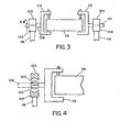
- Figure 1 illustrates a side view of one of two support structures 32 of the clamping fixture of the preferred embodiment.
- the base 40 of the support structure 32 is seated on the work surface 30 of the machining tool.
- the work surface 30 is illustrated in Figure 1 as parallel rails, but may also be any surface that provides means for mounting a support structure 32. Rails facilitate movement of a cylinder head and clamping fixture in a horizontal plane below the machining tool.
- the support structure 32 may be fastened to the work surface 30 by the use of rail locking screws 48 or other suitable means to prevent the support structure 32 from moving.
- Each support structure 32 has a base assembly 40, columns 52, and a clamp assembly 34. As shown in Figure 1, the base assembly 40 of the preferred embodiment rests upon the work surface 30 and includes the rail locking screws 48. Column channels 36 extend through the base assembly 40 and are sized to accept a first and second column 52.
- the preferred embodiment includes two parallel columns 52, however, alternate embodiments may have more than two columns.
- the columns 52 are attached to the clamp assembly 34 so that an upward or downward movement of the columns 52 will similarly move the clamp assembly 34 upwardly or downwardly.
- the clamp assembly 34 includes an upper block 44 hingedly attached to a lower block 42 at a clamp pivot point 46.
- the upper and lower blocks may be vertically separable along extensions of the columns, or one or both of the blocks may be detachable form the clamp block.
- the hinging of the upper block 44 from the lower block 42 of preferred embodiment provides an unobstructed access to a spherical recessed area 60 of the lower block 42.
- the upper block 44 and lower block 42 of the preferred embodiment have spherical recessed areas 58, 60 which form a spherical opening 38 when the upper block 44 is hinged closed upon the lower block 42.
- the spherical opening 38 provides a seat for a spherical spring collet 62, also referred to herein as a clamp band.
- the spherical spring collet 62 fits onto the arbor 64 of a fastening device that is attachable to an end of a cylinder head.
- FIG. 3 The manner in which a cylinder head is held in position by a pair of support structures 32 is illustrated in Figure 3.
- a first fastening device 114 and a second fastening device 112 are attached to opposing ends of a cylinder head 118.
- the fastening devices 112, 114 include arbors 110, 108 that extend outward from the fastening devices 112, 114.
- the arbors 110, 108 are seated in pillow blocks consisting of upper pillow blocks 100, 104 and lower pillow blocks 102, 106 attached to columns 116.
- the arbor of Figure 3 is freely rotatable as indicated by R, i.e. 360 degrees, in a clockwise or counterclockwise direction when the pillow blocks are not tightened around the arbor.
- a spherical spring collet 120 that may be seated into a spherical recess of the pillow block as shown in Figure 4.
- the spherical spring collet 120 is a sphere-shaped collet that fits onto the arbor 108 and may be formed as a spherical shell with opposing arbor openings or as a sphere with a channel.
- Either embodiment of the spherical spring collet 120 includes slits 122 that alternately extend from one arbor opening towards, but stopping short of, the opposing arbor opening.
- the slits 122 allow the spherical spring collet 120 to contract, and thereby tighten upon the arbor 108 when the upper block 100 is mated and locked to the lower block 102.
- the number of alternating slits 122 may vary according to the size of the spherical spring collet 120 and/or the resilience of the material that forms the collet 120.
- the spherical spring collet 62 must be slightly larger in diameter than the inside diameter of the spherical opening 38 that is formed when the spherical recessed area of the upper block 44 is mated to the spherical recessed area 60 of the lower block 42.
- the upper block 44 must be locked in place to the lower block 42 by a locking mechanism 54.
- the preferred embodiment utilizes a lever locking mechanism 54 that provides a locking pressure that forces the upper block 44 towards the lower block 42.
- the locking mechanism 54 pivots on a locking mechanism pivot 56 to release the spherical spring collet 62 from a contracted state and to allow the upper block 44 to hinge open from the lower block 42 on clamp pivot 46.
- Other embodiments may utilize variations of the mechanical clamp locks as illustrated by the locking mechanism 14 in Figure 6.
- the upper and lower blocks 44,42 may also utilize pneumatic, hydraulic, or electrical locking assemblies.
- the spherical spring collet 62 of the preferred embodiment is shown to accept a cylindrical arbor 64. As shown in Figures 3 and 4, rotation of the cylinder head 118 is facilitated by the spherical spring collet 120 rather than by the shape of the arbor 108.
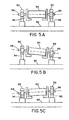
- Figures 5a through 5c illustrate the further advantages of a spherical spring collet.
- spherical spring collets 86 also allow a cylinder head 84 to be tilted lengthwise.
- Figure 5a illustrates a cylinder head 84 suspended between pillow blocks 80 and 82.
- Columns 94 and 92 are equally extended to maintain the cylinder head 84 in a plane that is parallel to work surface 90.
- column 94 is extended upward to lift a first end of the cylinder head 84. As the column is raised, the spherical spring collets 86 turn within the spherical openings of the pillow blocks 80,82.
- Figure 5c illustrates column 94 in a nearly un-extended position that causes a second end of the cylinder head 84 to be raised above the first end.
- the columns 94 and 92 can be raised or lowered simultaneously or separately.
- Figures 5a-5c illustrate the forward columns 94,92 of a two column support structure with the second columns hidden from view behind the forward columns 94,92.
- Figures 5a-5c may also be considered to illustrate a side view of an second embodiment that includes singular column support structures 94,92.
- columns 52 of the support structure 32 may extend upward to an extended height that is determined by the column length and the extension limit of the upward biasing component(s) of the structure 32.
- Figure 1 illustrates the columns 52 in an un-extended position.
- the upward biasing components of the preferred embodiment are gas struts 66.
- the gas struts 66 When the columns 52 are in an unlocked state, the gas struts 66 will lift the pillow block 34 and the corresponding end of the supported cylinder head to a full extension which is dependent upon the length of the extended gas strut 66.
- the cylinder head is lowered by exerting a downward pressure on the cylinder head. The downward pressure overcomes the upward bias of the gas struts 66 and causes the columns 52 to slide downward into the column channels 36.
- the columns 52 are locked into place utilizing a column locking mechanism thereby locking and preserving the desired cylinder head height.
- the height may be adjusted by releasing the column locking mechanism, thus allowing the upward bias to exert an upward force.
- the operator then reapplies a downward pressure by pushing down on the cylinder head until the alternate desired height is achieved.
- the column locking mechanism of the preferred embodiment is illustrated in Figure 1.
- Spring collets 68 are position concentrically with the column channels 36 and adjacent a top surface 41 of the base assembly 40. Collet plate 50 squeezes and presses the collets 68 into the columns 52 thereby locking the columns 52 into a desired position.
- the locked position of the preferred embodiment is the normal, or "at rest, " state of the clamping fixture.
- air is introduced into air inlet 70 to activate piston 72.
- Piston 72 lifts the collet plate 50 allowing the spring collets 68 to expand and release the columns 52.
- air pressure into the piston 72 is removed and the collet plate 50 lowers and re-exerts an inward pressure on the spring collets 68 which then hold the columns 52 at their desired height position.
- the collet plate 50 may be lifted to release the columns 52 by hydraulics, electrical or mechanical assemblies, or a variation of the above described pneumatic system. Also, it is not necessary to use a spring collet-based locking system.
- the columns may be locked by a gearing system or by any equivalent mechanical, hydraulic, pneumatic, or electrical system which can be configured to lock and release the columns 52.
- the engine cylinder head 84 may be tilted lengthwise. Tilting the cylinder head requires independent operation of the columns 94 and 92.
- the pneumatic system controls the pistons 72 of the first and second support structures 32 that support the opposing ends of the cylinder head.
- a stop pin 76 as shown in Figure 1 may be utilized.
- Figure 2 illustrates a cross section of a column 52 of the clamping fixture. Stop pin 76 extends from the base 40 and may be pulled outward to release the stop pin 76 from a column recess 77.
- the column recess 77 aligns with the stop pin 76 when the column 52 is in an un-extended position.
- the pneumatic assembly lifts the collet plates 50 of the first and second support structures 32
- the upward bias of the gas struts 66 cannot lift the pillow blocks 34 unless the stop pins 76 have been released.
- a lengthwise tilt of the cylinder head as shown in Figures 5a-5c can be accomplished by releasing a single stop pin 76 of either the first or second support structures 32.
- columns 140 are pivotally attached to the pillow block 142 at pivotal attachment points 144 to allow independent operation of the columns 140.
- a single corner of the cylinder head can be lowered to provide a lengthwise and sideways tilt of the cylinder head after the desired rotational angle has been chosen. Downward pressure in one corner of the cylinder head or pillow block 142 will cause a column 140 nearest the pressure to lower.
- the embodiment with sideways tilt provides a fine adjustment of the rotational angle once the arbors have been locked into position by a clamping block locking mechanism.
- FIG. 1 An optional clamping fixture handle 78 is illustrated in Figure 1 and in Figure 2 of the preferred embodiment.
- the handle 78 allows an operator to grip each support structure 32 for a number of purposes including for moving the clamping fixture horizontally on the work surface 30.
- horizontal movement of the clamping fixture may be facilitated by an mechanical, electrical, pneumatic, or hydraulic moving mechanism that is integral to the work surface.
- Figure 6 is a perspective drawing of an alternate embodiment of a support structure 2.
- a base 4 is seated on parallel rails of a work surface 30 of a machining apparatus.
- Columns 22 may be raised and lowered into column channels 26 in the base 4 when a locking mechanism assembly 28 is lifted off of the base 4 to release the columns 22 from a locked position.
- a pillow block assembly is attached to columns 22 and consists of an upper block 8 that is hingedly connected at a hinge point 18 to a lower block 6.
- Upper and lower blocks 8,6 include spherical recessed areas 16,20 that form a spherical opening when the upper and lower blocks 8,6 are hinged into a closed position.
- the spherical opening accepts a clamp band 10 that may be sized to be minimally larger that the spherical opening.
- a clamp band 10 that may be sized to be minimally larger that the spherical opening.
- Figure 7 illustrates a side view of a mechanical means for lowering at least one column 52 of the clamping fixture.
- the upward bias of the support structure may be difficult to overcome when a workpiece is not supported on the clamping assembly. Therefore, an alternative means to lower a column 52 may be desirable.
- Figure 7 illustrates an exemplary means that utilizes a mechanical gearing assembly.
- An operator wheel l90 rotates gear wheel l94 that interacts with rack gear l92 to lower column 52.
- the rack gear l92 may be machined onto or attached to the outside of column 52.
- the mechanical gearing assembly illustrated in Figure 7 is a downward bias mechanism.
- a downward bias may also be accomplished by other systems which are known in the art, including electrical, pneumatic, or hydraulic systems.
- the present invention uses a spherical joint/ball positioned inside a spherical pillow block that is attached to a vertically slidable column.
- the spherical ball/joint provides the clamping fixture with a capability to rotate and tilt an attached cylinder head.
- Figure 9 illustrates a non-split pillow block 132 that does not open to accept an arbor assembly 130.
- the spherical spring collet 136 is integral to the pillow block and the arbor assembly 130 is slidable into the collet.
- a gap 134 in the pillow block 132 allows the collet 136 to expand to an unlocked state. Locking the pillow block 132 involves tightening the gap 134 and thereby contracting the collet 136.
- a spherical collet is integral to the fastening device which is fastened to the cylinder head.
- the opening of the pillow block that accepts the spherical collet need only be a partial spherical recess. Additionally, the arbor need not extend through either the collet or the pillow block.
- Parallelizing refers to a time-saving process of preparing any number of cylinder heads for machining.
- the present invention provides a means to prepare cylinder heads for serial insertion into a clamping fixture while the machining device is being utilized.
- the cylinder head and fastening devices form a palletable unit that may be prepared apart from the clamping fixture and later transferred to the clamping fixture as required.
Landscapes
- Engineering & Computer Science (AREA)
- Mechanical Engineering (AREA)
- Jigs For Machine Tools (AREA)
- Forklifts And Lifting Vehicles (AREA)
- Pivots And Pivotal Connections (AREA)
- Body Structure For Vehicles (AREA)
- Vehicle Body Suspensions (AREA)
- Pressure Welding/Diffusion-Bonding (AREA)
- Machine Tool Units (AREA)
Claims (17)
- Spannvorrichtung für einen Motorzylinderkopf (84; 118) auf einer Arbeitsoberfläche (30; 90) in Vorbereitung auf die Bearbeitung, wobei die Spannvorrichtung aufweist:eine Befestigungseinrichtung (112; 114; 130), die eine davon ausgehende zylindrische Spindel (64; 108, 110) hat, um jedes Ende des Motorzylinderkopfs einzuspannen,ein Paar Trägerstrukturen (2; 32), die beweglich auf der Arbeitsoberfläche (30; 90) angebracht sind, um Bewegung in einer horizontalen Ebene zu ermöglichen, wobei jede Trägerstruktur (2; 32) aufweist:einen Basisaufbau (4; 40), der wenigstens einen vertikalen, hindurchverlaufenden Kanal (26; 36) hat,eine Säule (22; 52; 116), die gleitfähig in jedem Kanal (26; 36) angeordnet ist,Mittel (24; 66; 90, 92, 94) zum Einstellen einer Höhe der Säule relativ zu dem Basisaufbau,Säulenfeststellmittel (50, 68) zum Feststellen der Säulen (22; 52; 116) in einer gewünschten Höhe relativ zu dem Basisaufbau (4; 40),einen Spannaufbau (34; 80, 82; 132, 134, 136), der an einem oberen Bereich der Säulen (22; 52; 116) befestigt ist, dadurch gekennzeichnet, dass der Spannaufbau einen Lagersitz (34; 42, 44; 80, 82; 100, 102, 104, 106; 132; 142) aufweist, der eine darin gebildete Spindelöffnung (38) hat, um die zylindrische Spindel (64; 108, 110) aufzunehmen, wobei der Lagersitz (34; 42, 44; 80, 82; 100, 102, 104, 106; 132; 142) dazu angepasst ist, um ein Kippen der Spindel (64; 108, 110) auf eine gewünschte Neigung relativ zu der Arbeitsoberfläche (30; 90) zu erlauben und um eine Drehung der Spindel (64; 108, 110) auf eine gewünschte Drehung zu ermöglichen, undeine Spindelfeststelleinrichtung (10; 62; 86; 122; 136) zum Feststellen der Spindel (64; 108, 110) innerhalb der Spindelöffnung (38) bei der gewünschten Neigung und Verdrehung,und wobei jeder Basisaufbau (4; 40) zwei vertikale, hindurchverlaufende Kanäle (26; 36) hat.
- Spannvorrichtung nach Anspruch 1, weiter dadurch gekennzeichnet, dass die Spindelfeststelleinrichtung (10; 62; 86; 122; 136) ein Spannband aufweist, das in der Spindelöffnung (38) in dem Lagersitz (34; 42, 44; 80, 82; 100, 102, 104, 106; 132; 142) so angeordnet ist, dass es die Spindel (64; 108; 110) umfasst, wobei das Klemmband dazu angepasst ist, sich um die Spindel zusammenzuziehen, um die Spindel bei der gewünschten Verdrehung festzustellen.
- Spannvorrichtung nach Anspruch 2, weiter dadurch gekennzeichnet, dass das Spannband eine sphärische Spannhülse ist und die Spindelöffnung (38) wenigstens teilweise sphärisch ist.
- Spannvorrichtung nach Anspruch 2 oder 3, weiter dadurch gekennzeichnet, dass das Spannband (10; 62; 86; 122; 136) radial zum Zusammenziehen gebracht wird, indem der Lagersitz zusammengezogen wird.
- Spannvorrichtung nach einem der Ansprüche 1 bis 4, weiter dadurch gekennzeichnet, dass die Säulenfeststellmittel (50, 68) pneumatisch oder hydraulisch gesteuert sind.
- Spannvorrichtung nach einem der Ansprüche 1 bis 5, weiter dadurch gekennzeichnet, dass die Säulenfeststellmittel (50, 68) ein Spannband (68) aufweisen, das dazu angepasst ist, sich um die Säulen (22; 52; 116) auszudehnen und zusammenzuziehen.
- Spannvorrichtung nach Anspruch 6, weiter dadurch gekennzeichnet, dass das Spannband (68) eine Spannhülse ist und die Spannhülse durch eine pneumatisch gesteuerte Platte (50) geschlossen wird, die Druck ausübt, um die Spannhülse zusammenzuhiehen.
- Spannvorrichtung nach einem der Ansprüche 1 bis 7, weiter dadurch gekennzeichnet, dass die Höheneinstellmittel (24; 66; 90, 92, 94) einen nach oben wirkenden Vorspannmechanismus (24; 66) umfassen.
- Spannvorrichtung nach einem der Ansprüche 1 bis 8, weiter dadurch gekennzeichnet, dass die Höheneinstellmittel (24; 66; 90, 92, 94) einen mechanischen Getriebeaufbau (190, 192, 194) umfassen.
- Spannvorrichtung nach einem der Ansprüche 1 bis 9, weiter dadurch gekennzeichnet, dass die Säulenfeststellmittel (50; 68) für die beiden Trägerstrukturen (2; 32) funktionsmäßig verbunden sind.
- Verfahren zum Einspannen eines Motorzylinderkopfs (84; 118) in Vorbereitung auf die Bearbeitung, mit den Schritten:Anbringen einer Befestigungseinrichtung (112, 114; 130) an jedes Ende des Zylinderkopfs (84; 118), wobei die Befestigungseinrichtung eine zylindrische Spindel (64; 108, 110) hat, die davon ausgehend so verläuft, dass eine Spindel (64; 108, 110) von jedem Ende des Motorzylinderkopfs ausgeht,Bewegen eines Paars von Trägerstrukturen (2; 32) auf einer Arbeitsoberfläche (30; 90), so dass eine Trägerstruktur nahe an jedem Ende des Zylinderkopfs (84; 118) positioniert ist, wobei jede Trägerstruktur (2; 32) einen Basisaufbau (4; 40) mit zwei vertikal hindurchverlaufenden Kanälen (26; 36), eine Säule (22; 52; 116), die gleitfähig in jedem Kanal (26; 36) angeordnet ist, Höheneinstellmittel (24; 66; 90, 92, 94) zum Einstellen einer Höhe der Säule (22; 52; 116) relativ zu dem Basisaufbau (4; 40), Säulenfeststellmittel (50, 68) zum Feststellen der Säulen bei einer bestimmten Höhe innerhalb des wenigstens einen Kanals (26; 36), einen Einspannaufbau (34; 80, 82; 132, 134, 136), der an einem oberen Bereich der Säulen (22; 52; 116) angebracht ist, aufweist, wobei der Einspannaufbau (34; 80, 82; 132, 134, 136) einen Lagersitz (34; 42, 44; 80, 82; 100, 102, 104, 106; 132; 142) mit einer darin gebildeten Spindelöffnung (38) zur Aufnahme der Spindel (64; 108, 110), wobei der Lagersitz (34; 42, 44; 80, 82; 100, 102, 104, 106; 132; 142) dazu angepasst ist, das Kippen der Spindel (64; 108, 110) auf eine gewünschte Neigung relativ zu der Arbeitsoberfläche (30; 90) und die Drehung auf eine gewünschte Verdrehung zu erlauben, und eine Spindelfeststelleinrichtung (10; 62; 86; 122; 136) zum Feststellen der Spindel (64; 108, 110) innerhalb der Spindelöffnung (38) bei der gewünschten Verdrehung und Neigung aufweist;Einsetzen jeder Spindel (64; 108, 110) in die Spindelöffnung (38) der nächsten Trägerstruktur (2; 32),Drehen des Motorzylinderkopfs (84; 118) auf die gewünschte Verdrehung,gleichzeitig Einstellen der Höhe der Säulen (22; 52; 116) in wenigstens einer der Trägerstrukturen (2; 32) und Kippen der Spindel (64; 108, 110) innerhalb der Spindelöffnung, um den Motorzylinderkopf (84; 118) auf die gewünschte Neigung zu kippen, indem die Säulen (22; 52; 116) innerhalb des Kanals (26; 36) des jeweiligen Basisaufbau (4; 40) vertikal verschoben werden,Feststellen der Spindelfeststelleinrichtungen (10; 62; 86; 122; 136) der entsprechenden Trägerstruktur (2; 32) um jede der Spindeln (64; 108, 110), um den Motorzylinderkopf (84; 118) bei der gewünschten Verdrehung festzustellen, undFeststellen der Höhe der Säulen (22; 52; 116) in jeder der Trägerstrukturen (2; 32), um den Motorzylinderkopf (84; 118) bei der gewünschten Neigung festzustellen.
- Verfahren nach Anspruch 11, weiter dadurch gekennzeichnet, dass der Schritt des Feststellens der Spindelfeststelleinrichtungen (10; 62; 86; 122; 136) das Zusammenziehen eines Spannbands um jede der Spindeln (64; 108, 110) umfasst.
- Verfahren nach Anspruch 12, weiter dadurch gekennzeichnet, dass das Spannband (10; 62; 86; 122; 136) eine sphärische Spannhülse ist und dass die Spindelöffnung (38) wenigstens teilweise sphärisch ist.
- Verfahren nach Anspruch 13, weiter dadurch gekennzeichnet, dass vor oder nach dem Schritt der Anbringung der Befestigungseinrichtung (112, 114; 130) die sphärische Spannhülse um jede der Spindeln (64; 108, 110) platziert wird.
- Verfahren nach einem der Ansprüche 11 bis 14, weiter dadurch gekennzeichnet, dass die Säulenfeststellmittel (50, 68) ein Spannband (68) aufweisen und der Schritt des Feststellens der Höhe das Zusammenziehen des Spannbands (68) um die Säulen (22; 42; 116) umfasst.
- Verfahren nach einem der Ansprüche 11 bis 15, weiter dadurch gekennzeichnet, dass die Säulenfeststellmittel (50, 68) hydraulisch oder pneumatisch gesteuert werden.
- Verfahren nach einem der Ansprüche 11 bis 16, weiter dadurch gekennzeichnet, dass die Säulenfeststellmittel (50; 68) für beide Trägerstrukturen (2; 32) funktionsmäßig verbunden sind.
Applications Claiming Priority (5)
| Application Number | Priority Date | Filing Date | Title |
|---|---|---|---|
| US8724298P | 1998-05-29 | 1998-05-29 | |
| US87242P | 1998-05-29 | ||
| US09/153,765 US6113322A (en) | 1998-05-29 | 1998-09-15 | Cylinder head clamping fixture |
| US153765 | 1998-09-15 | ||
| PCT/US1999/008692 WO1999062670A1 (en) | 1998-05-29 | 1999-04-21 | Cylinder head clamping fixture |
Publications (2)
| Publication Number | Publication Date |
|---|---|
| EP1082192A1 EP1082192A1 (de) | 2001-03-14 |
| EP1082192B1 true EP1082192B1 (de) | 2004-06-16 |
Family
ID=26776761
Family Applications (1)
| Application Number | Title | Priority Date | Filing Date |
|---|---|---|---|
| EP99917641A Expired - Lifetime EP1082192B1 (de) | 1998-05-29 | 1999-04-21 | Spannvorrichtung für zylinderköpfe |
Country Status (6)
| Country | Link |
|---|---|
| US (1) | US6113322A (de) |
| EP (1) | EP1082192B1 (de) |
| AT (1) | ATE269187T1 (de) |
| AU (1) | AU3571299A (de) |
| DE (1) | DE69918106T2 (de) |
| WO (1) | WO1999062670A1 (de) |
Families Citing this family (20)
| Publication number | Priority date | Publication date | Assignee | Title |
|---|---|---|---|---|
| JP2001079018A (ja) * | 1999-09-14 | 2001-03-27 | Gc Corp | 歯科用自動切削加工装置 |
| CN103707088A (zh) * | 2013-12-24 | 2014-04-09 | 安徽新源石油化工技术开发有限公司 | 一种管件坡口机可调夹具 |
| CN105081388A (zh) * | 2015-07-14 | 2015-11-25 | 成都力鑫科技有限公司 | 一种用于钻孔的可调机械工装 |
| US10189535B1 (en) | 2016-10-12 | 2019-01-29 | Arnott T&P Holding, Llc | Motorcycle display unit system and method |
| CN107470945A (zh) * | 2017-09-29 | 2017-12-15 | 如皋市祥强机械设备有限公司 | 一种模具加工用的支撑装置 |
| DE102018100708B4 (de) * | 2018-01-15 | 2021-01-28 | Schwer Fittings Gmbh | Spannbackenanordnung, System umfassend eine solche Spannbackenanordnung sowie Verfahren zur Fixierung eines Bauteils |
| CN108994333A (zh) * | 2018-06-28 | 2018-12-14 | 湖州天骊正隆电子科技有限公司 | 一种用于打印机零部件加工的防偏钻孔设备 |
| CN109202476A (zh) * | 2018-10-24 | 2019-01-15 | 天台县银兴机械铸造有限公司 | 一种可调节角度的机床夹具 |
| CN110142615B (zh) * | 2019-05-28 | 2024-10-01 | 南京信息职业技术学院 | 相邻孔钻孔的工件固定工装 |
| CN110405680A (zh) * | 2019-07-23 | 2019-11-05 | 广州市富鑫机械设备有限公司 | 一种用于发动机缸体的夹具 |
| CN110280512B (zh) * | 2019-08-03 | 2021-09-03 | 海南华星包装印刷有限公司 | 一种油墨印刷辊自动化清洗装置及方法 |
| CN112454194B (zh) * | 2020-10-30 | 2024-04-09 | 广西玉柴机器股份有限公司 | 一种兼容不同气缸盖加工底面夹具 |
| CN113695940B (zh) * | 2021-07-15 | 2022-12-16 | 台州永安转向器有限公司 | 一种阀套钢球孔铰珩加工夹具 |
| CN116851810A (zh) * | 2023-06-13 | 2023-10-10 | 中船动力镇江有限公司 | 船用柴油机气缸盖孔系加工工装 |
| CN117943590B (zh) * | 2024-02-02 | 2024-07-05 | 奥利申自动门(山东)有限公司 | 一种电动伸缩门加工钻孔定位装置 |
| CN117884683B (zh) * | 2024-03-18 | 2024-06-21 | 山西汉通鑫宇科技股份有限公司 | 一种轴承盖快速装夹钻孔定位夹具 |
| CN118700056B (zh) * | 2024-08-28 | 2024-11-15 | 锦湖轮胎(天津)有限公司 | 一种在轮胎试验机上便于轴杆固定的快速夹具 |
| CN119164550B (zh) * | 2024-11-20 | 2025-04-04 | 芜湖永达科技有限公司 | 一种缸盖快速水试夹具 |
| CN119175582B (zh) * | 2024-11-25 | 2025-05-09 | 太原市新明机械股份有限公司 | 一种用于注塑机缸套的夹紧工装及其使用方法 |
| CN119683516B (zh) * | 2024-12-17 | 2026-03-10 | 西安航天动力研究所 | 一种齿条定位的重载同步升降和翻转装置及其控制方法 |
Family Cites Families (20)
| Publication number | Priority date | Publication date | Assignee | Title |
|---|---|---|---|---|
| US3782847A (en) * | 1971-12-29 | 1974-01-01 | L Kulzer | Method and apparatus for reconditioning cylinder heads |
| US4140306A (en) * | 1977-10-17 | 1979-02-20 | Head Engineering, Inc. | Fixture for mounting an article to be worked on |
| US4145006A (en) * | 1977-11-11 | 1979-03-20 | Webb William E | Work piece mounting stand |
| US4168826A (en) * | 1978-08-25 | 1979-09-25 | Rottler Boring Bar Co. | Fixture for holding v-type engine blocks |
| IT1201518B (it) * | 1979-09-06 | 1989-02-02 | Ferdinando Cammi | Apparecchiatura da banco particolarmente per operare su pompe di iniezione di motori tipo diesel |
| US4414723A (en) * | 1979-11-15 | 1983-11-15 | K-Line Industries, Inc. | Adjustable cylinder head holder |
| US4417376A (en) * | 1979-11-15 | 1983-11-29 | K-Line Industries, Inc. | Adjustable cylinder head holder |
| US4416570A (en) * | 1980-05-14 | 1983-11-22 | Argenbright Carl T | Precision work holder for machine tools |
| US4657446A (en) * | 1983-02-28 | 1987-04-14 | Sunnen Products Company | Boring machine for cam shaft bearings |
| CH674888A5 (de) * | 1987-07-21 | 1990-07-31 | Minelli Ag | |
| CH682097A5 (de) * | 1990-09-04 | 1993-07-15 | Minelli Ag | |
| US5281057A (en) * | 1992-04-14 | 1994-01-25 | K-Line Industries, Inc. | Valve guide boring fixture |
| US5269501A (en) * | 1992-12-03 | 1993-12-14 | Hein-Werner Corporation | Vehicle and vehicle parts transportation system |
| CA2128075A1 (en) * | 1993-07-15 | 1995-01-16 | Robert L. Aldredge | Clamp structure |
| EP0724496A4 (de) * | 1993-10-19 | 1997-01-15 | Steven Edward Goostrey | Elektropneumatische bearbeitungsvorrichtung |
| JP2954484B2 (ja) * | 1994-06-02 | 1999-09-27 | 川崎重工業株式会社 | シリンダヘッドの組立用パレット |
| US5655278A (en) * | 1994-09-06 | 1997-08-12 | Harmand; Brice | Apparatus and method for boring overhead cam engine cylinder heads |
| US5575488A (en) * | 1995-03-10 | 1996-11-19 | Srw Associates, Inc. | Hand-held part holder and fixture |
| US5759140A (en) * | 1995-04-19 | 1998-06-02 | Ingersoll Cm Systems, Inc. | Method and apparatus for machining holes in crankshafts |
| US5961107A (en) * | 1996-03-06 | 1999-10-05 | Morghen; Manfred A. | Workpiece indexing and clamping system |
-
1998
- 1998-09-15 US US09/153,765 patent/US6113322A/en not_active Expired - Lifetime
-
1999
- 1999-04-21 AU AU35712/99A patent/AU3571299A/en not_active Abandoned
- 1999-04-21 EP EP99917641A patent/EP1082192B1/de not_active Expired - Lifetime
- 1999-04-21 DE DE69918106T patent/DE69918106T2/de not_active Expired - Lifetime
- 1999-04-21 WO PCT/US1999/008692 patent/WO1999062670A1/en not_active Ceased
- 1999-04-21 AT AT99917641T patent/ATE269187T1/de not_active IP Right Cessation
Also Published As
| Publication number | Publication date |
|---|---|
| DE69918106T2 (de) | 2005-07-07 |
| EP1082192A1 (de) | 2001-03-14 |
| WO1999062670A9 (en) | 2000-04-27 |
| WO1999062670A1 (en) | 1999-12-09 |
| US6113322A (en) | 2000-09-05 |
| ATE269187T1 (de) | 2004-07-15 |
| AU3571299A (en) | 1999-12-20 |
| DE69918106D1 (de) | 2004-07-22 |
Similar Documents
| Publication | Publication Date | Title |
|---|---|---|
| EP1082192B1 (de) | Spannvorrichtung für zylinderköpfe | |
| US6560890B1 (en) | Fixture for locating and clamping a part for laser drilling | |
| RU1838090C (ru) | Устройство дл шлифовани инструмента | |
| CA2715779C (en) | Method and fixture for handling and processing die components | |
| US4585217A (en) | Workpiece support apparatus and method | |
| US4140307A (en) | Vices | |
| US9545704B2 (en) | Through cutting mill steady rest | |
| EP0654324A2 (de) | In Stellung und Winkel einstellbarer Schraubstock | |
| EP3257622B1 (de) | Halterung zum halten eines teils während eines bearbeitungsvorgangs | |
| WO1998009759A1 (en) | Apparatus and method for machining valve seats in an engine cylinder head | |
| US5681033A (en) | Workpiece pick-up jig and positioning tool | |
| US5163664A (en) | Alignment tool for machine vise and the like | |
| JPH11226831A (ja) | 板材加工装置のワーククランプ装置 | |
| EP0100421A2 (de) | Bohrständer | |
| US5234295A (en) | Adjustable support fixture | |
| US4318293A (en) | Method for power clamping work pieces | |
| US4127942A (en) | Method and apparatus for reconditioning cylinder heads | |
| US6082234A (en) | Adjustable toolholder | |
| CN220574774U (zh) | 一种新型机床卡盘卡爪 | |
| US4860497A (en) | Drill grinder having drill holder including chucks for gripping shank and body of the drill | |
| US6568237B1 (en) | Apparatus and method for vehicle manipulative anchoring | |
| US4417376A (en) | Adjustable cylinder head holder | |
| JPS59500555A (ja) | 所定位置に物体を堅固に保持する調整可能なクランプ装置 | |
| US4414723A (en) | Adjustable cylinder head holder | |
| US20210394324A1 (en) | Load lifting device and method of lifting load |
Legal Events
| Date | Code | Title | Description |
|---|---|---|---|
| PUAI | Public reference made under article 153(3) epc to a published international application that has entered the european phase |
Free format text: ORIGINAL CODE: 0009012 |
|
| 17P | Request for examination filed |
Effective date: 20001221 |
|
| AK | Designated contracting states |
Kind code of ref document: A1 Designated state(s): AT BE CH CY DE DK ES FI FR GB GR IE IT LI LU MC NL PT SE |
|
| EL | Fr: translation of claims filed | ||
| 17Q | First examination report despatched |
Effective date: 20020307 |
|
| GRAH | Despatch of communication of intention to grant a patent |
Free format text: ORIGINAL CODE: EPIDOS IGRA |
|
| GRAS | Grant fee paid |
Free format text: ORIGINAL CODE: EPIDOSNIGR3 |
|
| GRAA | (expected) grant |
Free format text: ORIGINAL CODE: 0009210 |
|
| AK | Designated contracting states |
Kind code of ref document: B1 Designated state(s): AT BE CH CY DE DK ES FI FR GB GR IE IT LI LU MC NL PT SE |
|
| PG25 | Lapsed in a contracting state [announced via postgrant information from national office to epo] |
Ref country code: NL Free format text: LAPSE BECAUSE OF FAILURE TO SUBMIT A TRANSLATION OF THE DESCRIPTION OR TO PAY THE FEE WITHIN THE PRESCRIBED TIME-LIMIT Effective date: 20040616 Ref country code: LI Free format text: LAPSE BECAUSE OF FAILURE TO SUBMIT A TRANSLATION OF THE DESCRIPTION OR TO PAY THE FEE WITHIN THE PRESCRIBED TIME-LIMIT Effective date: 20040616 Ref country code: IT Free format text: LAPSE BECAUSE OF FAILURE TO SUBMIT A TRANSLATION OF THE DESCRIPTION OR TO PAY THE FEE WITHIN THE PRESCRIBED TIME-LIMIT;WARNING: LAPSES OF ITALIAN PATENTS WITH EFFECTIVE DATE BEFORE 2007 MAY HAVE OCCURRED AT ANY TIME BEFORE 2007. THE CORRECT EFFECTIVE DATE MAY BE DIFFERENT FROM THE ONE RECORDED. Effective date: 20040616 Ref country code: FI Free format text: LAPSE BECAUSE OF FAILURE TO SUBMIT A TRANSLATION OF THE DESCRIPTION OR TO PAY THE FEE WITHIN THE PRESCRIBED TIME-LIMIT Effective date: 20040616 Ref country code: CH Free format text: LAPSE BECAUSE OF FAILURE TO SUBMIT A TRANSLATION OF THE DESCRIPTION OR TO PAY THE FEE WITHIN THE PRESCRIBED TIME-LIMIT Effective date: 20040616 Ref country code: BE Free format text: LAPSE BECAUSE OF FAILURE TO SUBMIT A TRANSLATION OF THE DESCRIPTION OR TO PAY THE FEE WITHIN THE PRESCRIBED TIME-LIMIT Effective date: 20040616 Ref country code: AT Free format text: LAPSE BECAUSE OF FAILURE TO SUBMIT A TRANSLATION OF THE DESCRIPTION OR TO PAY THE FEE WITHIN THE PRESCRIBED TIME-LIMIT Effective date: 20040616 |
|
| REG | Reference to a national code |
Ref country code: GB Ref legal event code: FG4D |
|
| REG | Reference to a national code |
Ref country code: CH Ref legal event code: EP |
|
| REF | Corresponds to: |
Ref document number: 69918106 Country of ref document: DE Date of ref document: 20040722 Kind code of ref document: P |
|
| REG | Reference to a national code |
Ref country code: IE Ref legal event code: FG4D |
|
| PG25 | Lapsed in a contracting state [announced via postgrant information from national office to epo] |
Ref country code: SE Free format text: LAPSE BECAUSE OF FAILURE TO SUBMIT A TRANSLATION OF THE DESCRIPTION OR TO PAY THE FEE WITHIN THE PRESCRIBED TIME-LIMIT Effective date: 20040916 Ref country code: GR Free format text: LAPSE BECAUSE OF FAILURE TO SUBMIT A TRANSLATION OF THE DESCRIPTION OR TO PAY THE FEE WITHIN THE PRESCRIBED TIME-LIMIT Effective date: 20040916 Ref country code: DK Free format text: LAPSE BECAUSE OF FAILURE TO SUBMIT A TRANSLATION OF THE DESCRIPTION OR TO PAY THE FEE WITHIN THE PRESCRIBED TIME-LIMIT Effective date: 20040916 |
|
| PG25 | Lapsed in a contracting state [announced via postgrant information from national office to epo] |
Ref country code: ES Free format text: LAPSE BECAUSE OF FAILURE TO SUBMIT A TRANSLATION OF THE DESCRIPTION OR TO PAY THE FEE WITHIN THE PRESCRIBED TIME-LIMIT Effective date: 20040927 |
|
| NLV1 | Nl: lapsed or annulled due to failure to fulfill the requirements of art. 29p and 29m of the patents act | ||
| REG | Reference to a national code |
Ref country code: CH Ref legal event code: PL |
|
| ET | Fr: translation filed | ||
| PG25 | Lapsed in a contracting state [announced via postgrant information from national office to epo] |
Ref country code: LU Free format text: LAPSE BECAUSE OF NON-PAYMENT OF DUE FEES Effective date: 20050421 Ref country code: IE Free format text: LAPSE BECAUSE OF NON-PAYMENT OF DUE FEES Effective date: 20050421 Ref country code: GB Free format text: LAPSE BECAUSE OF NON-PAYMENT OF DUE FEES Effective date: 20050421 Ref country code: CY Free format text: LAPSE BECAUSE OF FAILURE TO SUBMIT A TRANSLATION OF THE DESCRIPTION OR TO PAY THE FEE WITHIN THE PRESCRIBED TIME-LIMIT Effective date: 20050421 |
|
| PLBE | No opposition filed within time limit |
Free format text: ORIGINAL CODE: 0009261 |
|
| STAA | Information on the status of an ep patent application or granted ep patent |
Free format text: STATUS: NO OPPOSITION FILED WITHIN TIME LIMIT |
|
| PG25 | Lapsed in a contracting state [announced via postgrant information from national office to epo] |
Ref country code: MC Free format text: LAPSE BECAUSE OF NON-PAYMENT OF DUE FEES Effective date: 20050430 |
|
| 26N | No opposition filed |
Effective date: 20050317 |
|
| GBPC | Gb: european patent ceased through non-payment of renewal fee |
Effective date: 20050421 |
|
| PG25 | Lapsed in a contracting state [announced via postgrant information from national office to epo] |
Ref country code: PT Free format text: LAPSE BECAUSE OF NON-PAYMENT OF DUE FEES Effective date: 20041116 |
|
| REG | Reference to a national code |
Ref country code: FR Ref legal event code: PLFP Year of fee payment: 18 |
|
| REG | Reference to a national code |
Ref country code: FR Ref legal event code: PLFP Year of fee payment: 19 |
|
| REG | Reference to a national code |
Ref country code: FR Ref legal event code: PLFP Year of fee payment: 20 |
|
| PGFP | Annual fee paid to national office [announced via postgrant information from national office to epo] |
Ref country code: DE Payment date: 20180515 Year of fee payment: 20 |
|
| PGFP | Annual fee paid to national office [announced via postgrant information from national office to epo] |
Ref country code: FR Payment date: 20180503 Year of fee payment: 20 |
|
| REG | Reference to a national code |
Ref country code: DE Ref legal event code: R071 Ref document number: 69918106 Country of ref document: DE |