EP1082887A2 - Arrangement pour tourner un outil accouplé à un véhicule, en particulier une charrue réversible - Google Patents
Arrangement pour tourner un outil accouplé à un véhicule, en particulier une charrue réversible Download PDFInfo
- Publication number
- EP1082887A2 EP1082887A2 EP00119154A EP00119154A EP1082887A2 EP 1082887 A2 EP1082887 A2 EP 1082887A2 EP 00119154 A EP00119154 A EP 00119154A EP 00119154 A EP00119154 A EP 00119154A EP 1082887 A2 EP1082887 A2 EP 1082887A2
- Authority
- EP
- European Patent Office
- Prior art keywords
- control
- plow
- control valve
- cylinder
- tractor
- Prior art date
- Legal status (The legal status is an assumption and is not a legal conclusion. Google has not performed a legal analysis and makes no representation as to the accuracy of the status listed.)
- Granted
Links
- 230000002441 reversible effect Effects 0.000 title claims description 35
- 230000007935 neutral effect Effects 0.000 claims abstract 2
- 238000000034 method Methods 0.000 claims description 22
- 230000008569 process Effects 0.000 claims description 22
- 230000033001 locomotion Effects 0.000 claims description 4
- 230000008901 benefit Effects 0.000 claims description 3
- 230000001419 dependent effect Effects 0.000 claims 1
- 230000001105 regulatory effect Effects 0.000 abstract 1
- 238000009412 basement excavation Methods 0.000 description 3
- 238000010276 construction Methods 0.000 description 3
- 230000008878 coupling Effects 0.000 description 3
- 238000010168 coupling process Methods 0.000 description 3
- 238000005859 coupling reaction Methods 0.000 description 3
- 230000007246 mechanism Effects 0.000 description 2
- 230000009286 beneficial effect Effects 0.000 description 1
- 230000000903 blocking effect Effects 0.000 description 1
- 230000008859 change Effects 0.000 description 1
- 238000001514 detection method Methods 0.000 description 1
- 238000011161 development Methods 0.000 description 1
- 230000018109 developmental process Effects 0.000 description 1
- 238000009434 installation Methods 0.000 description 1
- 238000005259 measurement Methods 0.000 description 1
- 238000004091 panning Methods 0.000 description 1
- 238000004886 process control Methods 0.000 description 1
- 230000029305 taxis Effects 0.000 description 1
Images

Classifications
-
- A—HUMAN NECESSITIES
- A01—AGRICULTURE; FORESTRY; ANIMAL HUSBANDRY; HUNTING; TRAPPING; FISHING
- A01B—SOIL WORKING IN AGRICULTURE OR FORESTRY; PARTS, DETAILS, OR ACCESSORIES OF AGRICULTURAL MACHINES OR IMPLEMENTS, IN GENERAL
- A01B3/00—Ploughs with fixed plough-shares
- A01B3/36—Ploughs mounted on tractors
- A01B3/40—Alternating ploughs
- A01B3/42—Turn-wrest ploughs
Definitions
- the invention is based on a device for turning one articulated on an agricultural vehicle Attachment, in particular one attached to a tractor Rotary plow according to the preamble of claim 1 closer specified genus.
- the inventive device for turning one on agricultural vehicle articulated attachment, especially a rotary plow attached to a tractor with the characterizing features of the main claim on the other hand the advantage that with it an actuation of the Turning process on rotary plows with the help of the tractor arranged, electrically controllable control valves possible which are connected to the tractor working hydraulics. Multi-way valves can be used as control valves do not have to have a free position.
- Multi-way valves can be used as control valves do not have to have a free position.
- the device allows a simplified structure the actuation device on the plow side, since on a special, mostly mechanically reversible reversing valve the plow can be dispensed with.
- the number of electrical interfaces between Tractor and plow for sensor or control lines also reduced.
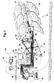
- FIG. 1 shows a simplified representation in Side view of a tractor 10 with a electrohydraulic hoist control device 11, at the a three-point linkage 12 hinged a reversible plow 13 is.
- the hoist control valve 17 controls a hydraulic power lift 19 on one one-armed lifting arm 21 attacks.
- the lifting arm 21 is over a Lift rod 22 with the lower links of the three-point linkage 12 coupled.
- a conventional position sensor is on the lifting arm 21 23 and arranged on the lower link a force sensor 24, the Signals of the control electronics 14 are supplied.
- the reversible plow 13 has a Extension head 25 articulated on the three-point linkage 12.
- the reversible plow 13 can be rotated by 180 degrees in its longitudinal axis it is in the attachment head 25 via an axis of rotation 26 pivoted.
- its longitudinal axis serves as a differential cylinder trained, double-acting turning cylinder 27, the on the one hand attacks on the head 25 and on the other hand on Frame of the reversible plow 13 is attached.
- This Turning cylinder 27 is hydraulic from a first Control valve 28 controlled, which is designed as a 4/3-way valve is and on the tractor side near the hoist control valve 17 is arranged.
- the control valve 28 is thus in the connected hydraulic working group on the tractor 10.
- the rotary plow has three Double plow body 29 in pairs on one swing-out plow frame 31 are attached.
- To the Making the working width adjustable when plowing is on Rotary plow 13 of the plow frame 31 in a manner known per se pivotable via a double-acting actuating cylinder 32 arranged, as is already the case with such Vario rotary plows Is standard.
- the double-acting actuating cylinder 32 is also designed as a differential cylinder and is from controlled a second control valve 33, which is also on the tractor side next to the hoist control valve 17 is arranged and in the tractor-side working hydraulics is switched.
- control valves 28 and 33 for the adjustment functions on the reversible plow 13 are similar valves, each an electro-hydraulic Have control, work with an individual pressure compensator and have a controlled valve spool position so that with them reproducible, balanced valve characteristics are controllable so that regardless of changing Load pressures always proportional to the control Volume flows can be achieved.
- Both control valves 28 and 33 are electrically controllable by the control electronics 14.
- the Reversing cylinder 27, the actuating cylinder 32, the two Control valves 28 and 33 and the control electronics 14 are thus parts of a device 34 which is used to turn the am Tractor 10 attached rotary plow 13 is used.
- this device 34 still has a sensor means that Plow turning the top dead center position of the turning cylinder 27 is detected and implemented here as a pressure sensor 35 is; this pressure sensor 35 is on the tractor 10 side arranged and determined the in the lower annulus 36 of the Reversing cylinder 27 occurring pressure.
- FIG. 2 now shows this device 34 according to the invention for adjusting the reversible plow 13 according to FIG. 1 in one highly simplified, schematic representation in which however, for a better understanding of the tractor 10 as well associated electro-hydraulic hoist control device 11 are omitted. Otherwise, however, the same components provided with the same reference numerals again.
- the first pressure sensor 35 on the first Connection 37 of the first control valve 28 a second Pressure sensor 38 at the second port 39 of the same valve arranged.
- the first connection 41 second control valve 33 for the actuating cylinder 32 a third Pressure sensor 42 and in a corresponding manner on the second Connection 43 a fourth pressure sensor 44 is arranged.
- the Signals of all of these pressure sensors 35, 38, 42, 44 are the Control electronics 14 supplied.
- At the interface 40 between tractor 10 and reversible plow 13 hydraulic lines to the turning cylinder 27 and Actuating cylinder 32 connected by hydraulic couplings 45.
- the tractor 10 In the "plowing" process, the tractor 10 is working on known way with the electro-hydraulic hoist control device 11, the lower plow body of the Rotary plow 13 are guided in the ground so that the Control unit 15 set control type, such as Force, position, mixed control, is carried out. Reached the tractor 10 the end of the field, the rotary plow 13 from the Be lifted and turned before the tractor 10 turns and continues to plow in the opposite direction.
- This multi-stage plow turning process can now be done with the Perform device 34, the tractor side existing control electronics 14 with the tractor side existing, electrically controllable control valves 28 and 33 automatically controls the multi-stage turning process.
- This Plow management for the reversible plow 13 is started, by giving the driver one at the end of the field after plowing Lift switch in the control unit 15 actuated. This will via the hoist control device 11 of the reversible plow 13 in its upper excavation position or transport position dug out.
- the rotary plow 13 has this raised position reached, the control electronics 14 controls the second Control valve 33, the actuating cylinder 32, so that this by a pivoting of the plow frame 31 the plow to a minimum Width adjusted. This pivoting is required to a possible impact of the reversible plow 13 at prevent subsequent turning on the floor.
- the second control valve 33 via its second connection 43 a pressure medium flow to Cylinder chamber of the actuating cylinder 32 controls the Swing in to the minimum width. Reaches the Actuating cylinder 32 the end position for minimum width e.g. can be defined by a mechanical stop, this leads to an increase in pressure in the second connection 43, which is recognized by the fourth pressure sensor 44 and as a signal the control electronics 14 is supplied. This allows the Control electronics 14, the second control valve 33 in its Stand back middle position and the subsequent Initiate the turning process.
- the turning cylinder 27 moves in the in FIG shown position until it is in the shortest position top dead center reached.
- This turning cylinder 27 is part a rotating device that a thrust crank with Reversible cylinder 27 corresponds to an actuator. It is therefore building up a high pressure in the top dead center of the turning cylinder 27 on that as information for achieving this characteristic position is used.
- this dead center position of the hydraulic on both sides acted upon turning cylinder 27 is the first pressure sensor 35 provided near the terminal 37.
- the second Pressure sensor 38 registers an increase in pressure when the end position of the rotary drive due to mechanical Attacks is achieved.
- This information from the pressure sensor 38 uses the control electronics 14 to the first Control valve 28 in its middle blocking position to postpone. This information is also provided by the Completion of the rotational movement used to the Control electronics 14 via the second control valve 33 Actuating cylinder 32 controls so that a pivoting of the Plow frame 31 to its originally set Working width is achieved. Did the plow originally set cutting width is reached again, the Actuating cylinder 32 against a mechanical stop drive, the pressure increase occurring from the third Pressure sensor 42 detected and reported to control electronics 14 becomes. The control electronics 14 can then via the Habtechnik control device 11 the reversible plow 13 in his Lower working position.
- the device 34 for turning the reversible plow 13 can plow management at the end of the field, whereby the tractor-side process control by the Control electronics 14 a largely automatic process which provides functions to be operated at the end of the field.
- This Plow management is only done by the tractor driver through the Actuate the excavation switch in the control panel 15 and by Reaching a defined excavation height of the Three-point linkage 12 started.
- the plow frame 31 is like described swung in, rotated and swung out again.
- the controls receive the position signals of the two differential cylinders from the pressure sensors 35, 38, 42, 44. It is crucial that the switching of the first control valve 28 at the top dead center of the turning cylinder 27 takes place, but not a switch to free is required. Furthermore, the control of the turning process by using pressure increases in blocked Cylinder positions possible, this by mechanical End stops and the top dead center of the turning cylinder 27 are marked.
- the Panning process also through a combined pressure sensor time control performed with high accuracy allows when setting.
- the pressure sensors 42, 44 by additional Use the time period when swiveling the Actuating cylinder 32 to the required time and Control of the control valve 33 when swiveling getting closed. Counts as the length of time when swinging in the duration from the start of the swinging in until Sensing the pressure increase when reaching the pivoted end position.
- the cutting width can also be for a percentage Percentage of the total adjustment time can be set, see above that also intermediate positions between the end positions are controllable. To control these intermediate layers must the percentage of time to reach certain locations once be recorded experimentally.
- each working connection of the two control valves 38, 33 is particularly useful, can also with a single Pressure sensor per control valve 28, 33 can be worked. there the load pressure returned in the control valve is sensed; this is the inside of the valve on the individual pressure compensator returned load pressure.
- the logical assignment to each The relevant working connection of the control valve is made internally via the control electronics 14 together with the Knowledge of the control direction of the control valves 28, 33.
- each control valve 28 or 33 a single Assign pressure sensor that via additional shuttle valves to the two working connections 37, 39 and 41, 43 is connected so that the higher pressure is measured becomes.
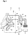
- FIG 3 shows a highly simplified, schematic Representation of a second embodiment of a device 50 according to the invention for turning one over Tractor mounted reversible plow, with the same components as in Figure 2 also provided with the same reference numerals are.
- the second device 50 differs from that first device 34 according to Figure 2 mainly in that them as sensor means for detecting the upper one Dead center position in the turning cylinder 27 an angle sensor 51 used, which is mechanically coupled to the axis of rotation 26 is.
- the electromechanical angle sensor 51 is via a Signal line 52 connected to the control electronics 14.
- the hydraulic couplings 55 there is an additional one electrical plug-in coupling 53 required.
- the two around 180 Degree rotated end positions of the reversible plow 13 are now through Stops 54 and 55 marked.
- the first control valve 28 is shown here simply as a 4/3-way valve, which next to a spring-centered locking position 56 two Has working positions 57 and 58.
- the mode of operation of the second device 50 corresponds to FIG Regarding the turning process of the reversible plow 13 of the Operation of the first device 34.
- first device according to Figure 2 reports to the second Device 50 of the angle sensor 51 continuously the rotational position of the Rotary plow 13 corresponding signals to the control electronics 14 and thus also the dead center position of the turning cylinder 27.
- the dead center position of the turning cylinder 27 is reached the first control valve 28 from its one working position 58 in the other working position 57, so that the Rotary plow 13 is pivoted 180 degrees, the Turning cylinder 27 reaches the position shown in dashed lines, which is limited by the stop 55.
- the angle sensor 51 can be designed as a simple rotary potentiometer, this is a constant angular position information of the angle of rotation supplies. With the second device 50 with the Angle sensor control can thus be a mechanical-hydraulic Reversing block on the reversible plow itself save on. The angle sensor 51 also allows one comfortable adjustment of the angle of rotation.
- the second device 50 according to Figure 3 to the extent that also for the Additional swiveling process for working width adjustment Angle sensors are used, which the swivel angle on Determine plow frame 31.
- the facilities shown can also be used to control other types of attachments use, where comparable movements taxes are.
- the device for turning the reversible plow can be used for both attached plows and semi-mounted plows be used.
Landscapes
- Life Sciences & Earth Sciences (AREA)
- Engineering & Computer Science (AREA)
- Mechanical Engineering (AREA)
- Soil Sciences (AREA)
- Environmental Sciences (AREA)
- Lifting Devices For Agricultural Implements (AREA)
Applications Claiming Priority (2)
| Application Number | Priority Date | Filing Date | Title |
|---|---|---|---|
| DE19942504A DE19942504A1 (de) | 1999-09-07 | 1999-09-07 | Einrichtung zum Wenden eines an einem landwirtschaftlichen Fahrzeug angelenkten Anbaugeräts, insbesondere eines Drehpfluges |
| DE19942504 | 1999-09-07 |
Publications (3)
| Publication Number | Publication Date |
|---|---|
| EP1082887A2 true EP1082887A2 (fr) | 2001-03-14 |
| EP1082887A3 EP1082887A3 (fr) | 2003-04-02 |
| EP1082887B1 EP1082887B1 (fr) | 2004-08-18 |
Family
ID=7920987
Family Applications (1)
| Application Number | Title | Priority Date | Filing Date |
|---|---|---|---|
| EP00119154A Expired - Lifetime EP1082887B1 (fr) | 1999-09-07 | 2000-09-05 | Arrangement pour tourner un outil accouplé à un véhicule, en particulier une charrue réversible |
Country Status (2)
| Country | Link |
|---|---|
| EP (1) | EP1082887B1 (fr) |
| DE (2) | DE19942504A1 (fr) |
Cited By (6)
| Publication number | Priority date | Publication date | Assignee | Title |
|---|---|---|---|---|
| EP2095700A3 (fr) * | 2008-02-27 | 2012-03-28 | Lemken GmbH & Co. KG | Commande hydro-électronique et procédé de commande |
| EP2080428B1 (fr) | 2008-01-18 | 2016-01-13 | Kuhn S.A. | Procédé de commande d'une action ou d'une séquence d'actions |
| FR3080655A1 (fr) * | 2018-04-25 | 2019-11-01 | Forhydro | Circuit de commande d'un verin double effet avec moyen de positionnement electronique |
| WO2020152123A1 (fr) * | 2019-01-22 | 2020-07-30 | Agxeed Holding B.V. | Procédé de labour de terre agricole et tracteur autonome permettant de mettre en œuvre le procédé |
| EP3900504A1 (fr) * | 2020-04-21 | 2021-10-27 | CNH Industrial Sweden AB | Charrue agricole |
| CN116349431A (zh) * | 2023-04-17 | 2023-06-30 | 潍柴雷沃智慧农业科技股份有限公司 | 一种适用于犁耕作业的大马力拖拉机 |
Families Citing this family (1)
| Publication number | Priority date | Publication date | Assignee | Title |
|---|---|---|---|---|
| DE202012005737U1 (de) * | 2012-06-12 | 2013-09-17 | Alois Pöttinger Maschinenfabrik Gmbh | Anbaugerät mit Stellaktor |
Citations (5)
| Publication number | Priority date | Publication date | Assignee | Title |
|---|---|---|---|---|
| DE3523775A1 (de) | 1984-07-06 | 1986-01-16 | Vogel & Noot Landmaschinenfabrik GmbH, Wartberg | Vorrichtung zum selbstaendigen regeln eines an einem landwirtschaftlichen schlepper angebauten arbeitsgeraetes, insbesondere drehpfluges |
| DE3614622A1 (de) | 1986-04-30 | 1987-11-05 | Johann Gassner Kg | Landwirtschaftliches geraet, insbesondere drehpflug |
| DE3501242C2 (fr) | 1984-01-18 | 1987-12-17 | Kverneland A/S, Kvernaland, No | |
| DE4243343C2 (de) | 1992-12-21 | 1994-09-29 | Weber Hydraulik Gmbh | Steuervorrichtung für das Verschwenken eines Drehpfluges |
| EP0507232B1 (fr) | 1991-04-05 | 1994-10-19 | Deere & Company | Système de commande pour tracteur avec outil de travail tracté |
Family Cites Families (5)
| Publication number | Priority date | Publication date | Assignee | Title |
|---|---|---|---|---|
| DE1653525A1 (de) * | 1967-07-14 | 1971-06-16 | Langen & Co | Selbsttaetig wirkende,druckabhaengige Umsteuereinrichtung fuer doppeltwirkende hydraulische Verbraucher |
| DD219927A1 (de) * | 1983-08-30 | 1985-03-20 | Fortschritt Veb K | Wendevorrichtung fuer drehpfluege |
| DE3900086A1 (de) * | 1989-01-03 | 1990-07-05 | Norbert Kolb | Verstelleinrichtung mit sensor fuer ein arbeitsgeraet, insbesondere drehpflug |
| DE4311275C2 (de) * | 1993-04-06 | 1995-08-17 | Weber Hydraulik Gmbh | Folgesteuerung oder Vorrangschaltung für einen Drehpflug mit Pflugrahmeneinschwenkung |
| FR2705524B1 (fr) * | 1993-05-24 | 1995-08-18 | Huard Sa | Machine agricole, notamment charrue, pouvant aisément être manÓoeuvrée depuis le véhicule moteur. |
-
1999
- 1999-09-07 DE DE19942504A patent/DE19942504A1/de not_active Withdrawn
-
2000
- 2000-09-05 EP EP00119154A patent/EP1082887B1/fr not_active Expired - Lifetime
- 2000-09-05 DE DE50007448T patent/DE50007448D1/de not_active Expired - Lifetime
Patent Citations (5)
| Publication number | Priority date | Publication date | Assignee | Title |
|---|---|---|---|---|
| DE3501242C2 (fr) | 1984-01-18 | 1987-12-17 | Kverneland A/S, Kvernaland, No | |
| DE3523775A1 (de) | 1984-07-06 | 1986-01-16 | Vogel & Noot Landmaschinenfabrik GmbH, Wartberg | Vorrichtung zum selbstaendigen regeln eines an einem landwirtschaftlichen schlepper angebauten arbeitsgeraetes, insbesondere drehpfluges |
| DE3614622A1 (de) | 1986-04-30 | 1987-11-05 | Johann Gassner Kg | Landwirtschaftliches geraet, insbesondere drehpflug |
| EP0507232B1 (fr) | 1991-04-05 | 1994-10-19 | Deere & Company | Système de commande pour tracteur avec outil de travail tracté |
| DE4243343C2 (de) | 1992-12-21 | 1994-09-29 | Weber Hydraulik Gmbh | Steuervorrichtung für das Verschwenken eines Drehpfluges |
Cited By (7)
| Publication number | Priority date | Publication date | Assignee | Title |
|---|---|---|---|---|
| EP2080428B1 (fr) | 2008-01-18 | 2016-01-13 | Kuhn S.A. | Procédé de commande d'une action ou d'une séquence d'actions |
| EP2080428B2 (fr) † | 2008-01-18 | 2019-09-18 | Kuhn S.A. | Procédé de commande d'une action ou d'une séquence d'actions |
| EP2095700A3 (fr) * | 2008-02-27 | 2012-03-28 | Lemken GmbH & Co. KG | Commande hydro-électronique et procédé de commande |
| FR3080655A1 (fr) * | 2018-04-25 | 2019-11-01 | Forhydro | Circuit de commande d'un verin double effet avec moyen de positionnement electronique |
| WO2020152123A1 (fr) * | 2019-01-22 | 2020-07-30 | Agxeed Holding B.V. | Procédé de labour de terre agricole et tracteur autonome permettant de mettre en œuvre le procédé |
| EP3900504A1 (fr) * | 2020-04-21 | 2021-10-27 | CNH Industrial Sweden AB | Charrue agricole |
| CN116349431A (zh) * | 2023-04-17 | 2023-06-30 | 潍柴雷沃智慧农业科技股份有限公司 | 一种适用于犁耕作业的大马力拖拉机 |
Also Published As
| Publication number | Publication date |
|---|---|
| DE19942504A1 (de) | 2001-03-15 |
| EP1082887A3 (fr) | 2003-04-02 |
| DE50007448D1 (de) | 2004-09-23 |
| EP1082887B1 (fr) | 2004-08-18 |
Similar Documents
| Publication | Publication Date | Title |
|---|---|---|
| EP0507232B1 (fr) | Système de commande pour tracteur avec outil de travail tracté | |
| EP0916244B1 (fr) | Système de contrôle pour lever et baisser un instrument agricole accroché | |
| EP0714592B1 (fr) | Système de commande pour le réglage de position de dispositifs d'attelage | |
| EP0628236B1 (fr) | Dispositif réglable en hauteur | |
| EP0605851A1 (fr) | Réglage de position d'un outil remorqué par un tracteur | |
| DE19747949A1 (de) | Vorrichtung zur Längeneinstellung eines Oberlenkers einer Anbauvorrichtung eines Traktors | |
| DE1926237A1 (de) | Anlage zur Betaetigung hydraulischer Motoren an von einer Zugmaschine angetriebenen Zusatzaggregaten | |
| EP1082887B1 (fr) | Arrangement pour tourner un outil accouplé à un véhicule, en particulier une charrue réversible | |
| DE10336684A1 (de) | Hydraulische Steueranordnung für eine mobile Arbeitsmaschine | |
| DE69802014T2 (de) | Elektronisches Schlepperhubwerksteuerungssystem | |
| EP2674533A1 (fr) | Système de commande hydroélectrique | |
| DE3438353C2 (fr) | ||
| DE10310314B4 (de) | Antriebsanordnung, insbesondere Hebevorrichtung eines Arbeitsfahrzeugs | |
| DE3440625A1 (de) | Landwirtschaftlicher schlepper | |
| DE102020212648A1 (de) | Elektrohydraulische Anbaugerätesteuerung System und Verfahren | |
| EP3300560B1 (fr) | Dispositif et procédé de réglage du fonctionnement d'un appareil de remorquage hydraulique d'un véhicule | |
| DE19945853A1 (de) | Einrichtung zur Steuerung der Arbeitstiefe eines Bodenbearbeitungsgeräts, insbesondere eines Pfluges | |
| DE10107139B4 (de) | Pflug | |
| EP0092025B1 (fr) | Tracteur agricole avec dispositif d'attelage d'appareillage arrière et frontal | |
| EP3942909B1 (fr) | Charrue réversible portée | |
| DE3208246A1 (de) | Landwirtschaftliche maschine mit im bodenbereich arbeitenden werkzeugen | |
| DE2751449B1 (de) | Vorrichtung zur Lage- und/oder Arbeitstiefenregelung an landwirtschaftlichen Maschinen,insbesondere fuer mit Ackerschleppern gekuppelte Anbaugeraete | |
| DE102019124951B4 (de) | Verfahren zum Ansteuern eines Kippschaufelladers | |
| EP2433483B1 (fr) | Dispositif de sécurité pour appareils de montage issus de la technique agricole | |
| EP0268699A1 (fr) | Charrue réversible avec dispositif de réglage continu de l'angle d'inclinaison |
Legal Events
| Date | Code | Title | Description |
|---|---|---|---|
| PUAI | Public reference made under article 153(3) epc to a published international application that has entered the european phase |
Free format text: ORIGINAL CODE: 0009012 |
|
| AK | Designated contracting states |
Kind code of ref document: A2 Designated state(s): AT BE CH CY DE DK ES FI FR GB GR IE IT LI LU MC NL PT SE |
|
| AX | Request for extension of the european patent |
Free format text: AL;LT;LV;MK;RO;SI |
|
| PUAL | Search report despatched |
Free format text: ORIGINAL CODE: 0009013 |
|
| AK | Designated contracting states |
Kind code of ref document: A3 Designated state(s): AT BE CH CY DE DK ES FI FR GB GR IE IT LI LU MC NL PT SE |
|
| AX | Request for extension of the european patent |
Extension state: AL LT LV MK RO SI |
|
| 17P | Request for examination filed |
Effective date: 20031002 |
|
| AKX | Designation fees paid |
Designated state(s): DE FR GB IT |
|
| GRAP | Despatch of communication of intention to grant a patent |
Free format text: ORIGINAL CODE: EPIDOSNIGR1 |
|
| GRAP | Despatch of communication of intention to grant a patent |
Free format text: ORIGINAL CODE: EPIDOSNIGR1 |
|
| GRAS | Grant fee paid |
Free format text: ORIGINAL CODE: EPIDOSNIGR3 |
|
| GRAA | (expected) grant |
Free format text: ORIGINAL CODE: 0009210 |
|
| AK | Designated contracting states |
Kind code of ref document: B1 Designated state(s): DE FR GB IT |
|
| REG | Reference to a national code |
Ref country code: GB Ref legal event code: FG4D Free format text: NOT ENGLISH |
|
| REG | Reference to a national code |
Ref country code: IE Ref legal event code: FG4D Free format text: GERMAN |
|
| REF | Corresponds to: |
Ref document number: 50007448 Country of ref document: DE Date of ref document: 20040923 Kind code of ref document: P |
|
| GBT | Gb: translation of ep patent filed (gb section 77(6)(a)/1977) |
Effective date: 20050107 |
|
| ET | Fr: translation filed | ||
| REG | Reference to a national code |
Ref country code: IE Ref legal event code: FD4D |
|
| PLBE | No opposition filed within time limit |
Free format text: ORIGINAL CODE: 0009261 |
|
| STAA | Information on the status of an ep patent application or granted ep patent |
Free format text: STATUS: NO OPPOSITION FILED WITHIN TIME LIMIT |
|
| 26N | No opposition filed |
Effective date: 20050519 |
|
| PGFP | Annual fee paid to national office [announced via postgrant information from national office to epo] |
Ref country code: IT Payment date: 20100924 Year of fee payment: 11 |
|
| PGFP | Annual fee paid to national office [announced via postgrant information from national office to epo] |
Ref country code: DE Payment date: 20101126 Year of fee payment: 11 |
|
| PGFP | Annual fee paid to national office [announced via postgrant information from national office to epo] |
Ref country code: GB Payment date: 20110923 Year of fee payment: 12 Ref country code: FR Payment date: 20111005 Year of fee payment: 12 |
|
| GBPC | Gb: european patent ceased through non-payment of renewal fee |
Effective date: 20120905 |
|
| REG | Reference to a national code |
Ref country code: FR Ref legal event code: ST Effective date: 20130531 |
|
| PG25 | Lapsed in a contracting state [announced via postgrant information from national office to epo] |
Ref country code: DE Free format text: LAPSE BECAUSE OF NON-PAYMENT OF DUE FEES Effective date: 20130403 Ref country code: GB Free format text: LAPSE BECAUSE OF NON-PAYMENT OF DUE FEES Effective date: 20120905 |
|
| PG25 | Lapsed in a contracting state [announced via postgrant information from national office to epo] |
Ref country code: IT Free format text: LAPSE BECAUSE OF NON-PAYMENT OF DUE FEES Effective date: 20120905 Ref country code: FR Free format text: LAPSE BECAUSE OF NON-PAYMENT OF DUE FEES Effective date: 20121001 |
|
| REG | Reference to a national code |
Ref country code: DE Ref legal event code: R119 Ref document number: 50007448 Country of ref document: DE Effective date: 20130403 |