EP1083068A2 - Verdampfereinheit für Kleinbus - Google Patents
Verdampfereinheit für Kleinbus Download PDFInfo
- Publication number
- EP1083068A2 EP1083068A2 EP00203108A EP00203108A EP1083068A2 EP 1083068 A2 EP1083068 A2 EP 1083068A2 EP 00203108 A EP00203108 A EP 00203108A EP 00203108 A EP00203108 A EP 00203108A EP 1083068 A2 EP1083068 A2 EP 1083068A2
- Authority
- EP
- European Patent Office
- Prior art keywords
- housing
- coil
- cabinet
- air
- evaporator
- Prior art date
- Legal status (The legal status is an assumption and is not a legal conclusion. Google has not performed a legal analysis and makes no representation as to the accuracy of the status listed.)
- Granted
Links
Images


Classifications
-
- B—PERFORMING OPERATIONS; TRANSPORTING
- B60—VEHICLES IN GENERAL
- B60H—ARRANGEMENTS OF HEATING, COOLING, VENTILATING OR OTHER AIR-TREATING DEVICES SPECIALLY ADAPTED FOR PASSENGER OR GOODS SPACES OF VEHICLES
- B60H1/00—Heating, cooling or ventilating devices
- B60H1/00357—Air-conditioning arrangements specially adapted for particular vehicles
- B60H1/00371—Air-conditioning arrangements specially adapted for particular vehicles for vehicles carrying large numbers of passengers, e.g. buses
-
- B—PERFORMING OPERATIONS; TRANSPORTING
- B60—VEHICLES IN GENERAL
- B60H—ARRANGEMENTS OF HEATING, COOLING, VENTILATING OR OTHER AIR-TREATING DEVICES SPECIALLY ADAPTED FOR PASSENGER OR GOODS SPACES OF VEHICLES
- B60H1/00—Heating, cooling or ventilating devices
- B60H1/00457—Ventilation unit, e.g. combined with a radiator
- B60H1/00471—The ventilator being of the radial type, i.e. with radial expulsion of the air
-
- B—PERFORMING OPERATIONS; TRANSPORTING
- B60—VEHICLES IN GENERAL
- B60H—ARRANGEMENTS OF HEATING, COOLING, VENTILATING OR OTHER AIR-TREATING DEVICES SPECIALLY ADAPTED FOR PASSENGER OR GOODS SPACES OF VEHICLES
- B60H1/00—Heating, cooling or ventilating devices
- B60H1/32—Cooling devices
- B60H1/3233—Cooling devices characterised by condensed liquid drainage means
Definitions
- This invention relates to an evaporator unit particularly suited for use in a small bus or the like and, in particular, to a compact ceiling mounted evaporator unit for efficiently cooling the passenger compartment of a small bus.
- Small buses, shuttle buses, or mini-buses are finding widespread use because they are a convenient way to transport small groups of people from place to place that would be uneconomical to transport in a large vehicle.
- Many of the present day air conditioning units that are available for use in buses involve relatively complex systems utilizing a number of evaporators that are spaced apart along the length of the passenger compartment. Each evaporator is arranged to circulate a band of air across the width of the bus.
- the evaporator units are typically suspended directly over the head of passengers seated along one side of the bus or other congested areas such as door areas and the like, leaving little room for passengers to move about and they also prevent the installation of overhead baggage racks in these locations. Carrying condensate away from these side mounted units has also presented problems and the units oftentimes sweat or leak over the passenger seats causing unwanted passenger discomfort and damage.
- the bus In other bus applications which employ a single evaporator, the bus must generally be considerably modified to house the evaporator heat exchanger and the air handling equipment associated therewith.
- the cooled air from the evaporator in many cases must be ducted over some distance before it is discharged thereby increasing the cost of the unit while lowering the efficiency of the system. Ducting of the comfort air can also, under certain conditions, produce uneven cooling within the passenger compartment.
- a further object of the present invention is to provide a high efficiency air conditioning unit for smaller size buses.
- a still further object of the present invention is to provide a low profile evaporator unit that can be suspended from the ceiling of a small bus within a location where it will not adversely effect passenger comfort and movement.
- Another object of the present invention is to provide a modularized blower assembly for use in a low profile evaporator unit that can be easily adapted to accommodate evaporator units of varying widths.
- Yet another object of the present invention is to more effectively conduct condensate away from an evaporator unit that is suspended from the ceiling of a bus.
- the system contains a single evaporator unit that is suspended from the ceiling of the passenger compartment in a location where it will not interfere with the comfort and movement of passengers and is arranged to circulate comfort air along the length of the compartment.
- the evaporator unit includes a low profile cabinet that extends substantially across the width of the compartment.
- the cabinet contains a housing having a floor that slants downwardly from front to back.
- An evaporator coil is mounted in the front of the housing and is tilted rearwardly to form an acute angle with the floor of the housing.
- a tangential blower wheel is mounted behind the coil and is arranged to pass air from an inlet located in the floor of the housing through the coil and out of a converging nose section at the front of the housing.
- a shroud surrounds the blower wheel and is configured to establish a diverging flow passage about the wheel.
- a baffle plate extends downwardly from the exit to the flow passage to the bottom of the coil to establish a diverging air passage for uniformly distributing discharged air from the blower over the entrance to the coil. The top edge of the baffle is positioned above the axial centerline of the blower wheel and adequate space is provided beneath the plate so that the condensate in the pan is exposed to a positive pressure which helps to force the collected condensate out of the pan through the back of the housing.
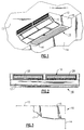
- evaporator unit 10 suitable for use in a small passenger bus of the type that has come into prominent use in recent years.
- small bus refers to a bus having a size and seating capacity that is less than a more conventional size bus, and which can seat between 10-30 passengers.
- This type of bus is sometimes referred to as a mini bus or a shuttle bus which is designed to transport a relatively small number of people over a relatively short distance.
- the air conditioning system presently used in conventional sized buses are generally unsuitable for use in smaller size mini buses because of size and shape.
- the air conditioning system employed in association with the present invention involves a condenser and a compressor that are mounted outside of the passenger compartment typically in the motor compartment of the vehicle.
- the system evaporator is contained in a low profile cabinet 12 that is mounted by suitable bracket in the ceiling 13 of the bus against the rear wall 14 of the passenger compartment. It should be evident that the cabinet can be mounted anywhere in the passenger compartment where it will not interfere with the comfort or mobility of the passengers.
- the cabinet extends substantially across the width of the passenger compartment and includes a main housing section 15 that is in fluid flow communication with a converging nose section 17.
- An air outlet 18 is located in the front wall of the nose section that contains one or more adjustable louver grates 20 that direct and distribute conditioned air leaving the evaporator unit along the ceiling of the passenger compartment. The leaving air stream is directed along the length of the passenger compartment, and over the driver's station before being circulated back to the rear of the passenger compartment.
- an evaporator coil 25 is mounted in the front part of the main housing section of the cabinet and extends substantially across the width of the cabinet.
- the evaporator coil is tilted toward the rear of the cabinet to form an acute angle with the floor of the cabinet thereby reducing the amount of vertical space required to house the coil without appreciably sacrificing the heat transfer surface area of the coil.
- a tangential blower is mounted directly behind the evaporator coil within the main housing of the cabinet.
- the blower includes a modular blower wheel 32 that is rotatably mounted upon suitable bearings within the blower housing 35.
- the blower wheel is driven by a single motor 36 that is mounted outside the blower housing upon one end wall 37 of the housing.
- the blower is driven by a single or variable speed motor having a pulse width modulator or other form of controller 38 (Fig. 5) that can be regulated to control the flow of comfort air discharged from the evaporator.
- the variable speed motor is the only control necessary for regulating the flow of comfort air within the passenger compartment.
- Input air to the evaporator unit is drawn into the cabinet through an inlet grill 40 mounted In the floor of the main housing section beneath the blower housing.
- An air filter 43 is mounted inside the cabinet over the inlet grill.
- the grill is removable, thus providing ready access to a filter whereby the filter can be easily periodically changed when necessary.
- the blower wheel 32 is surrounded by a shroud 45 as illustrated in Fig. 5 to establish a diverging flow passage 50 around the wheel.
- Incoming air enters the blower wheel through a throat 51 that extends across the lower portion of the wheel above the air inlet duct.
- the air leaves the bower wheel in a generally horizontal direction through the exit region 53. Due to the shape of the air passage, the velocity of the air decreases while the pressure is increased.
- a baffle plate 55 is positioned at the exit of the blower flow passage with the top edge of the plate forming the lower lip of the exit region.
- the top edge of the baffle plate is positioned above the axial center line 57 of the blower wheel and extends downwardly at an angle to terminate along the lower back edge of the evaporator coil to create a diverging entrance region 60 to the evaporator coil.
- the baffle plate is arranged so that the air flow passing through the entrance to the evaporator coil is evenly distributed over the coil entrance area to produce uniform heat transfer throughout the coil.
- the cooled air passing through the coil enters the converging nose section where its velocity is increased and is then discharged from the cabinet through the outlet ducts 20.
- the cooled comfort air leaves the cabinet at a relatively high velocity and is directed along the ceiling of the passenger compartment to create a generally circular flow of air that circulates laterally through the passenger compartment.
- a pan 63 is mounted upon the floor 64 of the main housing section of the cabinet directly beneath the evaporator coil 25 to collect condensate from the coil.
- the floor slopes downwardly toward the rear wall 14 of the passenger compartment so that condensate collected in the pan moves to the back of the pan under the influence of gravity.
- the back of the pan extends rearwardly beyond the lower back edge of the evaporator coil and is exposed to the blower wheel which causes a positive pressure to be exerted upon the condensate collected in the pan.
- Drain lines 68 are mounted in the back wall of the pan and pass rearwardly on either side of the cabinet air inlet duct 43. The drain lines pass through the rear wall of the cabinet and the rear wall of the passenger compartment and pass downwardly below the bus chassis to release the condensate to ambient.
- Figs. 6-10 there is illustrated in schematic form the modular blower arrangement used in the practice of the present invention.
- the present evaporator unit is designed so that different length wheels can be employed with a single variable speed motor.
- the axial length of the blower can be changed by simply interconnecting two different length wheels end to end.
- One wheel 71 has an axial length X while the second wheel 72 has a shorter length Y.
- the wheels can be brought together in various combinations to provide five modules of different lengths.
- blower units of different lengths can be constructed using a minimum amount of parts which, in turn, can be employed in different size cabinets.
- the wheels are cojoined together and joined to the single drive motor by connectors 76 and 77, respectively, or any other suitable connector that will provide for ease of interchangeability of the wheels.
- a single drive motor as described above is used in conjunction with each configuration with the speed of the motor being regulated to accommodate the demands of the specific configurations without considerably sacrificing efficiency and performance.
- the blower motor is shown positioned at one end of the wheel assembly, it can also be mounted between wheel sections to drive one or more sections from both sides of the motor.
- the present invention provides for an extremely low profile evaporator unit that can be mounted at the rear of the passenger compartment of a small bus where it will not interfere with the passengers' ability to move freely about the compartment.
- the unit through its drainage system, can efficiently remove condensate from the passenger compartment without the danger of leakage.
- the modular blower wheel design used in conjunction with a single pulse width modulated controlled motor allows for accurate control over the motor speed resulting in higher efficiency in performance with a lower current drain on the buses electrical system.
Landscapes
- Physics & Mathematics (AREA)
- Thermal Sciences (AREA)
- Engineering & Computer Science (AREA)
- Mechanical Engineering (AREA)
- Air-Conditioning For Vehicles (AREA)
- Structures Of Non-Positive Displacement Pumps (AREA)
Applications Claiming Priority (2)
| Application Number | Priority Date | Filing Date | Title |
|---|---|---|---|
| US393562 | 1999-09-10 | ||
| US09/393,562 US6105383A (en) | 1999-09-10 | 1999-09-10 | Evaporator unit for small bus |
Publications (3)
| Publication Number | Publication Date |
|---|---|
| EP1083068A2 true EP1083068A2 (de) | 2001-03-14 |
| EP1083068A3 EP1083068A3 (de) | 2003-10-08 |
| EP1083068B1 EP1083068B1 (de) | 2006-11-08 |
Family
ID=23555244
Family Applications (1)
| Application Number | Title | Priority Date | Filing Date |
|---|---|---|---|
| EP00203108A Expired - Lifetime EP1083068B1 (de) | 1999-09-10 | 2000-09-06 | Verdampfereinheit für Kleinbus |
Country Status (11)
| Country | Link |
|---|---|
| US (1) | US6105383A (de) |
| EP (1) | EP1083068B1 (de) |
| CN (1) | CN1106300C (de) |
| AR (1) | AR025613A1 (de) |
| AU (1) | AU738412B2 (de) |
| BR (1) | BR0004070A (de) |
| CA (1) | CA2315973C (de) |
| DE (1) | DE60031747T2 (de) |
| ES (1) | ES2270786T3 (de) |
| MX (1) | MXPA00008574A (de) |
| MY (1) | MY133709A (de) |
Cited By (2)
| Publication number | Priority date | Publication date | Assignee | Title |
|---|---|---|---|---|
| US6880354B2 (en) | 2003-05-05 | 2005-04-19 | Carrier Corporation | Condensate pump for rooftop air conditioning unit |
| KR100917174B1 (ko) | 2003-02-20 | 2009-09-15 | 한라공조주식회사 | 차량용 공기조화장치 |
Families Citing this family (31)
| Publication number | Priority date | Publication date | Assignee | Title |
|---|---|---|---|---|
| IT1311815B1 (it) * | 1999-01-28 | 2002-03-19 | Tecnosystemi Srl | Struttura di contenitore da incasso,particolarmente per lapredisposizione di impianti di condizionamento dell'aria. |
| US6742582B1 (en) * | 2000-01-20 | 2004-06-01 | Vent-Rite Valve Corp. | Modular climate control unit |
| US6318109B1 (en) * | 2000-08-30 | 2001-11-20 | Carrier Corporation | Low profile evaporator cabinet |
| CA2394689A1 (en) * | 2001-07-25 | 2003-01-25 | Nobuya Nakagawa | Air-conditioning system for a vehicle |
| US6523363B1 (en) * | 2001-10-24 | 2003-02-25 | Carrier Corporation | Evaporator with plastic outer covering |
| FR2852890B1 (fr) * | 2003-03-28 | 2006-06-23 | Valeo Climatisation | Dispositif de distribution d'air pour vehicule |
| CN100359257C (zh) * | 2003-05-20 | 2008-01-02 | 乐金电子(天津)电器有限公司 | 管道型空调凝结水排水结构 |
| FR2864806B1 (fr) * | 2004-01-07 | 2006-03-31 | Hispacold France | Dispositif de rafraichissement d'air compact, notamment pour climatisation de vehicule de transport en commun |
| WO2005085716A1 (en) * | 2004-03-04 | 2005-09-15 | Lg Electronics Inc. | Indoor unit in air conditioner |
| CN100434826C (zh) * | 2004-06-09 | 2008-11-19 | 乐金电子(天津)电器有限公司 | 窗式空调器的冷凝水引导结构 |
| US7543458B1 (en) | 2005-02-04 | 2009-06-09 | James Wurth | Portable vapor cycle air conditioning unit for small aircraft |
| WO2007012157A1 (en) * | 2005-07-29 | 2007-02-01 | Carrier Corporation | Condensate drain hose arrangement for an evaporator unit |
| US7730742B2 (en) * | 2006-12-22 | 2010-06-08 | Whirlpool Corporation | Accelerated heat exchanger |
| BRPI0721861A2 (pt) * | 2007-07-24 | 2014-02-18 | Carrier Corp | Sistemas de refrigeração de reboque |
| US8037704B2 (en) * | 2008-05-22 | 2011-10-18 | Thermo King Corporation | Distributed refrigeration system |
| JP2011020520A (ja) * | 2009-07-14 | 2011-02-03 | Keihin Corp | ドレンパン |
| US20110252817A1 (en) * | 2010-04-20 | 2011-10-20 | Sub-Zero, Inc. | Air flow system for appliances |
| JP5610839B2 (ja) * | 2010-05-11 | 2014-10-22 | 株式会社日立製作所 | 冷却システム |
| JP5849500B2 (ja) * | 2011-07-30 | 2016-01-27 | スズキ株式会社 | リアクーリングユニットの仮保持構造 |
| US8650895B2 (en) | 2012-01-25 | 2014-02-18 | Thermo King Corporation | Method for constructing air conditioning systems with universal base units |
| FR3001532B1 (fr) * | 2013-01-25 | 2019-08-02 | Hengel Industrie | Dispositif ameliore de surgelation et de conservation |
| US11465463B2 (en) * | 2015-02-23 | 2022-10-11 | Carrier Corporation | Transport refrigeration unit |
| SG11201706658QA (en) * | 2015-02-27 | 2017-09-28 | Daikin Ind Ltd | Refrigeration apparatus for containers |
| US10865798B2 (en) * | 2016-05-30 | 2020-12-15 | Zhongshan Broad-Ocean Motor Co., Ltd. | Fan coil unit |
| WO2018078850A1 (ja) | 2016-10-31 | 2018-05-03 | 三菱電機株式会社 | 室内機および空気調和装置 |
| CN107120873A (zh) * | 2017-06-30 | 2017-09-01 | 广东美芝制冷设备有限公司 | 蒸发器组件、车载空调系统及车辆 |
| ES2925959T3 (es) * | 2018-12-11 | 2022-10-20 | Denso Thermal Systems Spa | Sistema de aire acondicionado provisto de un separador de gotas, en particular, para un vehículo a motor |
| US10871306B2 (en) | 2019-01-02 | 2020-12-22 | Johnson Controls Technology Company | Modular drain pans for HVAC systems |
| US11661199B2 (en) | 2019-10-21 | 2023-05-30 | Peter Schiff | Removable auxiliary air conditioning system for a confined area |
| FR3105370A1 (fr) * | 2019-12-20 | 2021-06-25 | Valeo Systemes Thermiques | Module de ventilation pour véhicule automobile à turbomachine tangentielle |
| CN115540438A (zh) * | 2022-09-05 | 2022-12-30 | 浙江双友物流器械股份有限公司 | 一种移动式冷藏箱 |
Family Cites Families (6)
| Publication number | Priority date | Publication date | Assignee | Title |
|---|---|---|---|---|
| US4098093A (en) * | 1976-12-06 | 1978-07-04 | Vapor Corporation | Unitary cab air cooling system for large off road vehicles |
| US4549405A (en) * | 1983-12-12 | 1985-10-29 | Carrier Corporation | Modular air conditioning unit for mobile cargo container |
| DE3519044A1 (de) * | 1984-05-28 | 1985-11-28 | Mitsubishi Denki K.K., Tokio/Tokyo | Kuehler fuer kraftfahrttechnische verwendung und kraftfahrzeug-klimaanlage |
| US4888959A (en) * | 1989-02-09 | 1989-12-26 | Thermo King Corporation | Bus air conditioner suitable for mounting within the normal profile of a bus |
| US5619862A (en) * | 1995-08-11 | 1997-04-15 | Bergstrom Manufacturing Co. | Multi-channel motor vehicle ventilation apparatus |
| US5894737A (en) * | 1997-03-20 | 1999-04-20 | Pro Air, Inc. | Housing with integral drain for removing condensate from a heating and air conditioning unit |
-
1999
- 1999-09-10 US US09/393,562 patent/US6105383A/en not_active Expired - Fee Related
-
2000
- 2000-08-15 CA CA002315973A patent/CA2315973C/en not_active Expired - Fee Related
- 2000-08-23 MY MYPI20003888 patent/MY133709A/en unknown
- 2000-09-01 MX MXPA00008574A patent/MXPA00008574A/es active IP Right Grant
- 2000-09-05 CN CN00126989A patent/CN1106300C/zh not_active Expired - Fee Related
- 2000-09-06 EP EP00203108A patent/EP1083068B1/de not_active Expired - Lifetime
- 2000-09-06 DE DE60031747T patent/DE60031747T2/de not_active Expired - Lifetime
- 2000-09-06 ES ES00203108T patent/ES2270786T3/es not_active Expired - Lifetime
- 2000-09-08 BR BR0004070-3A patent/BR0004070A/pt not_active IP Right Cessation
- 2000-09-08 AU AU56599/00A patent/AU738412B2/en not_active Ceased
- 2000-09-08 AR ARP000104727A patent/AR025613A1/es active IP Right Grant
Non-Patent Citations (1)
| Title |
|---|
| None |
Cited By (4)
| Publication number | Priority date | Publication date | Assignee | Title |
|---|---|---|---|---|
| KR100917174B1 (ko) | 2003-02-20 | 2009-09-15 | 한라공조주식회사 | 차량용 공기조화장치 |
| US6880354B2 (en) | 2003-05-05 | 2005-04-19 | Carrier Corporation | Condensate pump for rooftop air conditioning unit |
| WO2004098922A3 (en) * | 2003-05-05 | 2006-01-19 | Carrier Corp | Condensate pump for rooftop air conditioning unit |
| CN100415552C (zh) * | 2003-05-05 | 2008-09-03 | 开利公司 | 用于车顶空调单元的冷凝水泵 |
Also Published As
| Publication number | Publication date |
|---|---|
| DE60031747T2 (de) | 2007-08-23 |
| AU5659900A (en) | 2001-03-15 |
| DE60031747D1 (de) | 2006-12-21 |
| CA2315973A1 (en) | 2001-03-10 |
| EP1083068A3 (de) | 2003-10-08 |
| AU738412B2 (en) | 2001-09-20 |
| AR025613A1 (es) | 2002-12-04 |
| US6105383A (en) | 2000-08-22 |
| CA2315973C (en) | 2003-12-30 |
| CN1287927A (zh) | 2001-03-21 |
| ES2270786T3 (es) | 2007-04-16 |
| EP1083068B1 (de) | 2006-11-08 |
| BR0004070A (pt) | 2001-04-03 |
| MY133709A (en) | 2007-11-30 |
| MXPA00008574A (es) | 2003-07-28 |
| CN1106300C (zh) | 2003-04-23 |
Similar Documents
| Publication | Publication Date | Title |
|---|---|---|
| US6105383A (en) | Evaporator unit for small bus | |
| CA2413667C (en) | Ceiling assembly for the ducted type of rvac | |
| US6161609A (en) | Flow control apparatus | |
| US6134909A (en) | Evaporator housing | |
| US20060211364A1 (en) | Cooling system for motor vehicles and method for controlling at least one air mass flow through a radiator | |
| US5220808A (en) | Air conditioning unit for motor vehicle, particularly omnibuses | |
| EP2046592B1 (de) | Vorrichtung zur elektrostatischen zerstäubung zur verwendung in einem fahrzeug | |
| US20110061414A1 (en) | Rooftop mounted air conditioner | |
| DE4002909C2 (de) | Klimaanlage für Omnibusse | |
| CA1279479C (en) | Bus air conditioning unit | |
| EP1620285B1 (de) | Vorrichtung zum entfernen von kondensat von einer dach-klimaanlage | |
| US4549405A (en) | Modular air conditioning unit for mobile cargo container | |
| EP3109075A1 (de) | Bedienerstation | |
| EP1310392B1 (de) | Klimaanlage für einen Transportcontainer | |
| US6595499B2 (en) | Evaporating unit for an air acclimatizer | |
| CN100478207C (zh) | 空调机组 | |
| US5588305A (en) | Air conditioning system for a vehicle | |
| HK1034056A (en) | Evaporator unit for small bus | |
| KR102714461B1 (ko) | 차량용 공조장치 | |
| HU180201B (en) | Device for heating and ventilating vehicles | |
| JPS584622A (ja) | 車両冷房装置 | |
| CN121403943B (zh) | 用于车辆的hvac总成及车辆 | |
| US20250303819A1 (en) | Outside Air Introduction Device and HVAC System for Vehicle Including the Same | |
| CN109109622B (zh) | 一种汽车 | |
| KR0121968B1 (ko) | 버스용 냉방덕트장치 |
Legal Events
| Date | Code | Title | Description |
|---|---|---|---|
| PUAI | Public reference made under article 153(3) epc to a published international application that has entered the european phase |
Free format text: ORIGINAL CODE: 0009012 |
|
| AK | Designated contracting states |
Kind code of ref document: A2 Designated state(s): AT BE CH CY DE DK ES FI FR GB GR IE IT LI LU MC NL PT SE |
|
| AX | Request for extension of the european patent |
Free format text: AL;LT;LV;MK;RO;SI |
|
| PUAL | Search report despatched |
Free format text: ORIGINAL CODE: 0009013 |
|
| AK | Designated contracting states |
Kind code of ref document: A3 Designated state(s): AT BE CH CY DE DK ES FI FR GB GR IE IT LI LU MC NL PT SE |
|
| AX | Request for extension of the european patent |
Extension state: AL LT LV MK RO SI |
|
| 17P | Request for examination filed |
Effective date: 20031006 |
|
| AKX | Designation fees paid |
Designated state(s): DE ES FR IT |
|
| GRAP | Despatch of communication of intention to grant a patent |
Free format text: ORIGINAL CODE: EPIDOSNIGR1 |
|
| GRAS | Grant fee paid |
Free format text: ORIGINAL CODE: EPIDOSNIGR3 |
|
| GRAA | (expected) grant |
Free format text: ORIGINAL CODE: 0009210 |
|
| AK | Designated contracting states |
Kind code of ref document: B1 Designated state(s): DE ES FR IT |
|
| PG25 | Lapsed in a contracting state [announced via postgrant information from national office to epo] |
Ref country code: IT Free format text: LAPSE BECAUSE OF FAILURE TO SUBMIT A TRANSLATION OF THE DESCRIPTION OR TO PAY THE FEE WITHIN THE PRESCRIBED TIME-LIMIT;WARNING: LAPSES OF ITALIAN PATENTS WITH EFFECTIVE DATE BEFORE 2007 MAY HAVE OCCURRED AT ANY TIME BEFORE 2007. THE CORRECT EFFECTIVE DATE MAY BE DIFFERENT FROM THE ONE RECORDED. Effective date: 20061108 |
|
| REF | Corresponds to: |
Ref document number: 60031747 Country of ref document: DE Date of ref document: 20061221 Kind code of ref document: P |
|
| RAP2 | Party data changed (patent owner data changed or rights of a patent transferred) |
Owner name: CARRIER CORPORATION |
|
| REG | Reference to a national code |
Ref country code: ES Ref legal event code: FG2A Ref document number: 2270786 Country of ref document: ES Kind code of ref document: T3 |
|
| ET | Fr: translation filed | ||
| PLBE | No opposition filed within time limit |
Free format text: ORIGINAL CODE: 0009261 |
|
| STAA | Information on the status of an ep patent application or granted ep patent |
Free format text: STATUS: NO OPPOSITION FILED WITHIN TIME LIMIT |
|
| 26N | No opposition filed |
Effective date: 20070809 |
|
| PGFP | Annual fee paid to national office [announced via postgrant information from national office to epo] |
Ref country code: ES Payment date: 20090907 Year of fee payment: 10 |
|
| PGFP | Annual fee paid to national office [announced via postgrant information from national office to epo] |
Ref country code: DE Payment date: 20090930 Year of fee payment: 10 |
|
| PGFP | Annual fee paid to national office [announced via postgrant information from national office to epo] |
Ref country code: IT Payment date: 20090912 Year of fee payment: 10 |
|
| PG25 | Lapsed in a contracting state [announced via postgrant information from national office to epo] |
Ref country code: IT Free format text: LAPSE BECAUSE OF NON-PAYMENT OF DUE FEES Effective date: 20100906 |
|
| REG | Reference to a national code |
Ref country code: FR Ref legal event code: ST Effective date: 20110531 |
|
| REG | Reference to a national code |
Ref country code: DE Ref legal event code: R119 Ref document number: 60031747 Country of ref document: DE Effective date: 20110401 |
|
| PG25 | Lapsed in a contracting state [announced via postgrant information from national office to epo] |
Ref country code: DE Free format text: LAPSE BECAUSE OF NON-PAYMENT OF DUE FEES Effective date: 20110401 Ref country code: FR Free format text: LAPSE BECAUSE OF NON-PAYMENT OF DUE FEES Effective date: 20100930 |
|
| PGFP | Annual fee paid to national office [announced via postgrant information from national office to epo] |
Ref country code: FR Payment date: 20090916 Year of fee payment: 10 |
|
| REG | Reference to a national code |
Ref country code: ES Ref legal event code: FD2A Effective date: 20111019 |
|
| PG25 | Lapsed in a contracting state [announced via postgrant information from national office to epo] |
Ref country code: ES Free format text: LAPSE BECAUSE OF NON-PAYMENT OF DUE FEES Effective date: 20100907 |