EP1083079A2 - Dispositif afficheur - Google Patents
Dispositif afficheur Download PDFInfo
- Publication number
- EP1083079A2 EP1083079A2 EP00119654A EP00119654A EP1083079A2 EP 1083079 A2 EP1083079 A2 EP 1083079A2 EP 00119654 A EP00119654 A EP 00119654A EP 00119654 A EP00119654 A EP 00119654A EP 1083079 A2 EP1083079 A2 EP 1083079A2
- Authority
- EP
- European Patent Office
- Prior art keywords
- display unit
- display
- enclosure
- display panel
- opening portion
- Prior art date
- Legal status (The legal status is an assumption and is not a legal conclusion. Google has not performed a legal analysis and makes no representation as to the accuracy of the status listed.)
- Granted
Links
Images




Classifications
-
- B—PERFORMING OPERATIONS; TRANSPORTING
- B60—VEHICLES IN GENERAL
- B60K—ARRANGEMENT OR MOUNTING OF PROPULSION UNITS OR OF TRANSMISSIONS IN VEHICLES; ARRANGEMENT OR MOUNTING OF PLURAL DIVERSE PRIME-MOVERS IN VEHICLES; AUXILIARY DRIVES FOR VEHICLES; INSTRUMENTATION OR DASHBOARDS FOR VEHICLES; ARRANGEMENTS IN CONNECTION WITH COOLING, AIR INTAKE, GAS EXHAUST OR FUEL SUPPLY OF PROPULSION UNITS IN VEHICLES
- B60K35/00—Instruments specially adapted for vehicles; Arrangement of instruments in or on vehicles
- B60K35/20—Output arrangements, i.e. from vehicle to user, associated with vehicle functions or specially adapted therefor
- B60K35/21—Output arrangements, i.e. from vehicle to user, associated with vehicle functions or specially adapted therefor using visual output, e.g. blinking lights or matrix displays
- B60K35/22—Display screens
-
- B—PERFORMING OPERATIONS; TRANSPORTING
- B60—VEHICLES IN GENERAL
- B60K—ARRANGEMENT OR MOUNTING OF PROPULSION UNITS OR OF TRANSMISSIONS IN VEHICLES; ARRANGEMENT OR MOUNTING OF PLURAL DIVERSE PRIME-MOVERS IN VEHICLES; AUXILIARY DRIVES FOR VEHICLES; INSTRUMENTATION OR DASHBOARDS FOR VEHICLES; ARRANGEMENTS IN CONNECTION WITH COOLING, AIR INTAKE, GAS EXHAUST OR FUEL SUPPLY OF PROPULSION UNITS IN VEHICLES
- B60K35/00—Instruments specially adapted for vehicles; Arrangement of instruments in or on vehicles
- B60K35/20—Output arrangements, i.e. from vehicle to user, associated with vehicle functions or specially adapted therefor
- B60K35/29—Instruments characterised by the way in which information is handled, e.g. showing information on plural displays or prioritising information according to driving conditions
-
- B—PERFORMING OPERATIONS; TRANSPORTING
- B60—VEHICLES IN GENERAL
- B60K—ARRANGEMENT OR MOUNTING OF PROPULSION UNITS OR OF TRANSMISSIONS IN VEHICLES; ARRANGEMENT OR MOUNTING OF PLURAL DIVERSE PRIME-MOVERS IN VEHICLES; AUXILIARY DRIVES FOR VEHICLES; INSTRUMENTATION OR DASHBOARDS FOR VEHICLES; ARRANGEMENTS IN CONNECTION WITH COOLING, AIR INTAKE, GAS EXHAUST OR FUEL SUPPLY OF PROPULSION UNITS IN VEHICLES
- B60K35/00—Instruments specially adapted for vehicles; Arrangement of instruments in or on vehicles
- B60K35/50—Instruments characterised by their means of attachment to or integration in the vehicle
-
- B—PERFORMING OPERATIONS; TRANSPORTING
- B60—VEHICLES IN GENERAL
- B60K—ARRANGEMENT OR MOUNTING OF PROPULSION UNITS OR OF TRANSMISSIONS IN VEHICLES; ARRANGEMENT OR MOUNTING OF PLURAL DIVERSE PRIME-MOVERS IN VEHICLES; AUXILIARY DRIVES FOR VEHICLES; INSTRUMENTATION OR DASHBOARDS FOR VEHICLES; ARRANGEMENTS IN CONNECTION WITH COOLING, AIR INTAKE, GAS EXHAUST OR FUEL SUPPLY OF PROPULSION UNITS IN VEHICLES
- B60K35/00—Instruments specially adapted for vehicles; Arrangement of instruments in or on vehicles
- B60K35/50—Instruments characterised by their means of attachment to or integration in the vehicle
- B60K35/53—Movable instruments, e.g. slidable
-
- B—PERFORMING OPERATIONS; TRANSPORTING
- B60—VEHICLES IN GENERAL
- B60K—ARRANGEMENT OR MOUNTING OF PROPULSION UNITS OR OF TRANSMISSIONS IN VEHICLES; ARRANGEMENT OR MOUNTING OF PLURAL DIVERSE PRIME-MOVERS IN VEHICLES; AUXILIARY DRIVES FOR VEHICLES; INSTRUMENTATION OR DASHBOARDS FOR VEHICLES; ARRANGEMENTS IN CONNECTION WITH COOLING, AIR INTAKE, GAS EXHAUST OR FUEL SUPPLY OF PROPULSION UNITS IN VEHICLES
- B60K37/00—Dashboards
Definitions
- the present invention relates to a display device mounted in a moving body such as a motor vehicle, and having a display portion detachable from a box.
- a motor vehicle incorporates a display unit equipped with a liquid crystal display panel, such as a television receiver and a car navigation system.
- the display unit for the car navigation system makes several kinds of indications inclusive of the present location of a vehicle.
- the display unit has been demanded to display the information indicated by the car navigation system more clearly and wide variety of items of information of an electric appliance mounted in the vehicle, e.g. operation status and setting status of a car audio (tuner, CD deck, etc) and an air conditioner.
- the display unit has a tendency being up-sized. However, this up-sizing has made it difficult to assure the space for installing the display unit.
- the display system disclosed in these publications includes an enclosure or box and a display unit for information display which can be freely loaded/unloaded into/from the enclosure from an opening portion.
- the enclosure is attached to an instrument panel or console box in a state where the opening is opposite to a vehicle driver.
- the display unit is provided so that it can be freely loaded/unloaded into/from the instrument panel or console box.
- the display unit While the display device is being used, the display unit is unloaded from the enclosure. While it is no being used, The display unit remains loaded in the body. More specifically, while the display device is not used, the end face of the display unit is opposite to the vehicle driver through the opening portion.
- An object of the present invention is to provide a display device which can display a wide variety of information such as information for various electric appliances and suppress or effectively use an installing space.
- a display device comprising: an enclosure; a first display unit provided so that it can be freely loaded from/into the enclosure; a second display unit provided in front of the first display unit in a direction of unloading the first display unit from the enclosure.
- the display device since the display device is equipped with the first display unit for displaying various items of information of a car navigation system and the second display unit for displaying other kinds of information such as the setting status of an air conditioner. Therefore, the display device can display a wide variety of information such as the information from various kinds of electric appliances.
- the first display unit is provided so that it can be freely loaded/unloaded in/from the enclosure
- the second display unit is arranged in front of the first display unit.
- the space for installing the first and the second display units can be limited. Accordingly, the space for installing the display device 1 itself can be limited and can be used effectively.
- the enclosure has an opening portion through which the first display unit is loaded/unloaded
- the second display unit includes a display panel for displaying information and a frame member for enclosing the second display panel so that whereby when the first display unit is loaded/unloaded in/from the enclosure, an end face of the frame member is opposite to the opening portion of the enclosure.
- the space for installing the second display unit can be suppressed.
- the space for installing the display device itself can be suppressed and can be used effectively.
- a display device 1 serves to display information for various electric appliances such as a car navigation system and an air conditioner mounted in an instrument panel D of the vehicle which is a moving body.
- the display device 1 includes a box or enclosure 1, a first display unit 3 (a first display portion) which is freely loaded/unloaded into/from the enclosure, a second display unit 6 (a second display portion), first driving mechanism 9 (Fig. 5 and others), etc.
- the enclosure 1 as seen from Figs. 1 to 4, is box-shaped which is mounted in an instrument panel D or the like.
- the enclosure 2 includes an opening portion 2a opposite to the section of a vehicle occupant when it is mounted in the instrument panel and an operation switch (not shown).
- the first display unit 3 is loaded/unloaded into/from the enclosure 1 through the opening portion 2a.
- a room 2b where an electric appliance is accommodated is formed below the opening portion 2a.
- the room 2b accommodates an electric appliance 10 such as a tuner of a car audio or a CD deck.
- the CD deck is accommodated.
- the room 2b has an open wall opposite to the driver so that the electric appliance 10 can be operated.
- a pivotal shaft 7 is provided in the vicinity of the lower edge of the opening portion 2a of the enclosure 1.
- the pivotal shaft 7 is extended widthwise of the opening portion 2a and the enclosure 2.
- the pivotal shaft 7 is located at a position protruding from the peripheral edge of the enclosure 2 toward the driver.
- the pivotal shaft 7 is supported by a bottom member 8 attached to the enclosure 2.
- the first display unit 3 includes a display panel 3a (e.g. liquid crystal display panel) for displaying the information such as a character and an image for a driver, and an enclosure or frame member 3b for accommodating the first display panel.
- the display panel 3a serves to display the various items of information of the car navigation system and serves as a display portion of a television receiver.
- the frame member 3b has a size enough to be accommodated in the enclosure 2.
- the first display unit 3 is loaded in the enclosure 2 so that the display panel 3a is oriented downward.
- the first display unit 3 is supported by the first driving mechanism 9 so that it can be freely loaded/unloaded into/from the enclosure 2.
- the second display unit 6 includes a display panel 6a (e.g. liquid crystal panel) for displaying the information such as a character and an image for a driver, and an enclosure or frame member 6b for accommodating the display panel 6a.
- the display panel 6a serves to display the various items of information such as the setting status of a CD deck which is an electric appliance and various items of information such as the setting information and the operating information of an air conditioner.
- the frame member 6b is shaped like a square box when viewed from the front.
- the second display unit 6 is arranged so that the display panel 6a is opposite to the driver 6a and lengthy horizontally when viewed from the driver.
- the second display unit 6 is formed so that its display panel 6a has a smaller size than the display panel 3a.
- the second display unit 6 is pivotally supported at its lower edge 6c by the pivotal shaft 7.
- the second display unit 6 is pivotally supported by the pivotal shaft 7 so that the opening portion 2a can be freely opened/closed.
- the second display unit 6 is urged by an urging means such as a spring (not shown) in a direction of closing the opening portion 2a around the pivotal shaft 7.
- the second display unit 6 is pivotally supported by the pivotal shaft 7 so that it is located in front of the first display unit 3 when the first display unit 3 is located at both positions of a loading position and a viewing position (described later) in a direction of unloading the display unit 3 from the enclosure 2.
- the second display unit 6 is located in its end face 6d, which is located on the side opposite to the display panel 6a, oppositely to the opening portion 2a by the urging force of the urging means such as the spring when the first display unit 3 is located at the viewing position described later or loading position.
- the secondary display unit 6 is held with the end face 6d in contact with the peripheral edge of the enclosure 2 constituting the opening portion 2a.
- the first driving mechanism 9 includes a sub-chassis 11, a shifting mechanism 4 and a first rotary supporting mechanism 5.
- the sub-chassis 11, as shown in Figs. 5 and 7, is attached to the outside of the frame member 3b of the first display unit 3.
- the sub-chassis 11, as seen from Figs. 6 and 8, includes a chassis bottom wall 11a opposite to the bottom wall of the enclosure member 3a and chassis side walls 11b opposite to the side walls successive to the bottom wall of the frame member 3a.
- the sub-chassis 11 is arranged to cover the frame member 3a from its outer periphery. When the first display unit 3 is loaded within the enclosure 2, the sub-chassis 11 extends from the end 3c at the inside of the first display unit 3 to the inner wall 2b of the enclosure 2 which is farthest from the driver 2b.
- the sub-chassis 11 is supported shiftably by the shifting mechanism 4 in the depth direction of the enclosure 2 between state where the display unit 3 is loaded in the enclosure 2 and the state where it is unloaded from the enclosure 2 through the opening portion 2a.
- the sub-chassis 11 is equipped with a pivotal shaft 14 at the end 11c (Figs. 5 and 7) located on the side of the driver.
- the pivotal shaft 14 extends widthwise of the enclosure 2 or display device 1.
- the pivotal shaft 14 supports the one end 3c of the first display unit 3. Incidentally, in the state (Fig. 4) where the display panel 3a is opposite to the driver, the one end 3c is located at the bottom of the frame member 3b. In the state (Fig. 3) where the display panel 3a is oriented downward, the one end 3c is located at the inner side of the frame member 3b.
- the pivotal shaft 14 is rotatably provided around the axis of the sub-chassis 11 and also secured to the first display unit 3. Namely, the pivotal shaft 14 is rotated together with the first display unit 3 and independently of the sub-chassis 11.
- the shifting mechanism 4 serves to move the sub-chassis 11 in the depth direction of the enclosure 2.
- the shifting mechanism 4 moves the sub-chassis 11 so that the first display unit 3 is loaded/unloaded in/from the enclosure 2.
- the shifting mechanism 4 as seen from Figs. 5 and 7, includes a driving motor 21 and a sliding mechanism 22.
- the driving motor 21 is attached to the sub-chassis 11, and is equipped with a worm gear 23 at its output shaft.
- the sliding mechanism 22 includes a plurality of gears 24 in mesh with one another, a shifting gear 15 in mesh with one of these gears 24, a slave gear 26 in parallel to the shifting gear 25, a coupling shaft 27 for coupling the shifting gear 25 and slave gear 26 with each other and a pair of racks 28.
- Another of the gears 24 is in mesh with the worm gear 23.
- the shifting gear 25 and the slave gear 26 are arranged apart from each other widthwise of the display device 1.
- the coupling shaft 27 is rotatably supported by the sub-chassis 11.
- the pair of racks 28 are arranged apart from each other widthwise of the display device 1.
- the racks 28 are secured to the enclosure 2, respectively.
- These racks 28 are arranged in the depth direction of the enclosure 2.
- the one of the racks 28 is in mesh with the shifting gear 25, whereas the other thereof is in mesh with the slave gear 26.
- the shifting mechanism 4 makes e.g. a normal rotation of the driving motor 21 so that the sub-chassis 11 is shifted together with the first display unit 3 in a depth direction of the enclosure 2 outside the enclosure 2 from the state it has been loaded in the enclosure 2.
- the shifting mechanism 4 makes e.g. a reverse rotation of the driving motor 21 so that the sub-chassis 11 is shifted together with the display unit 3 into the enclosure 2 from the state where it has been unloaded from the enclosure 2.
- the first rotary supporting mechanism 5 includes a first driving motor for rotation (rotary driving motor) 31 and a first rotary mechanism 32.
- the first rotary driving motor 31 is attached to the sub-chassis 11, and is equipped with a worm gear 33 at its output shaft.
- the first rotary mechanism 32 includes a plurality of gears 34 which are in mesh with one another and driving gears 35 coaxially attached to the above pivotal shaft 14.
- the driving gears 35 rotate together with the pivotal shaft 14.
- One of the plurality of gears 34 is in mesh with the worm gear 33 and another thereof is in mesh with one of the driving gears 35.
- the first rotary supporting mechanism 5 makes e.g. a normal rotation of the first rotary driving motor 31 so that the display unit 3 unloaded from the enclosure 2 by the shifting mechanism 4 is rotated around the one end 3c of the display unit 3 so that the display panel 3a is rotated from the state it is oriented downward to the state where it is opposite to the front of an occupant section or the driver.
- the first rotary supporting mechanism 5 makes e.g. a reverse rotation of the first rotary driving motor 31 so that the display panel 3a is rotated around the one end 3c of the display unit 3 from the state where it is opposite to the driver to the state where the it is oriented downward.
- the first driving mechanism 9 supports the first display unit 3 so as to be movable between the loading position where it is loaded in the enclosure 2 and a viewing position where the information on the display panel 3a is presented for the visual recognition of the driver.
- the end face 6d of the second display unit 6 is opposite to the opening portion 2a.
- the display panel 6a is opposite to the driver and the end face 6d is in contact with the peripheral edge of the enclosure 2 constituting the opening portion 20.
- the driving motor 21 When the operation switch is operated, the driving motor 21 is rotated in a normal direction so that the first display unit 3 as well as the sub-chassis 11 is unloaded or discharged from the enclosure 2. As the first display unit 3 is unloaded from the enclosure 2, the first display unit 3 pushes the second display unit 6 against the urging force of the urging means such as a spring. Then, the second display unit 6 is rotated around the pivotal shaft 7 in a direction of opening the opening portion 2a.
- the first rotary driving motor 31 is rotated in the normal direction so that the first display unit 3 is rotated for the sub-chassis 11 around the pivotal shaft 14.
- the display panel 3a is located at the viewing position where the information on the display panel 3a is presented for the visual recognition of the driver.
- the second display unit 6 is gradually rotated around the pivotal shaft 7 in a direction so as to make the display panel 6a opposite to the driver.
- the first and second display units 3 and 6 are located at the positions where the driver can visually recognize the information displayed on the display panels 3a and 6a.
- the operation switch When the operation switch is operated in the state of the display units 3 and 6 shown in Fig. 4, the first rotary driving motor 31 starts to rotate in a reverse direction, for example.
- the first display unit 3 gradually rotates around the pivotal shaft 14 in a direction so as to orient the display panel 3a downward.
- the second display unit 6 is pushed by the first display unit 3 so that it gradually rotates in a direction so as to orient the display panel 6a downward.
- the first rotary driving motor 31 stops when the display units 3 and 6 have been rotated until the display panels 3a and 6a are completely oriented downward. At this time, the second display unit 6 is in a state of having opened the opening portion 2a. Then, the first rotary driving motor 31 starts to rotate in a reverse direction, for example. Correspondingly, the first display unit 3 is shifted into the enclosure 2 and eventually loaded therein.
- the second display 6 gradually rotates around the pivotal shaft 7 in a direction so as to make the display panel 6a opposite to the driver.
- the second display unit 6 When the first display unit 3 has been completely loaded in the enclosure 2, as shown in Fig. 2, the second display unit 6 is located so that the display panel 6a is opposite to the driver. At this time, the end face 6d of the second display unit 6 is opposite to the opening portion 2a.
- the display device provides the following advantages. Since it is equipped with the first display unit 3 for displaying various items of information of the car navigation system and the second display unit 6 for displaying other kinds of information such as the setting status of an air conditioner, it can display a wide variety of information such as the information from various kinds of electric appliances.
- the first display unit 3 is provided so that it can be freely loaded/unloaded in/from the enclosure 2, and the second display unit 6 is arranged in front of the first display unit 3.
- the space for installing the first and the second display units 3 and 6 can be limited. Accordingly, the space for installing the display device 1 itself can be limited and can be used effectively.
- the end face 6d of the frame 6b of the second display unit 6 is opposite to the opening portion 2a. Therefore, the space for installing the second display unit 6 can be limited. Accordingly, the space for installing the display device 1 itself can be limited and can be used effectively.
- the second display unit 6 is located so that the display panel 6a is opposite to the driver. Therefore, when the first display unit 3 is not used, several items of information of an electric appliance such as an air conditioner can be displayed on the display panel 6a of the second display unit 6.
- the second display unit 6 is pivotally supported on the pivotal shaft 7 arranged widthwise of the enclosure 2 so that it is urged in a direction of closing the opening portion 2a. For this reason, the space for installing the second display unit 6 can be limited effectively.
- the first display unit 3 As the first display unit 3 is shifted from the loading position to the viewing position and vice versa by the first driving mechanism 9, it pushes the second display unit 6 to rotate so that the opening portion 2a is opened. Thus, the first display unit 3 can be surely loaded/unloaded in/from the enclosure 2.
- the display panel 6a of the first display unit 6 is formed in a smaller size than that of the display panel 3a of the first display unit 3, the space for installing these display units can be limited and hence the space for installing the display device itself can be limited.
- the display device 1 can be provided which can display a wider variety of items of information and limit the space therefor.
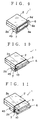
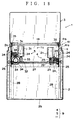
- the first display unit 3, as shown in Figs. 12 and 18, is supported on the sub-chassis 11 by a plurality of hinge means 41.
- the hinge means 41 are arranged apart from each other widthwise of the display device 1.
- Each hinge means 41 includes a first hinge piece 41a attached to the sub-chassis 11 and a second hinge piece 41b attached to the first display unit 3. These hinge pieces 41a and 41b are formed in a belt-shape.
- the one end of the first hinge piece 41a is attached to the end 11c of the sub-chassis 11, and the one end of the second hinge piece 41b of the one end 3c of the first display unit 3.
- These hinge pieces 41a and 41b are coupled with each other so that their other ends are rotatable.
- the second hinge piece 41b is coupled with the pivotal shaft 14 and driving gear 35 and is rotated together with them. In the configuration, when the first rotary driving motor 31 is driven, the first display unit 3 is rotated around the pivotal shaft 14 together with the second hinge piece 41b.
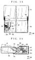
- a second driving mechanism 45 is attached to the bottom face of the enclosure 2.
- the second driving mechanism 45 as seen from Figs. 19 and 20, is provided with a chassis member 46 and a second rotary supporting mechanism 47.
- the chassis member 46 is attached to the lower portion of the opening portion 2a of the enclosure 2.
- the second rotary supporting mechanism 47 includes a second driving motor for rotation (rotary driving motor) 51 and a second rotary mechanism 52.
- the second rotary driving motor 51 is attached to the chassis member 46.
- the second rotary driving motor 51 is equipped with a worm gear 53 at its output shaft.
- the rotary mechanism 52 includes a plurality of gears 54 which are in mesh with one another and a driving gear 55 coaxially attached to the above pivotal shaft 7.
- the driving gear 55 rotates together with the pivotal shaft 7.
- One of the plurality of gears 54 is in mesh with the worm gear 53 and another thereof is in mesh with the driving gear 55.
- the second rotary driving mechanism 47 makes e.g. a normal rotation of the second rotary driving motor 51
- the second display unit 6 is rotated around the end 6c so that the display panel 3a is shifted from the state where it is oriented downward to the state where it is opposite to the front of an occupant section or the driver.
- the second rotary supporting mechanism 47 makes e.g. a reverse rotation of the second rotary driving motor 51 so that the display panel 6a is rotated around the one end 6c from the state where it is opposite to the driver to the state where the it is oriented downward.
- the end face 6d of the second display unit 6 is opposite to the opening portion 2a.
- the display panel 6a is opposite to the driver and the end face 6d is in contact with the peripheral edge of the enclosure 2 constituting the opening portion so that the opening portion 2a is closed.
- the driving motor for shifting 21 is rotated in a normal direction and the second rotary driving motor 51 is rotated in a reverse direction. Then, as seen from Figs. 10 and 11, the first display unit 3 as well as the sub-chassis 11 is unloaded or discharged from the enclosure 2. Simultaneously, the second display unit 6 is rotated around the pivotal shaft 7 in a direction of opening the opening portion 2a until it is oriented downward.
- the driving motor 21 stops. Incidentally, the driving motor 21, which is being driven in a normal direction, continues to unload the first display unit 3 from the enclosure 2.
- the driving motor 21 stops. At this time, the display panel 3a of the first display unit 3 is oriented downward.
- the first rotary driving motor 31 is rotated in the normal direction so that the first display unit 3 is rotated around the pivotal shaft 14 as shown in Figs. 13 and 14.
- the display panel 3a is located at the viewing position where it is opposite to the front of an occupant or driver and the information on the display panel 3a is presented for the visual recognition of the driver.
- the first rotary driving motor 31 stops. Then, the second driving motor 51 of the second rotary supporting mechanism 47 is driven in the normal direction.
- the second display unit 6 is rotated around the pivotal shaft 7, i.e. end 6c until the display panel 6a is opposite to the driver from the state it is oriented downward.
- the second driving motor for rotation 51 stops.
- the first and the second display unit 3 and 6 are located at the positions where the driver can visually recognize the information displayed on the display panels 3a and 6a.
- the second rotary driving motor 51 is driven in the reverse direction, for example.
- the second display unit 6 is gradually rotated around the pivotal shaft 7 until the display panel 6a is oriented downward. In the meantime, the first display unit 3 is held at the viewing position.
- the second rotary driving motor 51 stops. Then, The first rotary driving motor 31 is driven in the reverse direction. Then, as shown in Figs. 14 and 13, the first display unit 3 is gradually rotated around the pivotal shaft 14 until the display panel 3a is oriented downward.
- the first rotary driving motor 31 stops. At this time, the second display unit 6 keeps the opening portion 2a opened. Thereafter, the driving motor for shifting 21 is driven in the reverse direction, for example. Then, as seen from Figs. 11 and 10, the first display unit 3 is shifted into the enclosure 2.
- the second rotary driving motor 51 is driven in the normal direction, for example.
- the second display unit 6 is rotated around the pivotal shaft 7 in the direction of making the display panel 6a opposite to the driver.
- the second display unit 6 When the first display unit 3 has been completely loaded in the enclosure 2, as seen from Fig. 9, the second display unit 6 is located so that the display panel 6a is opposite to the driver. At this time, the end face 6d of the second display unit 6 is opposite to the opening portion 2a so that the opening portion 2a is closed.
- the display device 1 provides the following advantages.
- the second display unit 6 is located so that the display panel 6a is opposite to the driver. Therefore, when the first display unit 3 is not used, information can be displayed on the display panel 6a of the second display unit 6.
- the second display unit 6 can always display information. For this reason, the space for installing the display device can be used effectively.
- the display units 3 and 6 are provided so that the first display unit 3 can be loaded from/into the enclosure and the second display unit 6 can be rotated around the end 6c. This permits a wider variety of items of information to be displayed, and the installing space to be limited and used effectively.
- the second driving mechanism 45 rotates the second display unit 6 so that the opening portion 2a is opened. Therefore, the first display 3 can be surely loaded in/from the enclosure 2.
- the display units 3 and 6 are adapted to rotate around their one ends 3c and 6c, respectively.
- the present invention can be applied to the display device in which after the display panels 3a and 6a are opposite to the front of an occupant section, at least one of them can be swung so that they are opposite to the driver.
Landscapes
- Engineering & Computer Science (AREA)
- Chemical & Material Sciences (AREA)
- Combustion & Propulsion (AREA)
- Transportation (AREA)
- Mechanical Engineering (AREA)
- Devices For Indicating Variable Information By Combining Individual Elements (AREA)
- Fittings On The Vehicle Exterior For Carrying Loads, And Devices For Holding Or Mounting Articles (AREA)
- Liquid Crystal (AREA)
- Instrument Panels (AREA)
- Illuminated Signs And Luminous Advertising (AREA)
Applications Claiming Priority (2)
| Application Number | Priority Date | Filing Date | Title |
|---|---|---|---|
| JP25695399A JP3887133B2 (ja) | 1999-09-10 | 1999-09-10 | 表示装置 |
| JP25695399 | 1999-09-10 |
Publications (3)
| Publication Number | Publication Date |
|---|---|
| EP1083079A2 true EP1083079A2 (fr) | 2001-03-14 |
| EP1083079A3 EP1083079A3 (fr) | 2002-01-16 |
| EP1083079B1 EP1083079B1 (fr) | 2006-11-15 |
Family
ID=17299668
Family Applications (1)
| Application Number | Title | Priority Date | Filing Date |
|---|---|---|---|
| EP00119654A Expired - Lifetime EP1083079B1 (fr) | 1999-09-10 | 2000-09-08 | Dispositif afficheur |
Country Status (4)
| Country | Link |
|---|---|
| US (1) | US6570628B1 (fr) |
| EP (1) | EP1083079B1 (fr) |
| JP (1) | JP3887133B2 (fr) |
| DE (1) | DE60031818T2 (fr) |
Cited By (9)
| Publication number | Priority date | Publication date | Assignee | Title |
|---|---|---|---|---|
| WO2003059678A1 (fr) * | 2002-01-04 | 2003-07-24 | Johnson Controls Technology Company | Ecran d'affichage de vehicule a positions multiples |
| FR2865567A1 (fr) * | 2004-01-27 | 2005-07-29 | Peugeot Citroen Automobiles Sa | Dispositif d'affichage pour vehicule automobile. |
| DE102008014142A1 (de) * | 2008-03-13 | 2009-09-17 | Leopold Kostal Gmbh & Co. Kg | Gerätehalter zum Einbau in ein Kraftfahrzeug |
| WO2012113359A1 (fr) * | 2011-02-25 | 2012-08-30 | ŠKODA AUTO a.s. | Dispositif de retenue d'un appareil électronique |
| CN101793525B (zh) * | 2009-02-02 | 2013-05-01 | 株式会社电装 | 包括可移动显示设备的车辆导航系统 |
| EP2551576A3 (fr) * | 2011-07-26 | 2014-04-30 | Hyundai Mobis Co., Ltd. | Moniteur rétractable à double structure d'engrenage de bâti |
| FR3005618A1 (fr) * | 2013-05-17 | 2014-11-21 | Faurecia Interieur Ind | Systeme d'affichage, ensemble comprenant un tel systeme d'affichage et vehicule comprenant un tel ensemble |
| GB2555479A (en) * | 2016-10-31 | 2018-05-02 | Mclaren Automotive Ltd | Moveable display screen |
| CN111231668A (zh) * | 2020-01-10 | 2020-06-05 | 睿联汽车电子(芜湖)有限公司 | 一种汽车可变布局智能座舱结构 |
Families Citing this family (40)
| Publication number | Priority date | Publication date | Assignee | Title |
|---|---|---|---|---|
| US6816177B2 (en) * | 2002-01-28 | 2004-11-09 | Tony Wang | Display observation angle of which is multidirectionally adjustable |
| JP2003231425A (ja) * | 2002-02-07 | 2003-08-19 | Tokai Rika Co Ltd | 車両状態表示装置 |
| US20040008168A1 (en) * | 2002-07-11 | 2004-01-15 | Ryan Chang | Car computer module |
| JP3830913B2 (ja) * | 2003-04-14 | 2006-10-11 | パイオニア株式会社 | 情報表示装置及び情報表示方法等 |
| TWI270293B (en) * | 2004-05-12 | 2007-01-01 | E Lead Electronic Co Ltd | Foldable multimedia display device |
| TWD111225S1 (zh) * | 2004-10-22 | 2006-06-01 | 松下電器產業股份有限公司 | 車載用電視機 |
| KR100605064B1 (ko) * | 2004-11-25 | 2006-07-28 | 주식회사 남성 | 카 오디오/비디오 장치 |
| US7800320B2 (en) * | 2005-05-27 | 2010-09-21 | Panasonic Corporation | Power transmission device, and display device and display panel pedestal that have the power transmission device |
| US20070061068A1 (en) * | 2005-09-09 | 2007-03-15 | Mazda Motor Corporation | Information indication device for vehicle |
| JP2007083858A (ja) | 2005-09-21 | 2007-04-05 | Fujitsu Ten Ltd | 車載用表示装置 |
| JP2007086381A (ja) | 2005-09-21 | 2007-04-05 | Fujitsu Ten Ltd | 液晶表示装置 |
| JP2007086379A (ja) | 2005-09-21 | 2007-04-05 | Fujitsu Ten Ltd | 車載用液晶表示装置 |
| DE102005055907B4 (de) * | 2005-11-22 | 2011-05-19 | Johnson Controls Automotive Electronics Gmbh | Skalenring eines Displays |
| JP2007145158A (ja) | 2005-11-28 | 2007-06-14 | Fujitsu Ten Ltd | 車載用表示装置及びその表示制御方法 |
| JP2007283873A (ja) | 2006-04-14 | 2007-11-01 | Fujitsu Ten Ltd | 表示装置および車載用表示装置 |
| DE102006025383B3 (de) * | 2006-05-31 | 2007-12-13 | Siemens Ag | Bordmonitoreinrichtung |
| US7510241B2 (en) * | 2006-06-20 | 2009-03-31 | Lear Corporation | Pop-up display |
| USD574796S1 (en) * | 2006-12-27 | 2008-08-12 | Sony Corporation | Combined monitor display and disc player |
| JP2008209200A (ja) * | 2007-02-26 | 2008-09-11 | Sanyo Electric Co Ltd | 車載用電子装置 |
| DE102007036422B4 (de) * | 2007-08-02 | 2021-12-02 | Volkswagen Ag | Anzeigevorrichtung für ein Kraftfahrzeug |
| US20090089841A1 (en) * | 2007-10-01 | 2009-04-02 | Lear Corporation | Seat-mounted electronics assembly |
| TWD133216S1 (zh) * | 2008-07-23 | 2010-02-01 | 萬代股份有限公司 | 攜帶用液晶遊戲機 |
| US20100244505A1 (en) * | 2009-03-31 | 2010-09-30 | Gm Global Technology Operations, Inc. | Video Screen Assembly For Vehicle |
| KR101188938B1 (ko) | 2010-11-19 | 2012-10-15 | 엘에스산전 주식회사 | 운송장치의 운전자용 디스플레이 장치 |
| JP5772604B2 (ja) * | 2012-01-10 | 2015-09-02 | トヨタ紡織株式会社 | 表示装置の取付構造 |
| JP6379376B2 (ja) * | 2012-03-07 | 2018-08-29 | 本田技研工業株式会社 | 車両における情報表示システム |
| DE102012008575A1 (de) * | 2012-04-27 | 2013-10-31 | Brose Fahrzeugteile Gmbh & Co. Kommanditgesellschaft, Coburg | Bildschirmverstelleinrichtung für ein Kraftfahrzeug |
| DE102013007356A1 (de) * | 2013-04-27 | 2014-10-30 | Audi Ag | Anzeigevorrichtung |
| TWD163704S (zh) * | 2013-08-30 | 2014-10-21 | 鴻海精密工業股份有限公司 | 顯示幕 |
| KR101640053B1 (ko) * | 2015-01-02 | 2016-07-18 | 현대자동차주식회사 | 차량용 디스플레이 장치 및 이를 포함하는 차량 |
| DE102015007240B4 (de) * | 2015-06-05 | 2019-06-06 | Audi Ag | Anzeigeeinrichtung und Verfahren zum Betreiben einer Anzeigeeinrichtung |
| KR101806892B1 (ko) * | 2016-05-09 | 2018-01-10 | 엘지전자 주식회사 | 차량용 제어장치 |
| DE102016224500B3 (de) | 2016-12-08 | 2018-04-26 | Audi Ag | Anzeigevorrichtung für ein Kraftfahrzeug |
| DE102017221711A1 (de) * | 2017-12-01 | 2019-06-06 | Audi Ag | Displayeinstellsystem und Verfahren zur Positionierung eines Displays für eine Instrumententafel eines Fahrzeuges |
| DE102018208250B3 (de) * | 2018-05-25 | 2019-09-26 | Audi Ag | Anzeigevorrichtung für ein Kraftfahrzeug, und Kraftfahrzeug |
| EP3670231B1 (fr) | 2018-12-19 | 2021-10-13 | Audi Ag | Dispositif d'affichage et véhicule à moteur comprenant le dispositif d'affichage |
| DE102019119362B4 (de) * | 2019-07-17 | 2024-02-08 | Dr. Ing. H.C. F. Porsche Aktiengesellschaft | Anzeigevorrichtung für ein Fahrzeug und Verfahren für eine Bewegung eines Anzeigeelements der Anzeigevorrichtung |
| EP4021797B1 (fr) | 2019-08-26 | 2025-06-25 | Isla Mapping LLC | Plateforme de montage électronique ajustable et procédés associés |
| JP7666273B2 (ja) * | 2021-09-28 | 2025-04-22 | トヨタ自動車株式会社 | 車両用表示装置、車両、表示処理方法及びプログラム |
| ES2941087B2 (es) * | 2021-11-12 | 2023-11-21 | Seat Sa | Dispositivo abatible de visualización de parámetros de conducción de un vehículo |
Citations (2)
| Publication number | Priority date | Publication date | Assignee | Title |
|---|---|---|---|---|
| JPH05185875A (ja) | 1992-01-08 | 1993-07-27 | Pioneer Electron Corp | 車載用テレビ |
| JPH08332903A (ja) | 1995-06-09 | 1996-12-17 | Pioneer Electron Corp | 車載用表示装置 |
Family Cites Families (11)
| Publication number | Priority date | Publication date | Assignee | Title |
|---|---|---|---|---|
| EP0098090B1 (fr) * | 1982-06-30 | 1989-03-22 | British Aerospace Public Limited Company | Assemblage de console |
| DE3842414A1 (de) | 1988-12-16 | 1990-06-21 | Bosch Gmbh Robert | Informationseinrichtung fuer ein kraftfahrzeug |
| JPH0325346U (fr) * | 1989-07-20 | 1991-03-15 | ||
| FR2675916B1 (fr) | 1991-04-25 | 1994-09-30 | Sagem | Procede et dispositif de commande de logometre. |
| US5362144A (en) * | 1992-01-08 | 1994-11-08 | Pioneer Electronic Corporation | System for moving a television set mounted on a motor vehicle |
| US5847685A (en) | 1992-08-19 | 1998-12-08 | Alpine Electronics, Inc. | Vehicle-mounted display mechanism |
| US5640297A (en) * | 1995-10-23 | 1997-06-17 | Labaze; Ducarmel | Airline seat back computer for providing travel information |
| US6100943A (en) * | 1996-07-09 | 2000-08-08 | Harness System Technologies Research, Inc. | Vehicular display device for directly and indirectly displaying information |
| GB2322105B (en) * | 1997-02-06 | 1999-08-18 | Nissan Motor | Vehicle display layout structure |
| DE19749365B4 (de) * | 1997-11-07 | 2008-04-30 | Volkswagen Ag | Anordnung einer Multifunktionsanzeigeeinheit in einem Kraftfahrzeug |
| US6218934B1 (en) * | 1999-07-21 | 2001-04-17 | Daimlerchrysler Corporation | Mini-trip computer for use in a rearview mirror assembly |
-
1999
- 1999-09-10 JP JP25695399A patent/JP3887133B2/ja not_active Expired - Fee Related
-
2000
- 2000-09-08 US US09/657,941 patent/US6570628B1/en not_active Expired - Fee Related
- 2000-09-08 EP EP00119654A patent/EP1083079B1/fr not_active Expired - Lifetime
- 2000-09-08 DE DE60031818T patent/DE60031818T2/de not_active Expired - Fee Related
Patent Citations (2)
| Publication number | Priority date | Publication date | Assignee | Title |
|---|---|---|---|---|
| JPH05185875A (ja) | 1992-01-08 | 1993-07-27 | Pioneer Electron Corp | 車載用テレビ |
| JPH08332903A (ja) | 1995-06-09 | 1996-12-17 | Pioneer Electron Corp | 車載用表示装置 |
Cited By (14)
| Publication number | Priority date | Publication date | Assignee | Title |
|---|---|---|---|---|
| WO2003059678A1 (fr) * | 2002-01-04 | 2003-07-24 | Johnson Controls Technology Company | Ecran d'affichage de vehicule a positions multiples |
| FR2865567A1 (fr) * | 2004-01-27 | 2005-07-29 | Peugeot Citroen Automobiles Sa | Dispositif d'affichage pour vehicule automobile. |
| EP1559609A1 (fr) * | 2004-01-27 | 2005-08-03 | Peugeot Citroen Automobiles S.A. | Dispositif d'affichage pour véhicule automobile |
| DE102008014142A1 (de) * | 2008-03-13 | 2009-09-17 | Leopold Kostal Gmbh & Co. Kg | Gerätehalter zum Einbau in ein Kraftfahrzeug |
| CN101793525B (zh) * | 2009-02-02 | 2013-05-01 | 株式会社电装 | 包括可移动显示设备的车辆导航系统 |
| WO2012113359A1 (fr) * | 2011-02-25 | 2012-08-30 | ŠKODA AUTO a.s. | Dispositif de retenue d'un appareil électronique |
| EP2551576A3 (fr) * | 2011-07-26 | 2014-04-30 | Hyundai Mobis Co., Ltd. | Moniteur rétractable à double structure d'engrenage de bâti |
| US9234621B2 (en) | 2011-07-26 | 2016-01-12 | Hyundai Mobis Co., Ltd. | Pop-up monitor with double rack gear structure |
| FR3005618A1 (fr) * | 2013-05-17 | 2014-11-21 | Faurecia Interieur Ind | Systeme d'affichage, ensemble comprenant un tel systeme d'affichage et vehicule comprenant un tel ensemble |
| GB2555479A (en) * | 2016-10-31 | 2018-05-02 | Mclaren Automotive Ltd | Moveable display screen |
| US10500956B2 (en) | 2016-10-31 | 2019-12-10 | Mclaren Automotive Limited | Moveable display screen |
| GB2555479B (en) * | 2016-10-31 | 2022-02-16 | Mclaren Automotive Ltd | Moveable display screen |
| CN111231668A (zh) * | 2020-01-10 | 2020-06-05 | 睿联汽车电子(芜湖)有限公司 | 一种汽车可变布局智能座舱结构 |
| CN111231668B (zh) * | 2020-01-10 | 2021-07-09 | 睿联汽车电子(芜湖)有限公司 | 一种汽车可变布局智能座舱结构 |
Also Published As
| Publication number | Publication date |
|---|---|
| US6570628B1 (en) | 2003-05-27 |
| EP1083079B1 (fr) | 2006-11-15 |
| EP1083079A3 (fr) | 2002-01-16 |
| DE60031818T2 (de) | 2007-03-29 |
| JP2001083903A (ja) | 2001-03-30 |
| DE60031818D1 (de) | 2006-12-28 |
| JP3887133B2 (ja) | 2007-02-28 |
Similar Documents
| Publication | Publication Date | Title |
|---|---|---|
| US6570628B1 (en) | Display device having two display units | |
| JP2014231238A (ja) | 表示装置 | |
| KR20040014316A (ko) | 전자장치 | |
| JP4647663B2 (ja) | ディスプレイ開閉角度検出機構 | |
| JP4045085B2 (ja) | 電子機器および駆動機構 | |
| JP3740022B2 (ja) | 電子機器 | |
| EP1239481B1 (fr) | Méchanisme d'entraínement pour un instrument électronique | |
| JP2004175346A (ja) | フロントパネル駆動装置 | |
| JPH0495543A (ja) | 車載テレビ格納装置 | |
| KR20030016562A (ko) | 자동차용 오디오비주얼 모니터 회전장치 | |
| KR100573829B1 (ko) | 차량용 모니터 개폐 구조 | |
| JP2003237484A (ja) | 車載用電子機器 | |
| JP2002178842A (ja) | 車載用電子機器 | |
| JP2003002128A (ja) | 車載用ディスプレイ装置 | |
| JP3535782B2 (ja) | パネル開閉装置 | |
| JP4598056B2 (ja) | 電子機器 | |
| JP4641436B2 (ja) | 電子機器 | |
| JP3931077B2 (ja) | 電子機器 | |
| JP4252857B2 (ja) | 電子装置 | |
| KR200320222Y1 (ko) | 자동차 콘솔박스 설치형 멀티미디어 장치 | |
| KR100202033B1 (ko) | 에어컨용 리모컨 수납장치 | |
| KR100670562B1 (ko) | 카-오디오 시스템의 패널 로딩 장치 | |
| JP4609888B2 (ja) | 回動パネル装置 | |
| JP3566983B2 (ja) | スライド収納式電子機器 | |
| KR20000000580U (ko) | 자동차용 에이브이 시스템의 모니터 인출장치 |
Legal Events
| Date | Code | Title | Description |
|---|---|---|---|
| PUAI | Public reference made under article 153(3) epc to a published international application that has entered the european phase |
Free format text: ORIGINAL CODE: 0009012 |
|
| AK | Designated contracting states |
Kind code of ref document: A2 Designated state(s): AT BE CH CY DE DK ES FI FR GB GR IE IT LI LU MC NL PT SE Kind code of ref document: A2 Designated state(s): DE FR GB |
|
| AX | Request for extension of the european patent |
Free format text: AL;LT;LV;MK;RO;SI |
|
| PUAL | Search report despatched |
Free format text: ORIGINAL CODE: 0009013 |
|
| AK | Designated contracting states |
Kind code of ref document: A3 Designated state(s): AT BE CH CY DE DK ES FI FR GB GR IE IT LI LU MC NL PT SE |
|
| AX | Request for extension of the european patent |
Free format text: AL;LT;LV;MK;RO;SI |
|
| RIC1 | Information provided on ipc code assigned before grant |
Free format text: 7B 60K 35/00 A, 7B 60R 11/02 B |
|
| 17P | Request for examination filed |
Effective date: 20011221 |
|
| AKX | Designation fees paid |
Free format text: DE FR GB |
|
| 17Q | First examination report despatched |
Effective date: 20030909 |
|
| GRAP | Despatch of communication of intention to grant a patent |
Free format text: ORIGINAL CODE: EPIDOSNIGR1 |
|
| GRAS | Grant fee paid |
Free format text: ORIGINAL CODE: EPIDOSNIGR3 |
|
| GRAA | (expected) grant |
Free format text: ORIGINAL CODE: 0009210 |
|
| AK | Designated contracting states |
Kind code of ref document: B1 Designated state(s): DE FR GB |
|
| REG | Reference to a national code |
Ref country code: GB Ref legal event code: FG4D |
|
| REF | Corresponds to: |
Ref document number: 60031818 Country of ref document: DE Date of ref document: 20061228 Kind code of ref document: P |
|
| ET | Fr: translation filed | ||
| PLBE | No opposition filed within time limit |
Free format text: ORIGINAL CODE: 0009261 |
|
| STAA | Information on the status of an ep patent application or granted ep patent |
Free format text: STATUS: NO OPPOSITION FILED WITHIN TIME LIMIT |
|
| 26N | No opposition filed |
Effective date: 20070817 |
|
| GBPC | Gb: european patent ceased through non-payment of renewal fee |
Effective date: 20070908 |
|
| PG25 | Lapsed in a contracting state [announced via postgrant information from national office to epo] |
Ref country code: DE Free format text: LAPSE BECAUSE OF NON-PAYMENT OF DUE FEES Effective date: 20080401 |
|
| REG | Reference to a national code |
Ref country code: FR Ref legal event code: ST Effective date: 20080531 |
|
| PG25 | Lapsed in a contracting state [announced via postgrant information from national office to epo] |
Ref country code: FR Free format text: LAPSE BECAUSE OF NON-PAYMENT OF DUE FEES Effective date: 20071001 |
|
| PG25 | Lapsed in a contracting state [announced via postgrant information from national office to epo] |
Ref country code: GB Free format text: LAPSE BECAUSE OF NON-PAYMENT OF DUE FEES Effective date: 20070908 |