EP1083273A2 - Unfallverhütungsvorrichtung für Gebäude, insbesondere beim Zusammenbauen von vorgefertigten Elementen aus Beton - Google Patents
Unfallverhütungsvorrichtung für Gebäude, insbesondere beim Zusammenbauen von vorgefertigten Elementen aus Beton Download PDFInfo
- Publication number
- EP1083273A2 EP1083273A2 EP00117377A EP00117377A EP1083273A2 EP 1083273 A2 EP1083273 A2 EP 1083273A2 EP 00117377 A EP00117377 A EP 00117377A EP 00117377 A EP00117377 A EP 00117377A EP 1083273 A2 EP1083273 A2 EP 1083273A2
- Authority
- EP
- European Patent Office
- Prior art keywords
- pole
- axis
- main structure
- female seat
- cable
- Prior art date
- Legal status (The legal status is an assumption and is not a legal conclusion. Google has not performed a legal analysis and makes no representation as to the accuracy of the status listed.)
- Granted
Links
- 238000004873 anchoring Methods 0.000 claims description 10
- 238000003780 insertion Methods 0.000 claims description 10
- 230000037431 insertion Effects 0.000 claims description 10
- 239000006096 absorbing agent Substances 0.000 claims description 6
- 230000035939 shock Effects 0.000 claims description 6
- 230000000295 complement effect Effects 0.000 claims description 3
- 230000009471 action Effects 0.000 claims description 2
- 230000036961 partial effect Effects 0.000 claims description 2
- 230000007704 transition Effects 0.000 claims 1
- 230000008859 change Effects 0.000 description 4
- 230000006835 compression Effects 0.000 description 4
- 238000007906 compression Methods 0.000 description 4
- 230000008901 benefit Effects 0.000 description 2
- 238000006243 chemical reaction Methods 0.000 description 2
- 230000002860 competitive effect Effects 0.000 description 2
- 230000008878 coupling Effects 0.000 description 2
- 238000010168 coupling process Methods 0.000 description 2
- 238000005859 coupling reaction Methods 0.000 description 2
- 230000000694 effects Effects 0.000 description 2
- 238000009434 installation Methods 0.000 description 2
- 230000000670 limiting effect Effects 0.000 description 2
- 230000002829 reductive effect Effects 0.000 description 2
- 230000000284 resting effect Effects 0.000 description 2
- 229910000831 Steel Inorganic materials 0.000 description 1
- 238000005266 casting Methods 0.000 description 1
- 230000009194 climbing Effects 0.000 description 1
- 230000036461 convulsion Effects 0.000 description 1
- 238000013016 damping Methods 0.000 description 1
- 239000000463 material Substances 0.000 description 1
- 239000002184 metal Substances 0.000 description 1
- 238000012986 modification Methods 0.000 description 1
- 230000004048 modification Effects 0.000 description 1
- 239000010959 steel Substances 0.000 description 1
- 238000003466 welding Methods 0.000 description 1
Images




Classifications
-
- E—FIXED CONSTRUCTIONS
- E04—BUILDING
- E04G—SCAFFOLDING; FORMS; SHUTTERING; BUILDING IMPLEMENTS OR AIDS, OR THEIR USE; HANDLING BUILDING MATERIALS ON THE SITE; REPAIRING, BREAKING-UP OR OTHER WORK ON EXISTING BUILDINGS
- E04G21/00—Preparing, conveying, or working-up building materials or building elements in situ; Other devices or measures for constructional work
- E04G21/32—Safety or protective measures for persons during the construction of buildings
- E04G21/3261—Safety-nets; Safety mattresses; Arrangements on buildings for connecting safety-lines
- E04G21/3276—Arrangements on buildings for connecting safety-lines
- E04G21/329—Arrangements on buildings for connecting safety-lines with measures for dampening the fall
-
- E—FIXED CONSTRUCTIONS
- E04—BUILDING
- E04G—SCAFFOLDING; FORMS; SHUTTERING; BUILDING IMPLEMENTS OR AIDS, OR THEIR USE; HANDLING BUILDING MATERIALS ON THE SITE; REPAIRING, BREAKING-UP OR OTHER WORK ON EXISTING BUILDINGS
- E04G21/00—Preparing, conveying, or working-up building materials or building elements in situ; Other devices or measures for constructional work
- E04G21/32—Safety or protective measures for persons during the construction of buildings
- E04G21/3261—Safety-nets; Safety mattresses; Arrangements on buildings for connecting safety-lines
- E04G21/3295—Guide tracks for safety lines
-
- Y—GENERAL TAGGING OF NEW TECHNOLOGICAL DEVELOPMENTS; GENERAL TAGGING OF CROSS-SECTIONAL TECHNOLOGIES SPANNING OVER SEVERAL SECTIONS OF THE IPC; TECHNICAL SUBJECTS COVERED BY FORMER USPC CROSS-REFERENCE ART COLLECTIONS [XRACs] AND DIGESTS
- Y10—TECHNICAL SUBJECTS COVERED BY FORMER USPC
- Y10S—TECHNICAL SUBJECTS COVERED BY FORMER USPC CROSS-REFERENCE ART COLLECTIONS [XRACs] AND DIGESTS
- Y10S52/00—Static structures, e.g. buildings
- Y10S52/12—Temporary protective expedient
Definitions
- the present invention relates to an accident-prevention device for buildings, particularly for assembling prefabricated components made of concrete or the like, which are designed to provide individual protection against falls of workers assigned to walking high above ground level on buildings being erected.
- Such devices generally comprise a plurality of spaced metal poles which are connected, at their base, to a horizontal surface of the building, formed for example by a beam, and have, at their tip or in an intermediate region of their vertical extension, a passage for a cable which is fixed to the building at its ends and is tensioned by means of appropriate cable tensioning elements so as to form a safety parapet.
- the poles are designed only to keep the cable at a preset height so that it can be easily engaged by the spring-catches with which the safety belts or harnesses worn by workers are equipped.
- the poles are inserted in a cavity which is formed inside a concrete component of the building.
- the poles are provided with a threaded base which can be engaged in a female thread formed inside a bushing which is embedded beforehand into the concrete component.
- the poles are rigidly coupled to the concrete component by a bayonet coupling, such as for example the device disclosed in US-4,045,003.
- the load-bearing function is mainly performed by the cable, which discharges the stresses produced by a fall of the worker mainly onto the building to which it is coupled at its ends.
- the need to couple the ends of the cable to the building entails the problem of having, on the building, regions that cannot be protected, i.e., the regions that lie between the end poles of the row of poles and the region where the cable is anchored to the building, which is usually located on the same surface that supports the poles. In these regions the cable, by following an inclined path from the tip of the end pole to the surface that supports the poles, cannot be used as a fastening for safety harnesses or belts.
- the ends of the cable instead of being anchored directly to the building, are anchored to the end poles.
- the end poles are provided with lateral supports or have a structure which is considerably bulkier than the other poles and in practice prevent access to the region of the building located in the immediate vicinity, in any case reducing the length of the cable that can actually be used as a fastening for safety belts or harnesses.
- shock absorbers designed to reduce the peaks of the stresses discharged onto the cable and, by reaction, onto the worker when he falls.
- the shock absorbers are usually constituted by springs arranged along the cable or between the cable and a pole or between the cable and the element for anchoring one end of the cable to the building.
- shock absorbers reduce the peaks of the stresses discharged onto the worker and onto the cable, they have a limited effect in reducing the peaks of the stresses discharged onto the end poles in a direction which is substantially transverse to the axis of the poles, if the cable is connected to said end poles with its ends.
- the end poles must be either provided with lateral supports, generating the above described problems, or oversized, with consequent cost increases.
- the aim of the present invention is to solve the above problems, by providing an accident-prevention device for buildings, particularly for assembling prefabricated components made of concrete or the like, which allows to significantly reduce the stresses transmitted from the cable to the pole transversely to the axis of the pole, thereby avoiding or at least limiting the need to oversize the poles.
- an object of the invention is to provide a device which allows to distribute over a plurality of poles the stresses that are transmitted along the cable, thus reducing the stresses discharged onto each pole.
- Another object of the invention is to provide a device which also significantly reduces the peaks of the stresses which, by reaction, are transmitted to the user in case of a fall.
- Another object of the invention is to provide a device which allows to protect substantially all the area of a building to which it is applied.
- Another object of the invention is to provide a device which allows to arrange the cable even along a path having one or more lateral changes of direction.
- Another object of the present invention is to provide a device which is highly reliable and can be manufactured at competitive costs.
- an accident-prevention device for buildings particularly for assembling prefabricated components made of concrete, which comprises at least one pole and means for detachably connecting a base of said pole to a surface of a building; said pole having, proximate to a tip thereof, guiding means for a cable element which forms a safety parapet, characterized in that said guiding means are adapted to divert, in a direction substantially parallel to the axis of said pole, at least part of the stresses transmitted from said cable element to said pole, and in that said pole is provided with means for cushioning the stresses transmitted from said cable element to said pole in a direction which is substantially parallel to the axis of the pole.
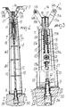
- the device according to the invention comprises at least one pole, generally designated by the reference numeral 1, which has a main structure 2 which can be detachably fixed with its base, by virtue of connection means 3, to a surface of a building 4 which is formed for example by a beam 5.
- the pole 1 has, proximate to its tip, guiding means for a cable element 7 which forms a safety parapet.
- the guiding means are adapted to redirect, in a direction which is substantially parallel to the axis 1a of the pole 1, at least part of the stresses that are transmitted from the cable element 7 to said pole, and the pole 1 has shock-absorbing means 8 for damping the stresses transmitted by the cable element 7 to the pole 1 in a direction which is substantially parallel to the axis 1a of the pole.
- the base of the pole 1 is constituted by a base plate 9 resting with its lower face on the surface 4, and the main structure 2 of the pole is preferably constituted by sections 10, for example having a T-shaped or H-shaped cross-section, which are spaced around the axis 1a of the pole and rigidly connect the base plate 9 to a tip element 11 which constitutes the tip of the pole 1.
- the guiding means comprise guides for the cable element 7 which form, proximate to the tip of the pole, a portion of path of said cable element 7 which has a component which is parallel to the axis 1a of the pole.
- At least one of the guides is mounted on a supporting element 12, which can move with respect to the main structure 2 in a direction which is substantially parallel to the axis 1a.
- the shock-absorbing means 8 are interposed between the main structure 2 and the supporting element 12.
- the guides comprise a pair of lateral pulleys 13a and 13b which are associated with the main structure 2 and are arranged so that their axes 14a and 14b are parallel, substantially at right angles to the axis 1a, and are laterally spaced on opposite sides with respect to the axis 1a.
- the pulleys 13a and 13b are supported, so that they can rotate about their respective axes 14a and 14b, by two pairs of wings 15a and 15b which are associated with the tip element 11. More particularly, two wings 15a are provided, which are arranged side by side and support the pulley 13a, and two wings 15b, also arranged side by side, which support the pulley 15b.
- the wings 15a and 15b are rigidly fixed to the lateral surface of a sleeve 16 which is supported by the tip element 11 so that said sleeve can rotate about its own axis, which coincides with the axis 1a.
- the sleeve 16 can be interposed between an axial shoulder, provided on the outer surface of the tip element 11, and a washer 17 which is locked by means of a screw 18 at the upper end of the tip element 11.
- the sleeve 16 and therefore the pairs of wings 15a and 15b can rotate with respect to the tip element 11 about the axis 1a so as to allow lateral changes of direction of the path for the cable element 7.
- the above cited guides comprise, in addition to the pulleys 13a and 13b, an intermediate pulley 19 which is arranged so that its axis 19a lies parallel to the axes 14a and 14b of the pair of pulleys 13a and 13b and is arranged between the pulleys 13a and 13b. Moreover, the intermediate pulley 19 is spaced from the pair of pulleys 13a and 13b in a direction substantially parallel to the axis 1a in order to guide the cable element 7 from the pair of pulleys 13a and 13b to the intermediate pulley 19 along two path portions, indicated by the arrows 20 and 21, which have a component which is parallel to the axis 1a of the pole.
- the supporting element 12, on which the intermediate pulley 19 is fitted, is supported by the main structure 2 so that it is movable along the axis 1a of the pole, and the shock-absorbing means 8 are interposed between the main structure 2 and the supporting element 12.
- the shock-absorbing means 8 can be constituted, as shown, by a spring 22, for example a helical spring orientated so that its axis is parallel to the axis 1a, or can also be constituted by a hydraulic or pneumatic shock absorber which is interposed between the main structure 2 and the supporting element 12.
- the pole 1 is arranged so that its axis 1a lies substantially vertically or is inclined with respect to the vertical, particularly if it is designed to be an end pole of a row of poles, as shown in Figure 12, and the pulleys 13a and 13b are arranged at a same elevation which is higher than the elevation of the intermediate pulley 19.
- the supporting element 12 is provided with a sleeve 23 whose axis preferably coincides with the axis 1a of the pole and is coupled, so that it is slideable along its own axis, to a coaxial sliding seat 24 which is formed in the tip element 11.
- the spring 22 is fitted around the sleeve 23 and engages, with one of its ends, against a shoulder 25a formed by the supporting element 12 and, with its other end, against a shoulder 25b which is formed by the tip element 11 around the inlet of the sliding seat 24.
- means are provided for delimiting the sliding of the sleeve 23 along the sliding seat 24.
- Said means for delimiting the sliding of the sleeve 23 along the sliding seat 24 comprise a traction element 26 which is accommodated within said sleeve 23 and engages, for example by means of a threaded coupling, the tip element 11.
- the traction element 26 connects the supporting element 12 and the tip element 11 and delimits the sliding of the sleeve 23 away from the tip element 11 produced by the action of the spring 22.
- the sleeve 23 is coupled, in the sliding seat 24, so that it can rotate about its own axis so as to allow the intermediate pulley 19 to rotate, together with the pair of pulleys 13a and 13b, about the axis 1a of the pole in order to allow the cable element 7 to perform any lateral changes in direction.
- means are provided for securing the cable element 7 to the supporting element 12.
- Said securing means are preferably constituted by a screw-type clamping element 27 which couples to a threaded hole 28 formed in the supporting element 12 and can be operated so as to clamp the cable element 7 between the pulley 19 and said clamping element 27.
- the clamping element 27 can be actuated or deactivated according to the requirements, as will become apparent hereinafter.
- the main structure 2 of the pole 1 has a shape which tapers from its base toward its tip.
- connection means 3 comprise an anchoring element 30 which can be fixed to the surface 4 of the building and forms a female seat 31 which lies along an axis which is substantially perpendicular to the surface 4 and has an access opening 32 formed in said surface 4 of the building.
- Said female seat 31 can be detachably coupled to a male-shaped end 33 of a securing element 34 which protrudes from the base of the main structure 2 of the pole 1.
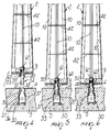
- the female seat 31 has, starting from the access opening 32, a first portion 35, which can be crossed by the male-shaped end 33 which moves axially with respect to the female seat 31, and a second portion 36 which forms, at its end directed toward the first portion 35, at least one axial shoulder 37 which can be engaged by the male-shaped end 33 by a partial rotation of the securing element 34 about the axis of the female seat 31 and by means of an axial translatory motion of the securing element 34 in the opposite direction with respect to the insertion direction relative to the female seat 31.
- the securing element 34 can turn about the axis of the female seat 31 with respect to said female seat 31 through a preset angle, preferably 90°, in order to transfer its male-shaped element 33 from an insertion position, in which it can pass through the first portion 35 and move laterally beyond the axial shoulder 37, to an engagement position, in which it faces, with the male-shaped end 33, the axial shoulder 37.
- the anchoring element 30 is constituted by a tubular body, preferably made of steel, which internally forms the female seat 31.
- Said tubular body has an axial end which is open so as to form the access opening 32 and, in an intermediate region of its extension, at least one raised portion which protrudes from its internal surface and covers a limited arc around the axis of the female seat 31, so as to form said axial shoulder 37.
- the first portion 35 is obtained by means of a compression of the end with the access opening 32 of the tubular body 30 which gives the first portion 35 a non-circular shape.
- the transverse cross-section of the non-circular shape can be, according to the requirements, a rectangular, elliptical, rhomboidal one or another adapted one.
- the compression that forms the first portion 35 at the same time forms the shoulder 37.
- compression is applied to two diametrically opposite regions of the tubular body 30 and forms two axial shoulders 37.
- the second portion 36 of the tubular body 30 preferably has a cylindrical shape.
- the second portion 36 of the tubular body 30 may also be shaped like a cylindrical sector or sectors, so as to allow the male-shaped element 33 to turn in any case about the axis of the tubular body 30 after passing from the first portion 35 to the second portion 36.
- the male-shaped end 33 is shaped complementarily to the first portion 35 of the female seat 31.
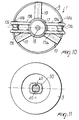
- the male-shaped end 33 is constituted by the lower end of a shaft 40 whose axis lies at right angles to the face of the base plate 9 that rests on the surface 4 and has a diameter which is smaller than the minimum transverse dimension of the first portion 35 of the female seat 31.
- the lower end of the shaft 40 which constitutes the male-shaped end 33, has two lateral protrusions, in two diametrically opposite regions, which form two axial shoulders 41 which can engage the axial shoulders 37 of the female seat 31.
- the locking element 34 is rigidly coupled to the main structure 2 of the pole 1 in rotating about the axis of the female seat 31, and is movable with respect to the main structure 2 along the female seat 31 so as to engage, by means of the axial shoulders 41, against the axial shoulders 37 of the female seat 31 after its male-shaped end 33 has been inserted in the female seat 31 until it lies below the axial shoulders 37 and has been turned through 90° about the axis of said female seat 31.
- the shaft 40 passes, so that it is slideable along its own axis, through a passage 60 which crosses the base plate 9, and the translatory motion of the shaft 40 along the axis of the female seat 31 in order to achieve the engagement of the axial shoulders 41 against the axial shoulders 37 of the female seat 31 can be achieved by providing the upper end of the shaft 40, i.e., its end that lies opposite the male-shaped end 33, so that it is threaded and coupled to an adjustment nut 61 which rests on the upper face of the base plate 9 or in any case against a shoulder formed on the upper face of the base plate 9.
- the main structure 2 of the pole 1 has, on its base, a protrusion 50 which can engage a seat formed in the surface 4 of the building only as a consequence of the insertion of the male-shaped end 33 of the securing element 34 in the female seat 31 and as a consequence of the transfer of the securing element 34 from the insertion position to the engagement position cited above.
- the protrusion 50 lies around the male-shaped end 33 of the securing element 34 and is shaped complementarily to the first portion 35 of the female seat 31.
- the configuration of the protrusion 50 is very similar to the configuration of the male-shaped end 33, but is rotated with respect to it through 90°.
- the protrusion 50 can be formed monolithically or otherwise rigidly coupled to the base plate 9, protruding from the lower face thereof.
- the passage 60 passes through the protrusion 50 and the shaft 40 and is rigidly coupled, in rotation about its own axis, to the protrusion 50 and to the base plate 9.
- the shaft 40 in fact has an axial portion which couples to the passage 60 and has a non-circular transverse cross-section complementary to the transverse shape of the passage 60.
- the portion of the shaft 40 that engages the passage 60 can be, according to the requirements, rectangular, square, splined, star-shaped, or otherwise suitably shaped.
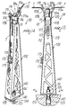
- the device according to the invention comprises at least one pole 101 which is similar to the pole 1 already described with reference to the embodiment shown in the preceding figures.
- the elements of the pole 101 that correspond to the elements of the pole 1 that have already been described have been designated by reference numerals incremented by 100 with respect to the reference numerals of the corresponding elements of pole 1, and for the sake of simplicity only the differences of the pole 101 with respect to the pole 1 are indicated hereinafter.
- the anchoring of the pole 101 to the surface 4 of the building can again be performed by means of an already described anchoring element 30.
- the main structure 102 of the pole 101 is constituted by a lattice-like box-shaped structure which again tapers upwards.
- the internal part of the pole 101 is freer and a membrane-like behavior of the pole 101 in withstanding the stresses applied to it by the cable element 7 is achieved.
- the base of the main structure 102 of the pole 101 constituted by a plate 109, has a rectangular plan shape in order to better utilize the inertia of the pole in the direction in which the cable element 7 pulls, furthermore reducing the space occupation of the base of the pole 101 transversely with respect to the beam 5.
- the pole 101 is provided with means for preventing the accidental disengagement of the cable element 7 with respect to the lateral pulleys 113a and 113b.
- Such means comprise an extension of the pairs of wings 115a and 115b above the pulleys 113a and 113b so as to form two opposite lateral shoulders for the cable element 7.
- the pairs of wings 115a and 115b are also joined, above the pulleys 113a and 113b, by pivots 170 whose axes are parallel to the axes of the pulleys 113a and 113b; said pivots prevent the cable element 7 from climbing over the wings 115a and 115b.
- the means for preventing the disengagement of the cable element 7 with respect to the lateral pulleys 113a and 113b also comprise a central groove 171, in addition to conical flared portions of the cylindrical sides of the pulleys 113a and 113b, adapted to partially accommodate the cable element 7.
- the means for securing the cable element 7 on the intermediate pulley 19 of the embodiment shown in Figures 1 to 12 there are means for securing the cable element 7 on the main structure 102 of the pole 101.
- the securing means comprise a clamp 172 which is associated, for example by means of two screws 173, with the main structure 102 of the pole 101 and can be actuated in order to clamp one end of the cable element 7 to the main structure 102 of the pole 101, thus leaving the intermediate pulley 119 free to rotate.
- both pulleys 113a and 113b can rotate and the shock-absorbing means 108 act symmetrically, centering on the axis of the pole 101 the stresses transmitted to said pole 101 by the cable element 7.
- the pole 101 has means for pre-loading the shock-absorbing means 108.
- the pre-loading means comprise an adjustment screw 174 which is arranged so that its axis is parallel to, or coincides with, the axis 101a of the pole 101 and is supported, so that it is rotatable about its own axis, by the tip element 111 of the pole 101.
- the screw 174 engages a threaded seat formed in the supporting element 112.
- the supporting element 112 is lowered and therefore the pulley 119 is moved away from the pulleys 113a and 113b, extending the spring 122.
- the means for pre-loading the spring 122 can be used to tension the cable element 7 during the assembly of the device, as will become apparent hereinafter.
- the portion of the shaft 140 that engages the passage 160 and the passage 160 have a rectangular or elliptical transverse cross-section, so as to ensure correct orientation of the shaft 140 about its own axis with respect to the protrusion 150 and therefore to the main structure 102 of the pole 101 during the insertion of the pole 140 in the passage 160.
- Installation of the device according to the invention is as follows.
- the poles 1 are installed by using the female seats 31 formed beforehand in the surface 4 during the provision of surface 4 by embedding the tubular body that constitutes the anchoring element 30 in the concrete casting that forms the surface 4.
- the pole 1 is arranged vertically so that the male-shaped end 33 is orientated so that it corresponds to the access opening 32 and can enter the female seat 31 by passing through the first portion 35 and reach the second portion 36, passing beyond the axial shoulders 37.
- the pole 1 is then turned about the axis of the female seat 31 through an angle of 90° (Figure 6), so that the male-shaped end 33 faces, with its axial shoulders 41, the axial shoulders 37. This rotation also causes the insertion of the protrusion 50 in the first portion 35 of the female seat 31, as shown in Figure 7.
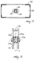
- poles 101 of the type shown in Figures 13 to 18 are installed in a manner similar to the one described with reference to the poles 1.
- a cable element 7 is passed over the pairs of pulleys 13a, 113a and 13b, 113b and under the intermediate pulleys 19, 119 of the various poles 1, 101.
- the cable element 7 is then rigidly coupled to the end poles and tensioned either manually or with the aid of conventional winches.
- One end of the cable element can be coupled to the main structure 2 of an end pole by means of a loop or by means of the clamp 172, while the other end can be anchored to a winch located on the other end pole or secured by means of the clamping element 27, as shown in Figures 1, 12 and 14.
- the cable element 7, with the poles 101 can also be tensioned by pre-loading the springs 122 of the various poles 101 by means of the adjustment screws 174 before securing the ends of the cable element 7 to the end poles 101 or, better still, before passing the cable element 7 over the pulleys 113a, 113b and 119, as shown in Figure 16.
- the springs 122, by virtue of the adjustment screw 174 are partially or fully released, thus tensioning by the required extent the cable element 7 as shown in Figure 17.
- the workers can thus engage their safety harnesses or belts to the portions of the cable element 7 that lie between two contiguous poles.
- the stress produced by the fall is transmitted from the cable element 7 to the various poles and its direction is changed, as a consequence of the particular arrangement of the pulleys 13a, 113a, 13b, 113b and 19, 119, into a direction which has a component which is parallel to the axis of the corresponding pole.
- the change of direction places the shock-absorbing means 8, 108 in their ideal operating conditions.
- the stress transmitted from the cable element 7 to the various poles 1, 101 is adequately damped by the springs 22, 122.
- the compression of the springs 22, 122 also causes an elongation of the portion of the cable element 7 that is affected by the fall, further reducing the jerk transmitted to the worker.
- the shock-absorbing effect provided by the shock-absorbing means 8, 108 the peaks of the stresses discharged by the cable element 7 onto the poles 1, 101 are reduced, and therefore the poles 1, 101 can effectively support the cable element 7 without requiring an excessive oversizing of the end poles.
- the end poles can be inclined outwards so as to offer greater resistance to these stresses.
- the pole 1 instead of being arranged with its axis 1a at right angles to the plane of arrangement of the lower face of the plate 9, 109, lies along an axis which is inclined with respect to the vertical plane that is perpendicular to the lower face of the plate 9, 109.
- poles 1, 101 can be disassembled by fully disengaging the nut 61, 161 from the shaft 40, 140 and then manually extracting the shaft 40, 140 from the female seat 31. The shaft 40, 140 is then assembled manually to the base of the pole 1, 101 before subsequent use of the pole.
- the clamping element 27 arranged on the pole at which the lateral change of direction must occur can be moved to engage the cable element 7 so as to lock it on the intermediate pulley 19.
- the clamping element 27 can also be actuated so as to lock the cable element 7 if one intends to isolate, for example during the disassembly of the safety device, a portion of the cable element 7 from the remaining part of the cable element 7.
- the device according to the invention fully achieves the intended aim, since by virtue of the change in the direction of the cable element along path portions which have a component parallel to the axis of the poles, and by virtue of the use of the shock-absorbing means, it significantly reduces the peaks of the stresses discharged by the cable element onto the poles, eliminating or in any case reducing the need to oversize the poles.
- Another advantage of the device according to the invention is that it allows substantially complete protection of the region to which the device is applied, by virtue of the fact that a direct connection of the cable element to the building is not strictly necessary.
- the materials used, as well as the dimensions, may be any according to requirements and to the state of the art.
Landscapes
- Engineering & Computer Science (AREA)
- Architecture (AREA)
- Mechanical Engineering (AREA)
- Civil Engineering (AREA)
- Structural Engineering (AREA)
- Buildings Adapted To Withstand Abnormal External Influences (AREA)
- On-Site Construction Work That Accompanies The Preparation And Application Of Concrete (AREA)
- Emergency Protection Circuit Devices (AREA)
- Emergency Lowering Means (AREA)
- Building Environments (AREA)
Applications Claiming Priority (2)
| Application Number | Priority Date | Filing Date | Title |
|---|---|---|---|
| IT1999MI001900A IT1313752B1 (it) | 1999-09-09 | 1999-09-09 | Dispositivo antinfortunistico per edifici,particolarmente per ilmontaggio di manufatti prefabbricati in calcestruzzo o simili |
| ITMI991900 | 1999-09-09 |
Publications (3)
| Publication Number | Publication Date |
|---|---|
| EP1083273A2 true EP1083273A2 (de) | 2001-03-14 |
| EP1083273A3 EP1083273A3 (de) | 2002-10-23 |
| EP1083273B1 EP1083273B1 (de) | 2007-05-30 |
Family
ID=11383597
Family Applications (1)
| Application Number | Title | Priority Date | Filing Date |
|---|---|---|---|
| EP00117377A Expired - Lifetime EP1083273B1 (de) | 1999-09-09 | 2000-08-23 | Unfallverhütungsvorrichtung für Gebäude, insbesondere beim Zusammenbauen von vorgefertigten Elementen aus Beton |
Country Status (6)
| Country | Link |
|---|---|
| US (1) | US6412230B1 (de) |
| EP (1) | EP1083273B1 (de) |
| AT (1) | ATE363571T1 (de) |
| DE (1) | DE60035005T2 (de) |
| ES (1) | ES2288821T3 (de) |
| IT (1) | IT1313752B1 (de) |
Cited By (11)
| Publication number | Priority date | Publication date | Assignee | Title |
|---|---|---|---|---|
| GB2373814A (en) * | 2001-02-21 | 2002-10-02 | Shire Precast Erection Ltd | Support for safety apparatus |
| WO2002099226A1 (es) * | 2001-06-04 | 2002-12-12 | Encofrados J. Alsina, S.A. | Dispositivo de seguridad para trabajos sobre superficies horizontales en obras de construccion |
| EP1249564A3 (de) * | 2001-04-12 | 2003-09-10 | Sergio Zambelli | Sicherheitsvorrichtung für das Baugewerbe für die individuelle Absturzsicherung von Arbeitern, die sich in grosser Höhe in sich im Bau befindlichen Gebäuden bewegen |
| GB2413821A (en) * | 2004-05-06 | 2005-11-09 | Stephen Murten | Safety apparatus with overhead connection point |
| WO2006050464A1 (en) * | 2004-11-02 | 2006-05-11 | Purvis, Harrison, G. | Temporary railing for a building including tensioning apparatus and associated methods |
| ES2278480A1 (es) * | 2004-10-14 | 2007-08-01 | Daniel Granados Sanchez | Sistema de seguridad anticaida. |
| WO2006042889A3 (es) * | 2004-10-14 | 2008-06-19 | Sanchez Daniel Granados | Sistema de seguridad anticaída |
| CH700844A1 (de) * | 2009-04-23 | 2010-10-29 | Peter Steiner | Pfosten für ein Sicherheitsgeländer. |
| EP3985209A1 (de) * | 2020-10-16 | 2022-04-20 | Retotub | Pfosten mit anhebesicherung |
| CN114687572A (zh) * | 2022-03-16 | 2022-07-01 | 中建海峡建设发展有限公司 | 一种斜屋面作业生命绳固定装置 |
| WO2022144062A1 (en) * | 2020-12-30 | 2022-07-07 | Crh Concrete A/S | A safety device |
Families Citing this family (27)
| Publication number | Priority date | Publication date | Assignee | Title |
|---|---|---|---|---|
| FR2831826B1 (fr) * | 2001-11-05 | 2004-01-30 | Rodolphe Argoud | Dispositif d'ancrage de securite comportant un amortisseur de choc |
| US6962459B2 (en) * | 2003-08-12 | 2005-11-08 | Sci Products Inc. | Crash attenuator with cable and cylinder arrangement for decelerating vehicles |
| US7104720B2 (en) * | 2003-11-19 | 2006-09-12 | Cyro Industries | Traffic noise barrier system |
| US7546900B2 (en) * | 2004-02-12 | 2009-06-16 | Evonik Cyro Llc | Panel assembly for traffic noise barrier wall |
| US8240431B2 (en) * | 2006-06-16 | 2012-08-14 | Brent Smith | Apparatus for arresting a fall |
| US8157057B1 (en) * | 2007-03-16 | 2012-04-17 | Kenneth Johnson | Safety apparatus for scaffolding |
| US20100301297A1 (en) * | 2009-05-27 | 2010-12-02 | Chapman Patrick M | Method and apparatus for fall prevention |
| WO2011039754A1 (en) * | 2009-10-02 | 2011-04-07 | Mobius Protection Systems Ltd. | Shock absorbing device |
| US8627923B2 (en) * | 2010-01-15 | 2014-01-14 | Garlock Safety Systems Inc. | Tank lifeline system |
| US8584798B2 (en) * | 2010-06-10 | 2013-11-19 | Garlock Safety Systems Inc. | Safety apparatus for arresting a fall of a worker |
| US9010487B2 (en) * | 2010-09-27 | 2015-04-21 | Arthur V. Cruz | Safety line anchoring system |
| US10569111B2 (en) * | 2011-06-23 | 2020-02-25 | Honeywell International Inc. | Posts for use in fall protection |
| NL2007804C2 (nl) * | 2011-11-17 | 2013-05-21 | Roofsecurity Int Gmbh | Valbeveiligingssysteem voor een hellend dak. |
| DE102012105985B4 (de) * | 2012-07-04 | 2016-01-28 | Dws Pohl Gmbh | Vorrichtung zur Sicherung von Personen gegen Absturz |
| US20150224350A1 (en) * | 2014-02-12 | 2015-08-13 | Michael Harvey | Safety harness anchoring system |
| US10195734B2 (en) * | 2014-06-12 | 2019-02-05 | Western Construction Group, Inc. | Tool stabilizer and methods of assembling the same |
| US9675824B2 (en) | 2015-05-14 | 2017-06-13 | Charles J. Mackarvich | Fall rescue apparatus |
| US9909271B2 (en) | 2015-11-12 | 2018-03-06 | Rite-Hite Holding Corporation | Shock absorbing retractable bollard systems |
| US10456608B2 (en) * | 2016-02-08 | 2019-10-29 | Garlock Safety Systems Inc. | Safety apparatus for arresting a fall of a worker |
| DE102016106533A1 (de) | 2016-04-08 | 2017-10-12 | Bornack Gmbh & Co. Kg | Sicherungssäule |
| GB2550354B (en) * | 2016-05-16 | 2019-04-03 | Absolute Museum & Gallery Products Ltd | A barrier stand |
| DE102017008481A1 (de) * | 2017-09-08 | 2019-03-14 | Fiona Gabriella Saygivar | Absturzsicherung mit Standsockel |
| US10767325B2 (en) | 2018-01-05 | 2020-09-08 | Superior Transparent Noise Barriers LLC | Impact absorbing traffic noise barrier system |
| US10695594B2 (en) * | 2018-04-25 | 2020-06-30 | Anchor Ring Solutions, Llc | Safety anchor apparatus |
| US11484735B2 (en) * | 2018-09-24 | 2022-11-01 | Jonathan Wade WILSON | Fall protection cable system for roofing installation on steel buildings and method of use and installation thereof |
| US11167782B1 (en) | 2020-12-30 | 2021-11-09 | Charles J. Mackarvich | Fall arrest cart |
| US20230021139A1 (en) * | 2021-07-19 | 2023-01-19 | Nawar Kzeer | Roof Anchor |
Citations (1)
| Publication number | Priority date | Publication date | Assignee | Title |
|---|---|---|---|---|
| US4045003A (en) | 1973-03-14 | 1977-08-30 | Mccluskey John R | Support devices for stanchions |
Family Cites Families (16)
| Publication number | Priority date | Publication date | Assignee | Title |
|---|---|---|---|---|
| US1633112A (en) * | 1924-12-11 | 1927-06-21 | Kulbeck Niels | Scaffold |
| US1713956A (en) * | 1925-08-04 | 1929-05-21 | Babcock & Wilcox Co | Boiler platform |
| US2237543A (en) * | 1940-01-29 | 1941-04-08 | Hubert C Berchem | Adjustable extension scaffold trestle with guard rail |
| US2725853A (en) * | 1952-07-05 | 1955-12-06 | Nordheim Jonas | Tethering devices |
| US3880405A (en) * | 1974-01-18 | 1975-04-29 | Butler Manufacturing Co | Portable, personnel guard rail |
| US4598503A (en) * | 1984-06-04 | 1986-07-08 | Berger Richard C | Vibration absorption mounting for a rooftop air handling unit or the like (II) |
| US5029670A (en) * | 1990-06-22 | 1991-07-09 | Whitmer Gerald T | Frame erection safety system and components thereof |
| WO1994008658A1 (en) * | 1992-10-14 | 1994-04-28 | Rose Systems, Inc. | Safety apparatus |
| US5358068A (en) * | 1992-10-30 | 1994-10-25 | Whitmer Gerald T | Safety system including cable tensioner and shock absorber |
| US5398777A (en) * | 1992-11-05 | 1995-03-21 | Sinco Acquisition Corporation | Lifeline anchor assembly for pre-cast concrete deck |
| US5297651A (en) * | 1993-04-28 | 1994-03-29 | Swingstage Limited | Safety load transfer device and system |
| US5350037A (en) * | 1993-05-24 | 1994-09-27 | Skymaster, Inc. | Workperson safety restraint system |
| US5699875A (en) * | 1995-10-31 | 1997-12-23 | Spancrete Industries, Inc. | Lifeline anchor |
| GB9702611D0 (en) * | 1997-02-08 | 1997-03-26 | W F Price Roofing Limited | Safety barrier system |
| FR2774297B1 (fr) * | 1998-02-05 | 2000-04-14 | Somain | Dispositif de securite notamment pour toiture de batiment |
| DE29820579U1 (de) * | 1998-11-18 | 1999-02-04 | Fa. Herbert Bornack, 74080 Heilbronn | Absturzsicherung auf Flachdächern, Plattformen u.dgl. |
-
1999
- 1999-09-09 IT IT1999MI001900A patent/IT1313752B1/it active
-
2000
- 2000-08-23 ES ES00117377T patent/ES2288821T3/es not_active Expired - Lifetime
- 2000-08-23 AT AT00117377T patent/ATE363571T1/de not_active IP Right Cessation
- 2000-08-23 EP EP00117377A patent/EP1083273B1/de not_active Expired - Lifetime
- 2000-08-23 DE DE60035005T patent/DE60035005T2/de not_active Expired - Lifetime
- 2000-08-24 US US09/645,560 patent/US6412230B1/en not_active Expired - Fee Related
Patent Citations (1)
| Publication number | Priority date | Publication date | Assignee | Title |
|---|---|---|---|---|
| US4045003A (en) | 1973-03-14 | 1977-08-30 | Mccluskey John R | Support devices for stanchions |
Cited By (20)
| Publication number | Priority date | Publication date | Assignee | Title |
|---|---|---|---|---|
| GB2373814B (en) * | 2001-02-21 | 2004-09-29 | Shire Precast Erection Ltd | Safety apparatus and a support therefor |
| GB2373814A (en) * | 2001-02-21 | 2002-10-02 | Shire Precast Erection Ltd | Support for safety apparatus |
| EP1249564A3 (de) * | 2001-04-12 | 2003-09-10 | Sergio Zambelli | Sicherheitsvorrichtung für das Baugewerbe für die individuelle Absturzsicherung von Arbeitern, die sich in grosser Höhe in sich im Bau befindlichen Gebäuden bewegen |
| US6715238B2 (en) | 2001-04-12 | 2004-04-06 | Sergio Zambelli | Fall protecting safety device |
| RU2286431C2 (ru) * | 2001-06-04 | 2006-10-27 | Энкофрадос Х. Альсина, С.А. | Устройство для безопасной работы на горизонтальных поверхностях строящихся объектов |
| WO2002099226A1 (es) * | 2001-06-04 | 2002-12-12 | Encofrados J. Alsina, S.A. | Dispositivo de seguridad para trabajos sobre superficies horizontales en obras de construccion |
| ES2178610A1 (es) * | 2001-06-04 | 2002-12-16 | Encofrados J Alsina Sa | Dispositivo de seguridad para trabajos sobre superficies horizontales en obras de construccion. |
| GB2413821A (en) * | 2004-05-06 | 2005-11-09 | Stephen Murten | Safety apparatus with overhead connection point |
| ES2294889A1 (es) * | 2004-10-14 | 2008-04-01 | Daniel Granados Sanchez | Adicion a la patente 200402434 por "sistema de seguridad anticaida". |
| ES2278480A1 (es) * | 2004-10-14 | 2007-08-01 | Daniel Granados Sanchez | Sistema de seguridad anticaida. |
| ES2278480B1 (es) * | 2004-10-14 | 2008-05-16 | Daniel Granados Sanchez | Sistema de seguridad anticaida. |
| WO2006042889A3 (es) * | 2004-10-14 | 2008-06-19 | Sanchez Daniel Granados | Sistema de seguridad anticaída |
| ES2294889B1 (es) * | 2004-10-14 | 2008-11-16 | Daniel Granados Sanchez | Adicion a la patente 200402434 por "sistema de seguridad anticaida". |
| WO2006050464A1 (en) * | 2004-11-02 | 2006-05-11 | Purvis, Harrison, G. | Temporary railing for a building including tensioning apparatus and associated methods |
| CH700844A1 (de) * | 2009-04-23 | 2010-10-29 | Peter Steiner | Pfosten für ein Sicherheitsgeländer. |
| EP3985209A1 (de) * | 2020-10-16 | 2022-04-20 | Retotub | Pfosten mit anhebesicherung |
| FR3115310A1 (fr) * | 2020-10-16 | 2022-04-22 | Retotub | Poteau comportant un système anti-soulèvement |
| WO2022144062A1 (en) * | 2020-12-30 | 2022-07-07 | Crh Concrete A/S | A safety device |
| US12227394B2 (en) | 2020-12-30 | 2025-02-18 | Crh Concrete A/S | Safety device |
| CN114687572A (zh) * | 2022-03-16 | 2022-07-01 | 中建海峡建设发展有限公司 | 一种斜屋面作业生命绳固定装置 |
Also Published As
| Publication number | Publication date |
|---|---|
| ATE363571T1 (de) | 2007-06-15 |
| DE60035005T2 (de) | 2008-02-07 |
| ITMI991900A1 (it) | 2001-03-09 |
| US6412230B1 (en) | 2002-07-02 |
| EP1083273A3 (de) | 2002-10-23 |
| EP1083273B1 (de) | 2007-05-30 |
| IT1313752B1 (it) | 2002-09-17 |
| ITMI991900A0 (it) | 1999-09-09 |
| ES2288821T3 (es) | 2008-02-01 |
| DE60035005D1 (de) | 2007-07-12 |
Similar Documents
| Publication | Publication Date | Title |
|---|---|---|
| EP1083273B1 (de) | Unfallverhütungsvorrichtung für Gebäude, insbesondere beim Zusammenbauen von vorgefertigten Elementen aus Beton | |
| US6779630B2 (en) | Rebar stanchion horizontal lifeline fall arrest system | |
| US20030033760A1 (en) | Foundation support for manufactured homes | |
| US20100243837A1 (en) | Anchor point | |
| WO2005061817A1 (en) | Safety device for a fall restraint | |
| CA2379448A1 (en) | Safety device for the building field, for individually protecting against falls workers assigned to walking at high elevations in buildings under construction | |
| WO2002029162B1 (en) | Improved guardrail terminals | |
| KR102652447B1 (ko) | 철근 배치구조 조정이 가능한 철근 일체화 스마트 정착장치를 이용한 무용접 철근 정착방법 | |
| KR101805361B1 (ko) | 안전난간용 철골고정 클램프 | |
| KR20120001521U (ko) | 생명줄 전용 안전 난간대 | |
| EP2213810B1 (de) | Vorrichtung für Sicherheitsleine | |
| CN108951888B (zh) | 装配式墙体连接装置及其连接方法 | |
| JP7540803B1 (ja) | 衝撃吸収柵 | |
| KR102607257B1 (ko) | 배전용 전신주의 전선 지지장치 | |
| KR200277941Y1 (ko) | 건축용 동바리 | |
| KR102615345B1 (ko) | 건축용 석재 고정장치 | |
| EP1156169B1 (de) | Stützvorrichtung für vorgefertigt, insbesondere aus Beton oder ähnlichem, hergestellte Gebäudeteile mit hohem Widerstand gegen Erdbeben | |
| KR102197343B1 (ko) | 텐던 인장형 고성능 울타리 구조물 | |
| JP2005282244A (ja) | 防護柵 | |
| KR102197345B1 (ko) | 고성능 목재 방호 울타리 | |
| CN208981233U (zh) | 一种急转弯护栏 | |
| KR200209566Y1 (ko) | 건축용 동바리 | |
| CN115726358B (zh) | 一种装配式钢管桩固定装置 | |
| KR100556624B1 (ko) | 동바리 조립용 브라켓과 이를 이용한 동바리 시스템 | |
| KR100757274B1 (ko) | 다기능성 강선형 비계 |
Legal Events
| Date | Code | Title | Description |
|---|---|---|---|
| PUAI | Public reference made under article 153(3) epc to a published international application that has entered the european phase |
Free format text: ORIGINAL CODE: 0009012 |
|
| AK | Designated contracting states |
Kind code of ref document: A2 Designated state(s): AT BE CH CY DE DK ES FI FR GB GR IE IT LI LU MC NL PT SE |
|
| AX | Request for extension of the european patent |
Free format text: AL;LT;LV;MK;RO;SI |
|
| PUAL | Search report despatched |
Free format text: ORIGINAL CODE: 0009013 |
|
| AK | Designated contracting states |
Kind code of ref document: A3 Designated state(s): AT BE CH CY DE DK ES FI FR GB GR IE IT LI LU MC NL PT SE |
|
| AX | Request for extension of the european patent |
Free format text: AL;LT;LV;MK;RO;SI |
|
| 17P | Request for examination filed |
Effective date: 20030410 |
|
| AKX | Designation fees paid |
Designated state(s): AT BE CH CY DE DK ES FI FR GB GR IE IT LI LU MC NL PT SE |
|
| 17Q | First examination report despatched |
Effective date: 20050623 |
|
| GRAP | Despatch of communication of intention to grant a patent |
Free format text: ORIGINAL CODE: EPIDOSNIGR1 |
|
| GRAS | Grant fee paid |
Free format text: ORIGINAL CODE: EPIDOSNIGR3 |
|
| GRAA | (expected) grant |
Free format text: ORIGINAL CODE: 0009210 |
|
| AK | Designated contracting states |
Kind code of ref document: B1 Designated state(s): AT BE CH CY DE DK ES FI FR GB GR IE IT LI LU MC NL PT SE |
|
| PG25 | Lapsed in a contracting state [announced via postgrant information from national office to epo] |
Ref country code: CH Free format text: LAPSE BECAUSE OF FAILURE TO SUBMIT A TRANSLATION OF THE DESCRIPTION OR TO PAY THE FEE WITHIN THE PRESCRIBED TIME-LIMIT Effective date: 20070530 Ref country code: LI Free format text: LAPSE BECAUSE OF FAILURE TO SUBMIT A TRANSLATION OF THE DESCRIPTION OR TO PAY THE FEE WITHIN THE PRESCRIBED TIME-LIMIT Effective date: 20070530 Ref country code: FI Free format text: LAPSE BECAUSE OF FAILURE TO SUBMIT A TRANSLATION OF THE DESCRIPTION OR TO PAY THE FEE WITHIN THE PRESCRIBED TIME-LIMIT Effective date: 20070530 |
|
| REG | Reference to a national code |
Ref country code: GB Ref legal event code: FG4D |
|
| REG | Reference to a national code |
Ref country code: CH Ref legal event code: EP |
|
| REG | Reference to a national code |
Ref country code: IE Ref legal event code: FG4D |
|
| REF | Corresponds to: |
Ref document number: 60035005 Country of ref document: DE Date of ref document: 20070712 Kind code of ref document: P |
|
| PG25 | Lapsed in a contracting state [announced via postgrant information from national office to epo] |
Ref country code: SE Free format text: LAPSE BECAUSE OF FAILURE TO SUBMIT A TRANSLATION OF THE DESCRIPTION OR TO PAY THE FEE WITHIN THE PRESCRIBED TIME-LIMIT Effective date: 20070830 |
|
| ET | Fr: translation filed | ||
| PG25 | Lapsed in a contracting state [announced via postgrant information from national office to epo] |
Ref country code: AT Free format text: LAPSE BECAUSE OF FAILURE TO SUBMIT A TRANSLATION OF THE DESCRIPTION OR TO PAY THE FEE WITHIN THE PRESCRIBED TIME-LIMIT Effective date: 20070530 |
|
| NLV1 | Nl: lapsed or annulled due to failure to fulfill the requirements of art. 29p and 29m of the patents act | ||
| REG | Reference to a national code |
Ref country code: CH Ref legal event code: PL |
|
| PG25 | Lapsed in a contracting state [announced via postgrant information from national office to epo] |
Ref country code: BE Free format text: LAPSE BECAUSE OF FAILURE TO SUBMIT A TRANSLATION OF THE DESCRIPTION OR TO PAY THE FEE WITHIN THE PRESCRIBED TIME-LIMIT Effective date: 20070530 |
|
| PG25 | Lapsed in a contracting state [announced via postgrant information from national office to epo] |
Ref country code: DK Free format text: LAPSE BECAUSE OF FAILURE TO SUBMIT A TRANSLATION OF THE DESCRIPTION OR TO PAY THE FEE WITHIN THE PRESCRIBED TIME-LIMIT Effective date: 20070530 Ref country code: NL Free format text: LAPSE BECAUSE OF FAILURE TO SUBMIT A TRANSLATION OF THE DESCRIPTION OR TO PAY THE FEE WITHIN THE PRESCRIBED TIME-LIMIT Effective date: 20070530 Ref country code: PT Free format text: LAPSE BECAUSE OF FAILURE TO SUBMIT A TRANSLATION OF THE DESCRIPTION OR TO PAY THE FEE WITHIN THE PRESCRIBED TIME-LIMIT Effective date: 20071030 |
|
| REG | Reference to a national code |
Ref country code: ES Ref legal event code: FG2A Ref document number: 2288821 Country of ref document: ES Kind code of ref document: T3 |
|
| PLBE | No opposition filed within time limit |
Free format text: ORIGINAL CODE: 0009261 |
|
| STAA | Information on the status of an ep patent application or granted ep patent |
Free format text: STATUS: NO OPPOSITION FILED WITHIN TIME LIMIT |
|
| GBPC | Gb: european patent ceased through non-payment of renewal fee |
Effective date: 20070830 |
|
| PG25 | Lapsed in a contracting state [announced via postgrant information from national office to epo] |
Ref country code: GR Free format text: LAPSE BECAUSE OF FAILURE TO SUBMIT A TRANSLATION OF THE DESCRIPTION OR TO PAY THE FEE WITHIN THE PRESCRIBED TIME-LIMIT Effective date: 20070831 Ref country code: MC Free format text: LAPSE BECAUSE OF NON-PAYMENT OF DUE FEES Effective date: 20070831 |
|
| 26N | No opposition filed |
Effective date: 20080303 |
|
| PG25 | Lapsed in a contracting state [announced via postgrant information from national office to epo] |
Ref country code: IE Free format text: LAPSE BECAUSE OF NON-PAYMENT OF DUE FEES Effective date: 20070823 |
|
| PG25 | Lapsed in a contracting state [announced via postgrant information from national office to epo] |
Ref country code: GB Free format text: LAPSE BECAUSE OF NON-PAYMENT OF DUE FEES Effective date: 20070830 |
|
| PG25 | Lapsed in a contracting state [announced via postgrant information from national office to epo] |
Ref country code: CY Free format text: LAPSE BECAUSE OF FAILURE TO SUBMIT A TRANSLATION OF THE DESCRIPTION OR TO PAY THE FEE WITHIN THE PRESCRIBED TIME-LIMIT Effective date: 20070530 |
|
| PG25 | Lapsed in a contracting state [announced via postgrant information from national office to epo] |
Ref country code: LU Free format text: LAPSE BECAUSE OF NON-PAYMENT OF DUE FEES Effective date: 20070823 |
|
| PGFP | Annual fee paid to national office [announced via postgrant information from national office to epo] |
Ref country code: DE Payment date: 20110201 Year of fee payment: 11 Ref country code: FR Payment date: 20110211 Year of fee payment: 11 |
|
| PGFP | Annual fee paid to national office [announced via postgrant information from national office to epo] |
Ref country code: ES Payment date: 20110128 Year of fee payment: 11 |
|
| REG | Reference to a national code |
Ref country code: FR Ref legal event code: ST Effective date: 20120430 |
|
| REG | Reference to a national code |
Ref country code: DE Ref legal event code: R119 Ref document number: 60035005 Country of ref document: DE Effective date: 20120301 |
|
| PG25 | Lapsed in a contracting state [announced via postgrant information from national office to epo] |
Ref country code: FR Free format text: LAPSE BECAUSE OF NON-PAYMENT OF DUE FEES Effective date: 20110831 |
|
| PG25 | Lapsed in a contracting state [announced via postgrant information from national office to epo] |
Ref country code: DE Free format text: LAPSE BECAUSE OF NON-PAYMENT OF DUE FEES Effective date: 20120301 |
|
| REG | Reference to a national code |
Ref country code: ES Ref legal event code: FD2A Effective date: 20130823 |
|
| PG25 | Lapsed in a contracting state [announced via postgrant information from national office to epo] |
Ref country code: ES Free format text: LAPSE BECAUSE OF NON-PAYMENT OF DUE FEES Effective date: 20110824 |
|
| PGFP | Annual fee paid to national office [announced via postgrant information from national office to epo] |
Ref country code: IT Payment date: 20130827 Year of fee payment: 14 |
|
| PG25 | Lapsed in a contracting state [announced via postgrant information from national office to epo] |
Ref country code: IT Free format text: LAPSE BECAUSE OF NON-PAYMENT OF DUE FEES Effective date: 20140823 |