EP1083331A2 - Dispositif d'alimentation en carburant d'un moteur à combustion d'un véhicule à partir d'un réservoir - Google Patents
Dispositif d'alimentation en carburant d'un moteur à combustion d'un véhicule à partir d'un réservoir Download PDFInfo
- Publication number
- EP1083331A2 EP1083331A2 EP00116671A EP00116671A EP1083331A2 EP 1083331 A2 EP1083331 A2 EP 1083331A2 EP 00116671 A EP00116671 A EP 00116671A EP 00116671 A EP00116671 A EP 00116671A EP 1083331 A2 EP1083331 A2 EP 1083331A2
- Authority
- EP
- European Patent Office
- Prior art keywords
- pressure
- fuel
- line
- return line
- fuel tank
- Prior art date
- Legal status (The legal status is an assumption and is not a legal conclusion. Google has not performed a legal analysis and makes no representation as to the accuracy of the status listed.)
- Granted
Links
Images
Classifications
-
- F—MECHANICAL ENGINEERING; LIGHTING; HEATING; WEAPONS; BLASTING
- F02—COMBUSTION ENGINES; HOT-GAS OR COMBUSTION-PRODUCT ENGINE PLANTS
- F02M—SUPPLYING COMBUSTION ENGINES IN GENERAL WITH COMBUSTIBLE MIXTURES OR CONSTITUENTS THEREOF
- F02M37/00—Apparatus or systems for feeding liquid fuel from storage containers to carburettors or fuel-injection apparatus; Arrangements for purifying liquid fuel specially adapted for, or arranged on, internal-combustion engines
- F02M37/0047—Layout or arrangement of systems for feeding fuel
- F02M37/0052—Details on the fuel return circuit; Arrangement of pressure regulators
-
- B—PERFORMING OPERATIONS; TRANSPORTING
- B60—VEHICLES IN GENERAL
- B60K—ARRANGEMENT OR MOUNTING OF PROPULSION UNITS OR OF TRANSMISSIONS IN VEHICLES; ARRANGEMENT OR MOUNTING OF PLURAL DIVERSE PRIME-MOVERS IN VEHICLES; AUXILIARY DRIVES FOR VEHICLES; INSTRUMENTATION OR DASHBOARDS FOR VEHICLES; ARRANGEMENTS IN CONNECTION WITH COOLING, AIR INTAKE, GAS EXHAUST OR FUEL SUPPLY OF PROPULSION UNITS IN VEHICLES
- B60K15/00—Arrangement in connection with fuel supply of combustion engines or other fuel consuming energy converters, e.g. fuel cells; Mounting or construction of fuel tanks
- B60K15/01—Arrangement of fuel conduits
-
- F—MECHANICAL ENGINEERING; LIGHTING; HEATING; WEAPONS; BLASTING
- F02—COMBUSTION ENGINES; HOT-GAS OR COMBUSTION-PRODUCT ENGINE PLANTS
- F02M—SUPPLYING COMBUSTION ENGINES IN GENERAL WITH COMBUSTIBLE MIXTURES OR CONSTITUENTS THEREOF
- F02M37/00—Apparatus or systems for feeding liquid fuel from storage containers to carburettors or fuel-injection apparatus; Arrangements for purifying liquid fuel specially adapted for, or arranged on, internal-combustion engines
- F02M37/02—Feeding by means of suction apparatus, e.g. by air flow through carburettors
- F02M37/025—Feeding by means of a liquid fuel-driven jet pump
-
- F—MECHANICAL ENGINEERING; LIGHTING; HEATING; WEAPONS; BLASTING
- F02—COMBUSTION ENGINES; HOT-GAS OR COMBUSTION-PRODUCT ENGINE PLANTS
- F02D—CONTROLLING COMBUSTION ENGINES
- F02D33/00—Controlling delivery of fuel or combustion-air, not otherwise provided for
- F02D33/003—Controlling the feeding of liquid fuel from storage containers to carburettors or fuel-injection apparatus ; Failure or leakage prevention; Diagnosis or detection of failure; Arrangement of sensors in the fuel system; Electric wiring; Electrostatic discharge
- F02D33/006—Controlling the feeding of liquid fuel from storage containers to carburettors or fuel-injection apparatus ; Failure or leakage prevention; Diagnosis or detection of failure; Arrangement of sensors in the fuel system; Electric wiring; Electrostatic discharge depending on engine operating conditions, e.g. start, stop or ambient conditions
-
- F—MECHANICAL ENGINEERING; LIGHTING; HEATING; WEAPONS; BLASTING
- F02—COMBUSTION ENGINES; HOT-GAS OR COMBUSTION-PRODUCT ENGINE PLANTS
- F02M—SUPPLYING COMBUSTION ENGINES IN GENERAL WITH COMBUSTIBLE MIXTURES OR CONSTITUENTS THEREOF
- F02M37/00—Apparatus or systems for feeding liquid fuel from storage containers to carburettors or fuel-injection apparatus; Arrangements for purifying liquid fuel specially adapted for, or arranged on, internal-combustion engines
- F02M37/0076—Details of the fuel feeding system related to the fuel tank
- F02M37/0082—Devices inside the fuel tank other than fuel pumps or filters
-
- F—MECHANICAL ENGINEERING; LIGHTING; HEATING; WEAPONS; BLASTING
- F02—COMBUSTION ENGINES; HOT-GAS OR COMBUSTION-PRODUCT ENGINE PLANTS
- F02M—SUPPLYING COMBUSTION ENGINES IN GENERAL WITH COMBUSTIBLE MIXTURES OR CONSTITUENTS THEREOF
- F02M37/00—Apparatus or systems for feeding liquid fuel from storage containers to carburettors or fuel-injection apparatus; Arrangements for purifying liquid fuel specially adapted for, or arranged on, internal-combustion engines
- F02M37/04—Feeding by means of driven pumps
- F02M37/08—Feeding by means of driven pumps electrically driven
- F02M37/10—Feeding by means of driven pumps electrically driven submerged in fuel, e.g. in reservoir
- F02M37/106—Feeding by means of driven pumps electrically driven submerged in fuel, e.g. in reservoir the pump being installed in a sub-tank
Definitions
- the invention relates to a fuel delivery from a fuel tank to an internal combustion engine of a motor vehicle provided conveyor a feed pump, and with means for controlling a Pressure within one from the feed pump to the internal combustion engine led flow line.
- Such a conveyor has control means of pressure between the supply line and one from the engine into the fuel tank Recirculated return line arranged throttle and is known from practice.
- Pressure in the flow line should be ensured that with a high power consumption of the internal combustion engine a high pressure and a low pressure at start prevails in the supply line.
- a high pressure and a low pressure at start prevails in the supply line.
- a disadvantage of the known conveyor is that the throttle particularly in the high-load range of the internal combustion engine a proposed high pressure in the Supply line often cannot hold reliably because Fuel from the supply line via the throttle into the flows over a low pressure return line.
- the invention is based on the problem of a conveyor of the type mentioned in such a way that they maintain a particularly precise pressure within the flow line enables.
- a branch connected to the flow line for Pumping fuel from one chamber to another Chamber provided suction jet pump arranged.
- suction jet pump a promotion of the suction jet pump can be reliable make sure if within the return line Mixer to mix the flowing back through the return line Fuel with branched off from the supply line, provided to supply a suction jet pump Fuel is arranged.
- the suction jet pump also creates a back pressure in the return line, so that the control of the pressure control valve and thus the in pressure in the supply line is particularly precise.
- the arrangement of the invention Pressure control valve in the flow line that at a high fuel consumption by the internal combustion engine or a low delivery rate of the feed pump in particular little fuel through the branch in the fuel tank drains away.
- a planned maximum pressure in the flow line leaves according to another advantageous development of the Adhere to the invention particularly reliably if the Flow line with one provided above one Pressure opening, connecting to the fuel tank having pressure relief valve is connected.
- Emissions of fuel into the environment can be according to another advantageous development of Keep the invention particularly low if the pressure relief valve, the pressure control valve and the check valve for placement inside the fuel tank are provided. As a result, all connections are Conveyor device according to the invention within the fuel tank arranged so that leaks do not lead to fuel leakage.
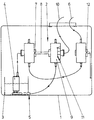
- the drawing shows schematically in a single figure one according to the invention in a fuel tank 1 arranged conveyor 2 for diesel fuel.
- the Conveyor 2 has one in a baffle 3 of the Fuel tank 1 arranged feed pump 4.
- the Swirl pot 3 is arranged over a in the bottom area Suction jet pump 5 filled with fuel.
- the feed pump 4 delivers fuel via a feed line 6 to a Internal combustion engine, not shown.
- In the lead pipe 6 is a by means of a pressure control valve 7 closable, leading to the suction jet pump 5 Branch 8 arranged.
- Via the branch 8 of the Flow line 6 fuel removed in a mixer 9 with fuel from one of the internal combustion engine in the fuel tank 1 returned return line 10 mixed.
- connection of the return line 10 to the Mixer 9 has a check valve 11, which at a provided pressure difference between the mixer 9 and the return line 10 closes. Furthermore, in the Flow line 6 a pressure relief valve 12 is arranged. Above a specified pressure in the flow line 6 opens this and allows the Fuel into the fuel tank 1.
Landscapes
- Engineering & Computer Science (AREA)
- Chemical & Material Sciences (AREA)
- Combustion & Propulsion (AREA)
- Mechanical Engineering (AREA)
- General Engineering & Computer Science (AREA)
- Sustainable Development (AREA)
- Life Sciences & Earth Sciences (AREA)
- Sustainable Energy (AREA)
- Transportation (AREA)
- Fuel-Injection Apparatus (AREA)
- Jet Pumps And Other Pumps (AREA)
- Cooling, Air Intake And Gas Exhaust, And Fuel Tank Arrangements In Propulsion Units (AREA)
- Output Control And Ontrol Of Special Type Engine (AREA)
- Arrangement Or Mounting Of Propulsion Units For Vehicles (AREA)
Applications Claiming Priority (2)
| Application Number | Priority Date | Filing Date | Title |
|---|---|---|---|
| DE19942548 | 1999-09-07 | ||
| DE19942548A DE19942548A1 (de) | 1999-09-07 | 1999-09-07 | Zum Fördern von Kraftstoff aus einem Kraftstoffbehälter zu einer Brennkraftmaschine eines Kraftfahrzeuges vorgesehene Fördereinrichtung |
Publications (3)
| Publication Number | Publication Date |
|---|---|
| EP1083331A2 true EP1083331A2 (fr) | 2001-03-14 |
| EP1083331A3 EP1083331A3 (fr) | 2001-10-31 |
| EP1083331B1 EP1083331B1 (fr) | 2005-06-01 |
Family
ID=7921019
Family Applications (1)
| Application Number | Title | Priority Date | Filing Date |
|---|---|---|---|
| EP00116671A Expired - Lifetime EP1083331B1 (fr) | 1999-09-07 | 2000-08-02 | Dispositif d'alimentation en carburant d'un moteur à combustion d'un véhicule à partir d'un réservoir |
Country Status (8)
| Country | Link |
|---|---|
| US (1) | US6422204B1 (fr) |
| EP (1) | EP1083331B1 (fr) |
| JP (1) | JP4755329B2 (fr) |
| KR (1) | KR100833353B1 (fr) |
| AT (1) | ATE296951T1 (fr) |
| AU (1) | AU5189100A (fr) |
| BR (1) | BR0003998A (fr) |
| DE (2) | DE19942548A1 (fr) |
Families Citing this family (2)
| Publication number | Priority date | Publication date | Assignee | Title |
|---|---|---|---|---|
| DE602007013323D1 (de) | 2006-08-16 | 2011-05-05 | Honda Motor Co Ltd | Kraftstoffzufuhrsystem für einen Allzweckmotor |
| US8820298B2 (en) * | 2009-12-07 | 2014-09-02 | Denso International America, Inc. | Passive and semi-active diesel and gasoline fuel module |
Family Cites Families (27)
| Publication number | Priority date | Publication date | Assignee | Title |
|---|---|---|---|---|
| US2653543A (en) * | 1950-05-03 | 1953-09-29 | Hobson Ltd H M | Hydraulic pump |
| US4617116A (en) * | 1984-05-04 | 1986-10-14 | Ford Motor Company | Automotive type fuel feed system |
| JPH0681933B2 (ja) * | 1986-03-13 | 1994-10-19 | 日本電装株式会社 | 燃料供給ポンプ装置 |
| JP2508693B2 (ja) * | 1987-03-16 | 1996-06-19 | 日本電装株式会社 | 車両用燃料供給装置 |
| US4780063A (en) * | 1987-10-09 | 1988-10-25 | Walbro Corporation | Vehicle fuel pump having a noise-reduction jacket |
| US4926829A (en) * | 1988-11-28 | 1990-05-22 | Walbro Corporation | Pressure-responsive fuel delivery system |
| JPH02153253A (ja) * | 1988-12-05 | 1990-06-12 | Mitsuba Electric Mfg Co Ltd | 燃料供給装置 |
| JPH089420Y2 (ja) * | 1989-07-13 | 1996-03-21 | トヨタ自動車株式会社 | 燃料タンクの燃料移送装置 |
| JP2596150B2 (ja) * | 1989-12-13 | 1997-04-02 | 日産自動車株式会社 | 車両用燃料タンクのエゼクタポンプ |
| JP2527348Y2 (ja) * | 1990-09-19 | 1997-02-26 | 株式会社ユニシアジェックス | 車両用燃料タンク |
| WO1992006286A1 (fr) * | 1990-10-05 | 1992-04-16 | Nippondenso Co., Ltd. | Dispositif de commande de preinjection |
| DE4117813A1 (de) * | 1991-05-31 | 1992-12-03 | Bosch Gmbh Robert | Kraftstoffeinspritzpumpe fuer brennkraftmaschinen |
| US5207203A (en) * | 1992-03-23 | 1993-05-04 | General Motors Corporation | Fuel system |
| US5341842A (en) * | 1993-07-12 | 1994-08-30 | Ford Motor Company | Bottom mount fuel tank module for an automobile |
| JP2874082B2 (ja) * | 1993-09-10 | 1999-03-24 | 三菱自動車工業株式会社 | 内燃機関用燃料供給装置 |
| JPH08319865A (ja) * | 1995-05-26 | 1996-12-03 | Mitsubishi Motors Corp | 筒内噴射式内燃機関における燃料噴射制御装置 |
| US5558067A (en) * | 1995-08-24 | 1996-09-24 | Cummins Engine Company, Inc. | Double pulsing electronic unit injector solenoid valve to fill timing chamber before metering chamber |
| DE19540892A1 (de) * | 1995-11-02 | 1997-05-07 | Bayerische Motoren Werke Ag | Kraftstoffanlage |
| DE19607070B4 (de) * | 1996-02-24 | 2013-04-25 | Robert Bosch Gmbh | Verfahren und Vorrichtung zur Steuerung einer Brennkraftmaschine |
| DE19618707C2 (de) * | 1996-05-09 | 1998-12-17 | Siemens Ag | Verfahren und Vorrichtung zur Regelung eines Kraftstoffvolumenstromes |
| JP3216539B2 (ja) * | 1996-09-10 | 2001-10-09 | トヨタ自動車株式会社 | 内燃機関の燃料供給装置 |
| JP3552457B2 (ja) * | 1997-04-21 | 2004-08-11 | 三菱自動車エンジニアリング株式会社 | 合流装置 |
| DE19723748A1 (de) * | 1997-06-06 | 1998-12-10 | Franz Kriegler | Hochdruckdampfmotor |
| KR19990000892U (ko) * | 1997-06-13 | 1999-01-15 | 양재신 | 엔진의 연료공급장치 |
| DE19807258C2 (de) * | 1998-02-20 | 1999-12-09 | Siemens Ag | Selbsttätig arbeitendes Volumenstrom-Regelventil und Einspritzsystem mit einem solchen Regelventil |
| US6039030A (en) * | 1998-04-06 | 2000-03-21 | Siemens Automotive Corporation | Fuel system containing a shape memory alloy |
| US6065455A (en) * | 1998-08-27 | 2000-05-23 | Allen N. Sharpe | Fuel delivery re-routing harness |
-
1999
- 1999-09-07 DE DE19942548A patent/DE19942548A1/de not_active Withdrawn
-
2000
- 2000-08-02 EP EP00116671A patent/EP1083331B1/fr not_active Expired - Lifetime
- 2000-08-02 DE DE50010439T patent/DE50010439D1/de not_active Expired - Lifetime
- 2000-08-02 AT AT00116671T patent/ATE296951T1/de not_active IP Right Cessation
- 2000-08-08 AU AU51891/00A patent/AU5189100A/en not_active Abandoned
- 2000-08-21 US US09/643,111 patent/US6422204B1/en not_active Expired - Lifetime
- 2000-09-04 JP JP2000267433A patent/JP4755329B2/ja not_active Expired - Lifetime
- 2000-09-05 BR BR0003998-5A patent/BR0003998A/pt not_active Application Discontinuation
- 2000-09-07 KR KR1020000053012A patent/KR100833353B1/ko not_active Expired - Lifetime
Also Published As
| Publication number | Publication date |
|---|---|
| JP2001123904A (ja) | 2001-05-08 |
| BR0003998A (pt) | 2001-04-03 |
| EP1083331A3 (fr) | 2001-10-31 |
| EP1083331B1 (fr) | 2005-06-01 |
| US6422204B1 (en) | 2002-07-23 |
| DE50010439D1 (de) | 2005-07-07 |
| ATE296951T1 (de) | 2005-06-15 |
| AU5189100A (en) | 2001-03-08 |
| KR100833353B1 (ko) | 2008-05-28 |
| JP4755329B2 (ja) | 2011-08-24 |
| DE19942548A1 (de) | 2001-03-08 |
| KR20010030310A (ko) | 2001-04-16 |
Similar Documents
| Publication | Publication Date | Title |
|---|---|---|
| EP0819843B1 (fr) | Soupape d'écoulement | |
| EP1180595B2 (fr) | Système d'alimentation en carburant | |
| DE102004009792B3 (de) | Kraftstoffzuführeinrichtung zur Versorgung der Injektoren an Brennräumen einer Brennkraftmaschine mit Kraftstoff | |
| DE3511382A1 (de) | Ansaugsystem fuer brennkraftmaschinen mit mehreren einlassventilen fuer jede verbrennungskammer | |
| DE112016000257T5 (de) | Mischer für gasförmigen Brennstoff mit Abgasrückführung | |
| DE102010053498A1 (de) | Verbrennungskraftmaschinenanordnung für einen Kraftwagen sowie Verfahren zum Betreiben einer solchen Verbrennungskraftmaschinenanordnung | |
| DE102011053664B4 (de) | Niederdruck-Umführ-AGR-Vorrichtung | |
| DE10136399A1 (de) | Kraftstoff-Strahlpumpe für Kraftfahrzeuge | |
| DE19847388B4 (de) | Kraftstoffeinspritzsystem mit durch Kraftstoff kühlbaren Einspritzdüsen | |
| EP3346120A1 (fr) | Dispositif d'injection d'eau d'un moteur à combustion interne et procédé de fonctionnement d'un tel dispositif d'injection d'eau | |
| EP1066464B1 (fr) | Dispositif de circulation de carburant | |
| DE2849945A1 (de) | Turboladerverbrennungseinrichtungen | |
| DE4444417B4 (de) | Kraftstoffversorgungsanlage | |
| EP1083331B1 (fr) | Dispositif d'alimentation en carburant d'un moteur à combustion d'un véhicule à partir d'un réservoir | |
| EP0864458B1 (fr) | Dispositif d'alimentation de carburant pour un monteur à combustion | |
| DE102007056418A1 (de) | Einspritzanlage für eine Brennkraftmaschine | |
| DE10005471A1 (de) | Kraftstoffversorgungsanlage für eine Brennkraftmaschine | |
| EP3551871A1 (fr) | Dispositif de formation de mélange pour un moteur à gaz et moteur à gaz | |
| DE3244441A1 (de) | Abgasrueckfuehrung an einer brennkraftmaschine | |
| DE102021211785A1 (de) | Mischkammer zur Pumpenaufladung | |
| DE102025102465B3 (de) | System zur Bereitstellung einer Betriebsflüssigkeit in einem Kraftfahrzeug | |
| EP2057359A1 (fr) | Installation d'injection pour moteur à combustion interne et moteur à combustion interne | |
| DE19922302A1 (de) | Kolbenbrennkraftmaschine mit Mitteln zur Unterdruckerzeugung, insbesondere zum Entlüften des Kraftstofftanks | |
| DE102005059080A1 (de) | Vergaser für einen Verbrennungsmotor sowie Verfahren zur gesteuerten Kraftstoffzufuhr | |
| DE3516984C2 (fr) |
Legal Events
| Date | Code | Title | Description |
|---|---|---|---|
| PUAI | Public reference made under article 153(3) epc to a published international application that has entered the european phase |
Free format text: ORIGINAL CODE: 0009012 |
|
| AK | Designated contracting states |
Kind code of ref document: A2 Designated state(s): AT BE CH CY DE DK ES FI FR GB GR IE IT LI LU MC NL PT SE |
|
| AX | Request for extension of the european patent |
Free format text: AL;LT;LV;MK;RO;SI |
|
| PUAL | Search report despatched |
Free format text: ORIGINAL CODE: 0009013 |
|
| AK | Designated contracting states |
Kind code of ref document: A3 Designated state(s): AT BE CH CY DE DK ES FI FR GB GR IE IT LI LU MC NL PT SE |
|
| AX | Request for extension of the european patent |
Free format text: AL;LT;LV;MK;RO;SI |
|
| RAP1 | Party data changed (applicant data changed or rights of an application transferred) |
Owner name: SIEMENS AKTIENGESELLSCHAFT |
|
| 17P | Request for examination filed |
Effective date: 20011217 |
|
| AKX | Designation fees paid |
Free format text: AT BE CH CY DE DK ES FI FR GB GR IE IT LI LU MC NL PT SE |
|
| 17Q | First examination report despatched |
Effective date: 20040415 |
|
| GRAP | Despatch of communication of intention to grant a patent |
Free format text: ORIGINAL CODE: EPIDOSNIGR1 |
|
| GRAS | Grant fee paid |
Free format text: ORIGINAL CODE: EPIDOSNIGR3 |
|
| GRAA | (expected) grant |
Free format text: ORIGINAL CODE: 0009210 |
|
| AK | Designated contracting states |
Kind code of ref document: B1 Designated state(s): AT BE CH CY DE DK ES FI FR GB GR IE IT LI LU MC NL PT SE |
|
| PG25 | Lapsed in a contracting state [announced via postgrant information from national office to epo] |
Ref country code: NL Free format text: LAPSE BECAUSE OF FAILURE TO SUBMIT A TRANSLATION OF THE DESCRIPTION OR TO PAY THE FEE WITHIN THE PRESCRIBED TIME-LIMIT Effective date: 20050601 Ref country code: IE Free format text: LAPSE BECAUSE OF FAILURE TO SUBMIT A TRANSLATION OF THE DESCRIPTION OR TO PAY THE FEE WITHIN THE PRESCRIBED TIME-LIMIT Effective date: 20050601 Ref country code: FI Free format text: LAPSE BECAUSE OF FAILURE TO SUBMIT A TRANSLATION OF THE DESCRIPTION OR TO PAY THE FEE WITHIN THE PRESCRIBED TIME-LIMIT Effective date: 20050601 |
|
| REG | Reference to a national code |
Ref country code: GB Ref legal event code: FG4D Free format text: NOT ENGLISH |
|
| REG | Reference to a national code |
Ref country code: CH Ref legal event code: EP |
|
| REG | Reference to a national code |
Ref country code: IE Ref legal event code: FG4D Free format text: LANGUAGE OF EP DOCUMENT: GERMAN |
|
| REF | Corresponds to: |
Ref document number: 50010439 Country of ref document: DE Date of ref document: 20050707 Kind code of ref document: P |
|
| GBT | Gb: translation of ep patent filed (gb section 77(6)(a)/1977) |
Effective date: 20050706 |
|
| PG25 | Lapsed in a contracting state [announced via postgrant information from national office to epo] |
Ref country code: CY Free format text: LAPSE BECAUSE OF FAILURE TO SUBMIT A TRANSLATION OF THE DESCRIPTION OR TO PAY THE FEE WITHIN THE PRESCRIBED TIME-LIMIT Effective date: 20050802 Ref country code: LU Free format text: LAPSE BECAUSE OF NON-PAYMENT OF DUE FEES Effective date: 20050802 Ref country code: AT Free format text: LAPSE BECAUSE OF NON-PAYMENT OF DUE FEES Effective date: 20050802 |
|
| PG25 | Lapsed in a contracting state [announced via postgrant information from national office to epo] |
Ref country code: LI Free format text: LAPSE BECAUSE OF NON-PAYMENT OF DUE FEES Effective date: 20050831 Ref country code: MC Free format text: LAPSE BECAUSE OF NON-PAYMENT OF DUE FEES Effective date: 20050831 Ref country code: BE Free format text: LAPSE BECAUSE OF NON-PAYMENT OF DUE FEES Effective date: 20050831 Ref country code: CH Free format text: LAPSE BECAUSE OF NON-PAYMENT OF DUE FEES Effective date: 20050831 |
|
| PG25 | Lapsed in a contracting state [announced via postgrant information from national office to epo] |
Ref country code: SE Free format text: LAPSE BECAUSE OF FAILURE TO SUBMIT A TRANSLATION OF THE DESCRIPTION OR TO PAY THE FEE WITHIN THE PRESCRIBED TIME-LIMIT Effective date: 20050901 Ref country code: GR Free format text: LAPSE BECAUSE OF FAILURE TO SUBMIT A TRANSLATION OF THE DESCRIPTION OR TO PAY THE FEE WITHIN THE PRESCRIBED TIME-LIMIT Effective date: 20050901 Ref country code: DK Free format text: LAPSE BECAUSE OF FAILURE TO SUBMIT A TRANSLATION OF THE DESCRIPTION OR TO PAY THE FEE WITHIN THE PRESCRIBED TIME-LIMIT Effective date: 20050901 |
|
| PG25 | Lapsed in a contracting state [announced via postgrant information from national office to epo] |
Ref country code: ES Free format text: LAPSE BECAUSE OF FAILURE TO SUBMIT A TRANSLATION OF THE DESCRIPTION OR TO PAY THE FEE WITHIN THE PRESCRIBED TIME-LIMIT Effective date: 20050912 |
|
| PG25 | Lapsed in a contracting state [announced via postgrant information from national office to epo] |
Ref country code: PT Free format text: LAPSE BECAUSE OF FAILURE TO SUBMIT A TRANSLATION OF THE DESCRIPTION OR TO PAY THE FEE WITHIN THE PRESCRIBED TIME-LIMIT Effective date: 20051107 |
|
| NLV1 | Nl: lapsed or annulled due to failure to fulfill the requirements of art. 29p and 29m of the patents act | ||
| REG | Reference to a national code |
Ref country code: IE Ref legal event code: FD4D |
|
| PLBE | No opposition filed within time limit |
Free format text: ORIGINAL CODE: 0009261 |
|
| STAA | Information on the status of an ep patent application or granted ep patent |
Free format text: STATUS: NO OPPOSITION FILED WITHIN TIME LIMIT |
|
| REG | Reference to a national code |
Ref country code: CH Ref legal event code: PL |
|
| ET | Fr: translation filed | ||
| 26N | No opposition filed |
Effective date: 20060302 |
|
| BERE | Be: lapsed |
Owner name: SIEMENS A.G. Effective date: 20050831 |
|
| PGFP | Annual fee paid to national office [announced via postgrant information from national office to epo] |
Ref country code: GB Payment date: 20080821 Year of fee payment: 9 |
|
| GBPC | Gb: european patent ceased through non-payment of renewal fee |
Effective date: 20090802 |
|
| PG25 | Lapsed in a contracting state [announced via postgrant information from national office to epo] |
Ref country code: GB Free format text: LAPSE BECAUSE OF NON-PAYMENT OF DUE FEES Effective date: 20090802 |
|
| REG | Reference to a national code |
Ref country code: FR Ref legal event code: TP |
|
| REG | Reference to a national code |
Ref country code: FR Ref legal event code: PLFP Year of fee payment: 17 |
|
| REG | Reference to a national code |
Ref country code: FR Ref legal event code: PLFP Year of fee payment: 18 |
|
| REG | Reference to a national code |
Ref country code: FR Ref legal event code: PLFP Year of fee payment: 19 |
|
| PGFP | Annual fee paid to national office [announced via postgrant information from national office to epo] |
Ref country code: DE Payment date: 20180831 Year of fee payment: 19 Ref country code: IT Payment date: 20180830 Year of fee payment: 19 Ref country code: FR Payment date: 20180827 Year of fee payment: 19 |
|
| REG | Reference to a national code |
Ref country code: DE Ref legal event code: R119 Ref document number: 50010439 Country of ref document: DE |
|
| PG25 | Lapsed in a contracting state [announced via postgrant information from national office to epo] |
Ref country code: DE Free format text: LAPSE BECAUSE OF NON-PAYMENT OF DUE FEES Effective date: 20200303 Ref country code: FR Free format text: LAPSE BECAUSE OF NON-PAYMENT OF DUE FEES Effective date: 20190831 |
|
| PG25 | Lapsed in a contracting state [announced via postgrant information from national office to epo] |
Ref country code: IT Free format text: LAPSE BECAUSE OF NON-PAYMENT OF DUE FEES Effective date: 20190802 |