EP1083344A1 - Système de réglage et montage pour le contrôle à distance par cable mécanique - Google Patents
Système de réglage et montage pour le contrôle à distance par cable mécanique Download PDFInfo
- Publication number
- EP1083344A1 EP1083344A1 EP99202964A EP99202964A EP1083344A1 EP 1083344 A1 EP1083344 A1 EP 1083344A1 EP 99202964 A EP99202964 A EP 99202964A EP 99202964 A EP99202964 A EP 99202964A EP 1083344 A1 EP1083344 A1 EP 1083344A1
- Authority
- EP
- European Patent Office
- Prior art keywords
- adjustment
- mechanical
- pin
- cable
- dented
- Prior art date
- Legal status (The legal status is an assumption and is not a legal conclusion. Google has not performed a legal analysis and makes no representation as to the accuracy of the status listed.)
- Withdrawn
Links
- 230000005540 biological transmission Effects 0.000 claims abstract description 40
- 230000001105 regulatory effect Effects 0.000 claims abstract 3
- 238000004519 manufacturing process Methods 0.000 claims description 3
- 238000009434 installation Methods 0.000 claims 2
- 230000008878 coupling Effects 0.000 claims 1
- 238000010168 coupling process Methods 0.000 claims 1
- 238000005859 coupling reaction Methods 0.000 claims 1
- 230000007935 neutral effect Effects 0.000 description 4
- 238000010276 construction Methods 0.000 description 2
- 230000000694 effects Effects 0.000 description 2
- 230000006835 compression Effects 0.000 description 1
- 238000007906 compression Methods 0.000 description 1
- 230000009347 mechanical transmission Effects 0.000 description 1
- 230000010355 oscillation Effects 0.000 description 1
Images

Classifications
-
- F—MECHANICAL ENGINEERING; LIGHTING; HEATING; WEAPONS; BLASTING
- F16—ENGINEERING ELEMENTS AND UNITS; GENERAL MEASURES FOR PRODUCING AND MAINTAINING EFFECTIVE FUNCTIONING OF MACHINES OR INSTALLATIONS; THERMAL INSULATION IN GENERAL
- F16C—SHAFTS; FLEXIBLE SHAFTS; ELEMENTS OR CRANKSHAFT MECHANISMS; ROTARY BODIES OTHER THAN GEARING ELEMENTS; BEARINGS
- F16C1/00—Flexible shafts; Mechanical means for transmitting movement in a flexible sheathing
- F16C1/10—Means for transmitting linear movement in a flexible sheathing, e.g. "Bowden-mechanisms"
- F16C1/22—Adjusting; Compensating length
- F16C1/223—Adjusting; Compensating length by adjusting the effective length of the flexible member
-
- F—MECHANICAL ENGINEERING; LIGHTING; HEATING; WEAPONS; BLASTING
- F16—ENGINEERING ELEMENTS AND UNITS; GENERAL MEASURES FOR PRODUCING AND MAINTAINING EFFECTIVE FUNCTIONING OF MACHINES OR INSTALLATIONS; THERMAL INSULATION IN GENERAL
- F16C—SHAFTS; FLEXIBLE SHAFTS; ELEMENTS OR CRANKSHAFT MECHANISMS; ROTARY BODIES OTHER THAN GEARING ELEMENTS; BEARINGS
- F16C1/00—Flexible shafts; Mechanical means for transmitting movement in a flexible sheathing
- F16C1/10—Means for transmitting linear movement in a flexible sheathing, e.g. "Bowden-mechanisms"
- F16C1/12—Arrangements for transmitting movement to or from the flexible member
- F16C1/14—Construction of the end-piece of the flexible member; Attachment thereof to the flexible member
-
- Y—GENERAL TAGGING OF NEW TECHNOLOGICAL DEVELOPMENTS; GENERAL TAGGING OF CROSS-SECTIONAL TECHNOLOGIES SPANNING OVER SEVERAL SECTIONS OF THE IPC; TECHNICAL SUBJECTS COVERED BY FORMER USPC CROSS-REFERENCE ART COLLECTIONS [XRACs] AND DIGESTS
- Y10—TECHNICAL SUBJECTS COVERED BY FORMER USPC
- Y10T—TECHNICAL SUBJECTS COVERED BY FORMER US CLASSIFICATION
- Y10T74/00—Machine element or mechanism
- Y10T74/20—Control lever and linkage systems
- Y10T74/20396—Hand operated
- Y10T74/20402—Flexible transmitter [e.g., Bowden cable]
- Y10T74/20462—Specific cable connector or guide
Definitions
- the object of this invention is related to an adjustment and assembly system for mechanical cable remote control where the transmission of movements and of the control forces between the transmitter mechanical element and the receiver mechanical element is made through transmission cable; and specifically a system in which the adjustment and assembly are made simultaneously by a dented pin at one end of the cable, which fits in a corresponding dented profile made in the inner edges of an oblong hole located at the end of one of the mechanical elements connected by the cable, in such a way that the pin positions itself in the best position in respect to the oblong hole, facilitating the assembly.
- a transmission cable of the push-pull type which allows the transmission of reciprocal movements in two directions is constituted by a flexible internal cable, of special manufacture, which allows the transmission of traction and compression forces, and a flexible outside shield or sheath in which the cable slides with minimum play.
- the constant linear dimension of the two elements along the axis of the cable determine the precision of movement transmission.
- the two ends of the inner cable have terminals which allow its articulated connection to the movement transmitter and to the movement receiver element, and the two ends of the external cover have means to fix them to the supports of the respective elements.
- the inner cable and the outer sheath are subject to small plastic deformations which change the length of the elements.
- the relative distance between the mechanical elements connected by the cable is subject to effects of tolerances of the whole set of components and supports existing between the elements, and may not be previously and precisely determined.
- transmission cables with adjustable length are used, the adjustment system of which are usually constituted by a male and female thread system, with tightening lock nuts located in the terminal ends of the cable.
- the regulation is made by tightening and loosening the thread at the terminal of the cable, and fixing the position so adjusted tightening the lock nut.
- the operation safety is quite difficult to determine, due to the difficulty of reaching the right tightening torque of the lock nut.
- the solution submitted herein is a system in which the adjustment is made by a dented pin mounted at the end of the cable, which fits in the corresponding dented profile made in the internal edges of an oblong hole located in the end of one of the mechanical elements connected by the cable.
- the dented pin attached to the free end of the cable is automatically close to the dented oblong hole of the mechanical element in which the pin is to be assembled, in a position which, due to the hole size, is always in along the length of the dented portion of the oblong hole. This position represents a natural position of adjustment naturally undertaken by the materials when there are not strains.
- the adjustment becomes automatic and simultaneous to the assembly.
- the fitting of the dents or teeth eliminates the possibility of the slackening, and the consequent plays and loss of adjustment, which is a natural fact with the threaded adjustment when subject to vibration.
- the tightening of the nut of the dented pin requires a single wrench, and the torque is quite easily controlled by the operator, who uses one single hand to assemble and to tighten the nut.
- this invention allows the use of simple cables, without the threaded adjustment system.
- the simple cables are more compact and quite economical.
- the increase in cost of the pin and of the hole due to the dented profile is insignificant.
- Fig. 1 shows how a turning movement of control 1 of the transmitting mechanical element 2 may be transmitted through the transmission cable set 3 to the receiving mechanical element 4, therefore causing the rotation 5 thereof.
- the transmitting mechanical element 2 is an arm connected to an axis 6 and the receiving mechanical element 4 is an arm bent as an angle piece connected to the axis 7.
- the rotation plans of elements 2 and 4 may have different positions in the space, and not only the one represented in Figs. 1 and 3.
- a hole 19 receives the joint pin 8 which has a threaded bar which enters the hole and which is fixed to the arm 4 through a nut 9.
- the transmission cable set 3 represented in Fig. 1 is of adjustable type and is constituted by an outside flexible cover of sheath 10, the ends of which are attached to the equipment through supports 11 and an inner flexible cable 12, in which ends are fixed the terminals 13 and 14 which move, respectively, in the ends of the transmitting element 2 and of the receiving element 4 of the control.
- one of the terminals which in this case is the terminal 14 has an adjustment system formed by a threaded rod 16 which is threaded in a threaded bushing 17 attached to the end of the internal cable 12.
- a lock nut 18 is tightened in the end of the adjusting, against the threaded bushing 17 in order to fix the adjusted length.
- joints of the terminals 13 and 14 which, in the shown configuration, are each constituted by a joint pin 8 with spherical head which is fixed to the respective element 2 or 4, and a spherical seat 15 which is an integral part of the respective terminal 13 or 14.
- the joints could be different: such as, the joint 13 could be formed by a cylindrical pin.
- the adjustment of the system is performed by placing the transmitter element 2 and the receiving element 4 in the respective neutral positions, which in the case of Figs. 1 and 3 are the central positions shown in the elements, and adjusting the length of the cable 12.
- the adjustment is normally made by tightening or loosening the threaded rod 16 of the terminal 14 within the threaded bushing 17, fixed to the cable 12, until the threaded rod of the joint pin 8 enters loosely in the hole 19 opened in the end of element 4.
- the lock nut 18 is then tightened against the threaded bushing 17 in order to fix the performed adjustment.
- the pin 8 is fixed to the receiving arm element or element 4 introducing the threaded rod of the pin in the hole 19 and placing and tightening the nut.
- Fig. 3 shows the transmission cable 3' with the inner cable 12', which, at this time, is of the simple type, of fixed length.
- the transmitting element 2 and the terminal 13 with the joint do not change, but the receiving arm 4 and the pin 8 were priory replaced, respectively, by the new receiving element 4' and the new pin 20.
- Figs. 3 and 4 the terminal 30 with the new pin 20 fitted therein are shown in the act of being assembled in the new receiving element or arm 4'. It is possible to notice that when the transmitting element 2 and the receiving element 4' are in their central or neutral positions, the cable 12', when free, places itself naturally with its pin 20 in any point 26 of the length of the oblong hole 25, which is in the place of the prior hole 19.
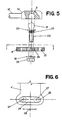
- the new pin 20, plus the sphere 21 and the threaded portion 22 which are in the prior pin 8 has a knurled or dented portion 23, the teeth of which will fit in the corresponding knurl or dented portion 24 of the inner surface of the oblong hole 25, located at the end of the new receiving element 4'.
- the knurled or dented circular portion 23 of the new pin 20 may fit any point of the knurled or dented portion 24 of the oblong hole 25.
- Fig. 6 there are, shown in dotted lines, the extreme positions 27 in which the pin 20 may be positioned and the distance between the two outside points 27 represents the useful length 28 of the knurled portion 24.
- the correct point of fit of pin 20 in the hole 25 will depend on the differences which are in each assembly, between the length of the transmission cable 3' and the corresponding distance for the assembly of the devices in which there are assembled, respectively, the transmitting element 2 and the receiving element 4' of the control.
- the useful length 28 of the knurled or dented portion 24 is dimensioned in order to be longer than most differences in length actually found.
- the first parts to be mounted are the devices which include, respectively, the transmitting 2 and the receiving element 4' with the transmission cable 3' already installed on the transmitting element 2, and the elements are then placed in the respective neutral positions.
- the inner cable 12' will be naturally fitted in such a way that its terminal 30 is close to the end of the receiving arm 4'.
- the pin 20, already fitted into the terminal 30, will remain also close to the oblong hole 25, in a position and in a distance which corresponds to the neutral position of the receiving element 4', which allows the right fitting of the dents 23 and 24 already in the right adjusted position.
- Fig. 5 shows how the end of the internal cable 12' is fixed directly to the terminal 30.
- the spherical seat 31, which fits the terminal 30, receives the spherical head 21 of the new dented pin 30.
Landscapes
- Engineering & Computer Science (AREA)
- General Engineering & Computer Science (AREA)
- Health & Medical Sciences (AREA)
- Oral & Maxillofacial Surgery (AREA)
- Mechanical Engineering (AREA)
- Flexible Shafts (AREA)
Priority Applications (4)
| Application Number | Priority Date | Filing Date | Title |
|---|---|---|---|
| US09/359,177 US6301992B1 (en) | 1999-07-22 | 1999-07-22 | Adjustment and assembly system for mechanical cable remote control |
| AU42336/99A AU774138B2 (en) | 1999-07-22 | 1999-07-28 | Adjustment and assembly system for mechanical cable remote control |
| EP99116809A EP1081397A1 (fr) | 1999-07-22 | 1999-09-01 | Dispositif de réglage et d'assemblage de commandes à distance par câble |
| EP99202964A EP1083344A1 (fr) | 1999-07-22 | 1999-09-10 | Système de réglage et montage pour le contrôle à distance par cable mécanique |
Applications Claiming Priority (4)
| Application Number | Priority Date | Filing Date | Title |
|---|---|---|---|
| US09/359,177 US6301992B1 (en) | 1999-07-22 | 1999-07-22 | Adjustment and assembly system for mechanical cable remote control |
| AU42336/99A AU774138B2 (en) | 1999-07-22 | 1999-07-28 | Adjustment and assembly system for mechanical cable remote control |
| EP99116809A EP1081397A1 (fr) | 1999-07-22 | 1999-09-01 | Dispositif de réglage et d'assemblage de commandes à distance par câble |
| EP99202964A EP1083344A1 (fr) | 1999-07-22 | 1999-09-10 | Système de réglage et montage pour le contrôle à distance par cable mécanique |
Publications (1)
| Publication Number | Publication Date |
|---|---|
| EP1083344A1 true EP1083344A1 (fr) | 2001-03-14 |
Family
ID=27506892
Family Applications (2)
| Application Number | Title | Priority Date | Filing Date |
|---|---|---|---|
| EP99116809A Withdrawn EP1081397A1 (fr) | 1999-07-22 | 1999-09-01 | Dispositif de réglage et d'assemblage de commandes à distance par câble |
| EP99202964A Withdrawn EP1083344A1 (fr) | 1999-07-22 | 1999-09-10 | Système de réglage et montage pour le contrôle à distance par cable mécanique |
Family Applications Before (1)
| Application Number | Title | Priority Date | Filing Date |
|---|---|---|---|
| EP99116809A Withdrawn EP1081397A1 (fr) | 1999-07-22 | 1999-09-01 | Dispositif de réglage et d'assemblage de commandes à distance par câble |
Country Status (3)
| Country | Link |
|---|---|
| US (1) | US6301992B1 (fr) |
| EP (2) | EP1081397A1 (fr) |
| AU (1) | AU774138B2 (fr) |
Cited By (2)
| Publication number | Priority date | Publication date | Assignee | Title |
|---|---|---|---|---|
| WO2012052494A1 (fr) * | 2010-10-22 | 2012-04-26 | Valeo Securite Habitacle | Procede de reglage d'un cable de commande d'un mecanisme de serrure de vehicule |
| CN110466487A (zh) * | 2019-09-12 | 2019-11-19 | 江西大乘汽车有限公司 | 一种驻车制动拉线组件结构 |
Families Citing this family (4)
| Publication number | Priority date | Publication date | Assignee | Title |
|---|---|---|---|---|
| US6520043B1 (en) * | 2000-06-30 | 2003-02-18 | Dura Global Technologies, Inc. | Transmission shifter with integrated cable adjustment mechanism |
| JP4124247B2 (ja) * | 2006-07-05 | 2008-07-23 | ヤマハ株式会社 | 楽曲練習支援装置、制御方法及びプログラム |
| JP4493678B2 (ja) * | 2007-03-27 | 2010-06-30 | 株式会社コナミデジタルエンタテインメント | ゲーム装置、ゲーム処理方法、ならびに、プログラム |
| US10190334B2 (en) | 2015-11-03 | 2019-01-29 | Schlage Lock Company Llc | Adjustable length cable |
Citations (5)
| Publication number | Priority date | Publication date | Assignee | Title |
|---|---|---|---|---|
| US4590819A (en) * | 1982-06-28 | 1986-05-27 | Teleflex Incorporated | Motion transmitting remote control assembly molded terminal connector |
| DE4135309A1 (de) * | 1991-10-25 | 1993-04-29 | Bayerische Motoren Werke Ag | Befestigungseinrichtung fuer ein betaetigungselement |
| DE29509798U1 (de) * | 1995-06-16 | 1995-10-26 | ZF Lemförder Metallwaren AG, 49448 Lemförde | Vorrichtung zur Einstellung der Seillänge eines Seilzuges |
| US5605074A (en) * | 1995-09-05 | 1997-02-25 | Teleflex Incorporated | Security collar for adjustable core element terminal |
| EP0859158A1 (fr) * | 1997-02-17 | 1998-08-19 | Adwest Bowden France S.A. | Dispositif pour raccorder un embout d'un câble de commande à distance à une rotule, et son application à la commande d'un boíte de vitesses |
Family Cites Families (4)
| Publication number | Priority date | Publication date | Assignee | Title |
|---|---|---|---|---|
| US4884467A (en) * | 1988-12-05 | 1989-12-05 | Babcock Industries Inc. | Cable control with seal |
| US5222413A (en) * | 1992-05-04 | 1993-06-29 | Ford Motor Company | Cable assembly having spring biasing adjustment |
| US5511442A (en) * | 1994-09-02 | 1996-04-30 | Atoma International, Inc. | Control system with bowden wire assembly end clip |
| US5709132A (en) * | 1996-07-22 | 1998-01-20 | Telefex Incorporated | Cable length adjustment mechanism |
-
1999
- 1999-07-22 US US09/359,177 patent/US6301992B1/en not_active Expired - Fee Related
- 1999-07-28 AU AU42336/99A patent/AU774138B2/en not_active Ceased
- 1999-09-01 EP EP99116809A patent/EP1081397A1/fr not_active Withdrawn
- 1999-09-10 EP EP99202964A patent/EP1083344A1/fr not_active Withdrawn
Patent Citations (5)
| Publication number | Priority date | Publication date | Assignee | Title |
|---|---|---|---|---|
| US4590819A (en) * | 1982-06-28 | 1986-05-27 | Teleflex Incorporated | Motion transmitting remote control assembly molded terminal connector |
| DE4135309A1 (de) * | 1991-10-25 | 1993-04-29 | Bayerische Motoren Werke Ag | Befestigungseinrichtung fuer ein betaetigungselement |
| DE29509798U1 (de) * | 1995-06-16 | 1995-10-26 | ZF Lemförder Metallwaren AG, 49448 Lemförde | Vorrichtung zur Einstellung der Seillänge eines Seilzuges |
| US5605074A (en) * | 1995-09-05 | 1997-02-25 | Teleflex Incorporated | Security collar for adjustable core element terminal |
| EP0859158A1 (fr) * | 1997-02-17 | 1998-08-19 | Adwest Bowden France S.A. | Dispositif pour raccorder un embout d'un câble de commande à distance à une rotule, et son application à la commande d'un boíte de vitesses |
Cited By (4)
| Publication number | Priority date | Publication date | Assignee | Title |
|---|---|---|---|---|
| WO2012052494A1 (fr) * | 2010-10-22 | 2012-04-26 | Valeo Securite Habitacle | Procede de reglage d'un cable de commande d'un mecanisme de serrure de vehicule |
| FR2966417A1 (fr) * | 2010-10-22 | 2012-04-27 | Valeo Securite Habitacle | Procede de reglage d'un cable de commande d'un mecanisme de serrure |
| CN110466487A (zh) * | 2019-09-12 | 2019-11-19 | 江西大乘汽车有限公司 | 一种驻车制动拉线组件结构 |
| CN110466487B (zh) * | 2019-09-12 | 2024-05-28 | 江西大乘汽车有限公司 | 一种驻车制动拉线组件结构 |
Also Published As
| Publication number | Publication date |
|---|---|
| US6301992B1 (en) | 2001-10-16 |
| AU774138B2 (en) | 2004-06-17 |
| AU4233699A (en) | 2001-02-08 |
| EP1081397A1 (fr) | 2001-03-07 |
Similar Documents
| Publication | Publication Date | Title |
|---|---|---|
| US6902341B1 (en) | Turnbuckle linkage assembly | |
| US4949585A (en) | Telescopic screw jack for the adjustment of an element such as a vehicle seat | |
| US4034574A (en) | Universal ball and socket swivel joint | |
| JPH03540B2 (fr) | ||
| US6038942A (en) | Manually adjusted device for control cable terminals | |
| AU774138B2 (en) | Adjustment and assembly system for mechanical cable remote control | |
| US5027673A (en) | Self-adjusting gear shift lever assembly | |
| US7340981B1 (en) | Angled and offset drive ratchet extension | |
| KR20110027663A (ko) | 연결 시스템 | |
| US5735177A (en) | Remote control mechanisms | |
| US5182962A (en) | Actuating force transmission unit for a gear change mechanism of a bicycle | |
| CN1178009C (zh) | 机械钢绳遥控用的调整与组装系统 | |
| JP2001117658A (ja) | 機械ケーブル遠隔制御装置の調整及び組立システム | |
| US5984232A (en) | Flexible shaft driven rotary control valve | |
| JPH02128994A (ja) | 船用推進装置のトランスミッション装置用の連結装置 | |
| JP2709352B2 (ja) | 弁軸とアクチュエータ駆動軸の結合方法 | |
| PL195933B1 (pl) | Urządzenie do mocowania i regulowania linki przekazującej | |
| KR20000057341A (ko) | 제어 하프-케이블 연결 디바이스 | |
| KR100452196B1 (ko) | 차량용 악셀 케이블 연결구조 | |
| JP2502709B2 (ja) | 自動変速機のスロットルケ―ブル配線方法及びスロットルカム固定構造 | |
| KR100909956B1 (ko) | 케이블을 중립위치에 조정하는 장치 | |
| KR20010019412A (ko) | 기계적 케이블에 의한 원격제어용 조정 및 조립시스템 | |
| JPH11351269A (ja) | 球面軸受けの角度規制構造 | |
| PL116153B1 (en) | Screw gear for tensionong drive transmission members offlexible connector transmissions | |
| KR200160718Y1 (ko) | 변속기 조작케이블의 연결구조 |
Legal Events
| Date | Code | Title | Description |
|---|---|---|---|
| PUAI | Public reference made under article 153(3) epc to a published international application that has entered the european phase |
Free format text: ORIGINAL CODE: 0009012 |
|
| AK | Designated contracting states |
Kind code of ref document: A1 Designated state(s): AT BE CH CY DE DK ES FI FR GB GR IE IT LI LU MC NL PT SE |
|
| AX | Request for extension of the european patent |
Free format text: AL;LT;LV;MK;RO;SI |
|
| AKX | Designation fees paid | ||
| STAA | Information on the status of an ep patent application or granted ep patent |
Free format text: STATUS: THE APPLICATION IS DEEMED TO BE WITHDRAWN |
|
| 18D | Application deemed to be withdrawn |
Effective date: 20010915 |
|
| REG | Reference to a national code |
Ref country code: DE Ref legal event code: 8566 |