EP1083636A2 - Vorrichtung zum Verhindern des Entkuppelns eines elektrischen Verbinders - Google Patents
Vorrichtung zum Verhindern des Entkuppelns eines elektrischen Verbinders Download PDFInfo
- Publication number
- EP1083636A2 EP1083636A2 EP00402454A EP00402454A EP1083636A2 EP 1083636 A2 EP1083636 A2 EP 1083636A2 EP 00402454 A EP00402454 A EP 00402454A EP 00402454 A EP00402454 A EP 00402454A EP 1083636 A2 EP1083636 A2 EP 1083636A2
- Authority
- EP
- European Patent Office
- Prior art keywords
- ring
- coupling nut
- spring ring
- connector shell
- decoupling
- Prior art date
- Legal status (The legal status is an assumption and is not a legal conclusion. Google has not performed a legal analysis and makes no representation as to the accuracy of the status listed.)
- Withdrawn
Links
Images


Classifications
-
- H—ELECTRICITY
- H01—ELECTRIC ELEMENTS
- H01R—ELECTRICALLY-CONDUCTIVE CONNECTIONS; STRUCTURAL ASSOCIATIONS OF A PLURALITY OF MUTUALLY-INSULATED ELECTRICAL CONNECTING ELEMENTS; COUPLING DEVICES; CURRENT COLLECTORS
- H01R13/00—Details of coupling devices of the kinds covered by groups H01R12/70 or H01R24/00 - H01R33/00
- H01R13/62—Means for facilitating engagement or disengagement of coupling parts or for holding them in engagement
- H01R13/622—Screw-ring or screw-casing
Definitions
- the present invention generally relates to anti-decoupling arrangements for connectors of the type in which coupling is achieved by means of a coupling nut, and more particularly to an anti-decoupling arrangement for an electrical connector that uses a ratchet mechanism to limit rotation of the coupling nut in the decoupling direction and a spiral lock clutch to permit free rotation of the coupling nut in the coupling direction. Still more particularly, the invention relates to improvements on the anti-decoupling arrangement disclosed in commonly assigned U.S. Patent No.4,536,048.
- a typical connector to which the present invention may be applied includes a connector shell containing electrical contacts and an internally threaded coupling nut rotatably mounted on the connector shell.
- the connector shell is coupled to a corresponding externally threaded mating connector by means ofthe coupling nut in such a manner that electrical contacts in the mating connector engage the electrical contacts in the connector shell.
- the coupling nut is held on the connector shell by one or more snap rings and/or spring washers that are designed to captivate or press a radial flange of the coupling nut against a corresponding flange or shoulder on the connector shell.
- the simplest and most common method of preventing unintended decoupling as a result of shocks or vibrations has been to include in the connector a metal ratchet spring having protrusions or dimples at the center of the beam, the ratchet spring being permanently attached to the inside diameter of the threaded coupling nut.
- the connector shell is provided with ratchet teeth on its outer diameter, which are engaged by the ratchet spring.
- the spiral lock clutch is arranged to unwind in response to turning of the nut in a coupling direction, thereby permitting the clutch to move freely in response to tightening of the nut so as to minimize the locking torque and consequently wear on the anti-decoupling mechanism.
- application of a torque to the ratchet in the opposite or uncoupling direction causes the clutch to engage the shell and lock the spring tine 2 relative to the plug connector shell 6, preventing rotation and therefore accidental loosening.
- the spring tine is able to ratchet over the teeth, thereby permitting rotation of the coupling nut in the decoupling direction.
- the present invention offers various improvements to the decoupling mechanism described in U.S. Patent No. 4,536,048, including a higher and more easily adjusted decoupling torque, and greater reliability than can be provided by the single detent inherent in the use of the lateral detent and spring lock clutch design disclosed in U.S. Patent No. 4,536,048.
- an anti-decoupling arrangement for an electrical connector (as well as an electrical connector incorporating such an anti-decoupling arrangement) which includes, in addition to a spiral lock clutch, a spring ring, and a separate ratchet wheel or tooth ring having a plurality of radial cuts, all surrounding the connector shell and sandwiched between a flange or shoulder on the connector shell by a conventional snap ring.
- the tooth ring is advantageously situated in the space between the thread of the coupling nut and the flange or shoulder that forms the inner surface of a recessed area with the coupling nut, while the shell preferably includes at least one groove for the snap ring and, in the illustrated embodiment, an optional second groove for the spiral lock clutch.
- the groove for the snap ring and the optional groove for the spiral lock clutch are situated behind the flange or shoulder towards the rear of the connector, the shell providing axial alignment of all components except the spring ring.
- the tooth ring may include extensions that cooperate with a notch or slot in the coupling nut, a plurality of knurls or protrusions on the outside diameter of the tooth ring which engage and deform into an internal diameter of the coupling nut, or other means for locking the tooth ring against angular rotation relative to the coupling nut, while the spring ring preferably include an extension in engagement with a notch in the spiral lock clutch so that the spring ring is locked against angular rotation relative to a spring ring.
- the spring ring member is a self supporting ring that has spring tines of a given number located angularly around its radial wall. These tines provide the ratchet mechanism when they glide over the radial cuts of the tooth ring in the uncoupling direction. This provides a free running clutch in the coupling direction and a torque/ratchet mechanism in the uncoupling direction.
- the teeth on the tooth ring engage the spring tines and cause the spring ring to also turn in the coupling direction, which causes the spiral lock clutch to turn in the coupling direction.
- Turning of the spiral lock clutch in the coupling direction causes it to unwind from the connector shell and freely rotate, thus permitting coupling to occur without any resistance from the anti-decoupling mechanism.
- the provision of the teeth on a separate tooth ring is preferred for reasons of manufacturability, it may be possible in a variation of the preferred embodiment to essentially flip the preferred anti-decoupling mechanism by 180 degrees, reversing the order of the elements and in particular forming the teeth so that they extend axially from the inwardly extending flange in the coupling nut.
- Fig. 1 is an isometric view showing a prior art anti-decoupling arrangement.
- Fig. 2 is an isometric view showing an electrical connector anti-decoupling arrangement constructed in accordance with the principles of a preferred embodiment of the invention.
- Fig. 3 is a cross-sectional side view of the electrical connector and anti-decoupling arrangement of Fig. 2.
- Fig. 4 is an isometric view showing details of a tooth ring for use in the anti-decoupling arrangement of the preferred embodiment.
- Fig. 5 is an enlarged isometric view of a portion of the tooth ring illustrated in Fig. 4.
- Fig. 6 is an isometric view showing a spring ring for use in the anti-decoupling arrangement of the preferred embodiment.
- Fig. 7 is an isometric view showing a rear and side ofa coupling nut for use in the anti-decoupling arrangement of the preferred embodiment.
- Fig. 8 is an isometric view showing details of the engagement between the spring ring and spiral lock clutch of the preferred embodiment.
- Fig. 9 is an isometric view of a variation of the spring ring/clutch engaging arrangement illustrated in Fig. 8.
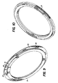
- Fig. 10 is an isometric view of a variation of the tooth ring of the preferred embodiment.
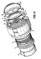
- Fig. 11 is an isometric view of a connector utilizing the variation of the tooth ring illustrated in Fig. 10.
- Fig. 12 is an isometric view of a variation of the anti-decoupling arrangements of Figs. 1-11, in which the tooth ring is integrated with the coupling nut.
- a connector having a anti-decoupling mechanism constructed in accordance with the principles of a preferred embodiment of the invention includes a plug connector shell 8 having a front mating section corresponding to the one illustrated in U.S. Patent No. 4,536,048, incorporated herein by reference. Between the front and rear section of the plug connector shell 8 is a flange or shoulder 9 having a rear surface 10 which faces a collar or flange 11 extending radially inwardly from the coupling nut 12.
- the illustrated connector shell 8 and coupling nut 12 have the general configuration of a type of connector known as the "Series III" connector, including such features as polarizing keys 13, and a standard Tri-start thread 14 on the coupling nut 12.
- Series III a type of connector known as the "Series III" connector
- the anti-decoupling arrangement of the preferred embodiment is especially suitable for use in the Series III connector, which is designed to be used in harsh environments (the standards therefor being specified in standard shell sizes 9-25 according to MIL-C-38999/26D, dated May 7, 1990), those skilled in the art will appreciate that the principles of the invention are not limited to Series III connectors, but rather are applicable to any cylindrical connectors having threaded couplings and a need for an anti-decoupling arrangement.
- Spiral lock clutch 19 is preferably in the form of a wound radial spring band surrounding the shell 13 or, optionally, interference fit into a groove (not shown) in the shell, and includes a notch 20 at a rearward side near an end 21 of the clutch.
- Notch 20 is arranged to receive a rearwardly extending protrusion 22 of a spring ring 23 such that when the spring ring 23 is fitted onto the plug connector shell and oriented so that protrusion 22 aligns with notch 20, spring ring 23 and end 21 are thereby locked against relative movement.
- spiral lock clutch 19 may be similar to the spiral ring disclosed in U.S. Patent No. 4,536,048.
- protrusion 22 Details of the protrusion 22 are illustrated in Figs. 6 and 8. Although illustrated as a tab bent backwards over the spring ring 23, those skilled in the art will appreciate that protrusion 22 may take a variety of forms so long as it is capable of cooperating with corresponding structures on clutch 19 to lock clutch 19 against rotation relative to spring ring 23. In addition, it will be appreciated by those skilled in the art that, instead of a protrusion 22 and notch 20 at the rearward side of the spiral lock clutch 19 and protrusion 22 on spring ring 23, the spiral lock clutch 19 and protrusion 22 may be locked together against rotation by a weld joint 40, as illustrated in Fig. 9, or by any other suitable joining structure.
- Spring ring 23 includes, in addition to rearwardly facing protrusion 22, a plurality of forwardly extending spring tines or beams 24, as shown in Fig. 4.
- Spring beams 24 preferably include angled sections 25 arranged to cooperate with corresponding teeth 26 on tooth ring 27 to provide a ratcheting effect, as described below, when tooth ring 27 is fitted over the plug connector shell, with the toothed front surface of the tooth ring facing the rear surface of the spring ring.
- Tooth ring 27 includes at least one tab or projection 28 engageable with a slot or notch 29 at the rear of the coupling nut to lock tooth ring 27 against rotation relative to the coupling nut 16, so that the toothed ring turns with the coupling nut.
- a flange 30 extends from the tooth ring and engages the rear surface 31 of the coupling nut to retain the coupling nut upon securing the tooth ring 27 in place using snap ring 32, which is retained by a groove 18 in the rear section of the plug connector shell.
- Teeth 26 are formed by radial cuts and preferably have angled edges that permit ratcheting with an appropriate torque during decoupling. The angle of the sides against which the beams 24 are pressed during decoupling is not critical due to the nominal torque resulting from release of the clutch during coupling.
- the manner in which the tooth ring is locked against rotation relatively to the coupling nut is not limited to the protrusion and notch illustrated in Figs. 1 and 2.
- the tooth ring may be modified to form a tooth ring 27' that includes a plurality of knurls or protrusions 41 on the outside diameter of the tooth ring which engage and deform, i.e. , are press-fit, into an internal diameter 42 of the coupling nut 12, in which case the flange 30 would be omitted from the tooth ring.
- the anti-decoupling mechanism of the preferred embodiments illustrated in Figs. 1-11 is assembled to the connector, as follows:
- the connector thus assembled operates as follows: When the coupling nut 12 is rotated in the mating or coupling direction, tooth ring 27 also rotates in the coupling direction, causing teeth 26 to exert a torque on cantilever beams 24, rotating the spring ring 23, which in turn rotates the spiral lock clutch 19 in a direction which causes the clutch to unwind from the plug connector shell 8 and freely rotate relative thereto. As a result, the coupling nut can be rotated with a light torque to secure the coupling nut 12 to a mating connector.
- the illustrated connector and decoupling arrangement may be further varied or modified by those skilled in the art.
- the type of connector to which the decoupling arrangement of the preferred embodiment is applied may be freely modified, as may such details as the nature of the complementary interengaging surfaces between the coupling nut and the plug connector shell ( i.e., flanges 9 and 11) or the structures that lock the spring ring 23/spiral lock clutch 19 and tooth ring 27/coupling nut 12 against mutual angular movement.
Landscapes
- Details Of Connecting Devices For Male And Female Coupling (AREA)
Applications Claiming Priority (2)
| Application Number | Priority Date | Filing Date | Title |
|---|---|---|---|
| US09/391,458 US6123563A (en) | 1999-09-08 | 1999-09-08 | Anti-decoupling arrangement for an electrical connector |
| US391458 | 1999-09-08 |
Publications (2)
| Publication Number | Publication Date |
|---|---|
| EP1083636A2 true EP1083636A2 (de) | 2001-03-14 |
| EP1083636A3 EP1083636A3 (de) | 2004-12-22 |
Family
ID=23546683
Family Applications (1)
| Application Number | Title | Priority Date | Filing Date |
|---|---|---|---|
| EP00402454A Withdrawn EP1083636A3 (de) | 1999-09-08 | 2000-09-06 | Vorrichtung zum Verhindern des Entkuppelns eines elektrischen Verbinders |
Country Status (4)
| Country | Link |
|---|---|
| US (1) | US6123563A (de) |
| EP (1) | EP1083636A3 (de) |
| JP (1) | JP3559759B2 (de) |
| CA (1) | CA2317823A1 (de) |
Cited By (2)
| Publication number | Priority date | Publication date | Assignee | Title |
|---|---|---|---|---|
| DE102005052764A1 (de) * | 2005-11-04 | 2007-05-16 | Tyco Electronics Amp Gmbh | Verbindungsanordnung mit einem Verriegelungsmechanismus sowie Sicherungselement für eine derartige Verbindungsanordnung |
| CN115332847A (zh) * | 2021-05-10 | 2022-11-11 | 泰连德国有限公司 | 带支撑环的电接触元件 |
Families Citing this family (40)
| Publication number | Priority date | Publication date | Assignee | Title |
|---|---|---|---|---|
| GB9928070D0 (en) * | 1999-11-29 | 2000-01-26 | Beldray Ltd | A handwheel for a nursery gate adjustment mechanism |
| GB9928256D0 (en) * | 1999-11-30 | 2000-01-26 | Smiths Industries Plc | Electrical couplings,connectors and components |
| DE202004014020U1 (de) * | 2004-09-09 | 2006-02-09 | Krauss-Maffei Wegmann Gmbh & Co. Kg | Steckverbinder zur Leitungsdurchführung durch eine Öffnung einer Trennwand eines insbesondere militärischen Gerätes |
| US6966788B1 (en) | 2005-03-15 | 2005-11-22 | Ruhl Jr Harold John | Anti-decoupling mechanism for solid or tubular circular cross section assemblies having a rotating coupling nut or nuts |
| US7431602B2 (en) * | 2005-04-21 | 2008-10-07 | Dsm & T Co., Inc. | Electrical connector |
| KR100601135B1 (ko) | 2005-12-29 | 2006-07-19 | 성 운 한 | 전기 접속용 커넥터의 플러그 구조 |
| JP4756204B2 (ja) * | 2007-08-31 | 2011-08-24 | 丸一株式会社 | 配管用ナット |
| US9106012B2 (en) * | 2008-05-30 | 2015-08-11 | Itt Manufacturing Enterprises, Inc. | Antirotation coupling for connector |
| US7845963B2 (en) * | 2008-10-21 | 2010-12-07 | Itt Manufacturing Enterprises, Inc. | Axial anti-rotation coupling |
| US7625226B1 (en) * | 2008-12-02 | 2009-12-01 | Itt Manufacturing Enterprises, Inc. | Radial anti-rotation coupling |
| US8070504B2 (en) * | 2009-06-17 | 2011-12-06 | John Mezzalingua Associates, Inc. | Coaxial cable port locking terminator and method of use thereof |
| US7914311B1 (en) * | 2009-11-06 | 2011-03-29 | Amphenol Corporation | Anti-vibration connector coupling with an axially movable ratchet ring and a collar |
| US7905741B1 (en) * | 2009-11-06 | 2011-03-15 | Amphenol Corporation | Anti-vibration connector coupling with an axially movable ratchet ring |
| FR2956255B1 (fr) * | 2010-02-05 | 2014-08-08 | Souriau | Dispositif anti-deverrouillage pour connecteur |
| CN101807765B (zh) * | 2010-03-24 | 2012-08-22 | 中航光电科技股份有限公司 | 电连接器 |
| CN101814672B (zh) * | 2010-03-24 | 2011-12-21 | 中航光电科技股份有限公司 | 抗震连接器 |
| IL213239A (en) * | 2010-06-08 | 2017-02-28 | Amphenol Corp | Connection to the connector |
| CN101908691B (zh) * | 2010-06-21 | 2012-12-19 | 贵州航天电器股份有限公司 | 一种连接器锁紧及电磁解锁装置 |
| US8579644B2 (en) | 2012-03-13 | 2013-11-12 | Amphenol Corporation | Anti-vibration connector coupling with disengagement feature |
| KR101378446B1 (ko) | 2012-12-28 | 2014-03-26 | 우진 일렉트로나이트(주) | 연장케이블 |
| IL231455A0 (en) | 2013-03-15 | 2014-08-31 | Amphenol Corp | Connection to a locking connector |
| US9397441B2 (en) * | 2013-03-15 | 2016-07-19 | Cinch Connections, Inc. | Connector with anti-decoupling mechanism |
| KR101401943B1 (ko) * | 2013-03-18 | 2014-06-02 | 주식회사 우진 | 전기 접속용 커넥터의 리셉터클 |
| US9099807B2 (en) * | 2013-12-05 | 2015-08-04 | Itt Manufacturing Enterprises, Llc | Releasable locking connector assembly |
| US9528646B2 (en) | 2014-05-02 | 2016-12-27 | Itt Manufacturing Enterprises, Llc | Locking and ratcheting connector |
| US9559457B2 (en) | 2014-07-16 | 2017-01-31 | Amphenol Corporation | Anti-vibration coupling device |
| US9362666B2 (en) * | 2014-09-12 | 2016-06-07 | Cooper Technologies Company | Anti-decoupling spring |
| US9666973B1 (en) * | 2016-06-10 | 2017-05-30 | Amphenol Corporation | Self-locking connector coupling |
| US10756482B2 (en) | 2016-09-20 | 2020-08-25 | Itt Manufacturing Enterprises Llc | Torque-limiting couplings |
| CN109038103B (zh) * | 2016-10-20 | 2020-04-24 | 浙江美固科技有限公司 | 一种充电连接系统 |
| CN108214570B (zh) * | 2017-10-23 | 2020-10-27 | 浙江立昌健康产品科技有限公司 | 一种实用的电剃须刀 |
| US10790615B2 (en) * | 2018-12-28 | 2020-09-29 | Raytheon Company | Cable quick connector adapter |
| CN111555080B (zh) * | 2019-02-11 | 2021-09-07 | 正凌精密工业(广东)有限公司 | 抗振动连接器及其组装方法 |
| CN110943325A (zh) * | 2019-12-09 | 2020-03-31 | 胡锋 | 一种电子信号传输线缆连接用插接头 |
| DE102020102575A1 (de) | 2020-02-03 | 2021-08-05 | Harting Electric Gmbh & Co. Kg | Rundsteckverbinder mit Schirmübertragung |
| CN111541075B (zh) * | 2020-05-20 | 2022-05-20 | 中航光电科技股份有限公司 | 一种防止波纹弹簧磨损的连接器 |
| DE102020120306A1 (de) * | 2020-07-31 | 2022-02-03 | Harting Electric Gmbh & Co. Kg | Rundsteckverbinder mit Schirmanbindung |
| TW202207547A (zh) | 2020-08-13 | 2022-02-16 | 美商安芬諾股份有限公司 | 連接器耦接件 |
| DE102021101684B3 (de) | 2021-01-26 | 2022-03-17 | Ifm Electronic Gmbh | Verfahren zur Herstellung eines Steckverbinders und verfahrensgemäß hergestellter Steckverbinder |
| CN217427232U (zh) * | 2022-04-11 | 2022-09-13 | 东莞富强电子有限公司 | 充电连接器 |
Family Cites Families (22)
| Publication number | Priority date | Publication date | Assignee | Title |
|---|---|---|---|---|
| US4030798A (en) * | 1975-04-11 | 1977-06-21 | Akzona Incorporated | Electrical connector with means for maintaining a connected condition |
| US4109990A (en) * | 1977-05-26 | 1978-08-29 | The Bendix Corporation | Electrical connector assembly having anti-decoupling mechanism |
| US4479689A (en) * | 1982-09-30 | 1984-10-30 | The Bendix Corporation | Coupling nut for an electrical connector |
| US4484790A (en) * | 1983-03-30 | 1984-11-27 | The Bendix Corporation | Anti-decoupling device for an electrical connector |
| US4487470A (en) * | 1983-05-11 | 1984-12-11 | The Bendix Corporation | Anti-decoupling mechanism for an electrical connector assembly |
| US4588246A (en) * | 1983-05-11 | 1986-05-13 | Allied Corporation | Anti-decoupling mechanism for an electrical connector assembly |
| US4536048A (en) * | 1983-05-11 | 1985-08-20 | Allied Corporation | Anti-decoupling mechanism for an electrical connector assembly |
| US4508408A (en) * | 1983-05-11 | 1985-04-02 | Allied Corporation | Anti-decoupling mechanism for an electrical connector assembly |
| US4519661A (en) * | 1983-12-09 | 1985-05-28 | Allied Corporation | Connector assembly having an anti-decoupling mechanism |
| US4641811A (en) * | 1984-08-02 | 1987-02-10 | Allied Corp. | Electrical connector having a molded anti-decoupling mechanism |
| FR2587552B1 (fr) * | 1985-09-13 | 1987-12-18 | Socapex | Connecteur electrique comportant un dispositif anti-deverrouillage |
| US4808123A (en) * | 1987-02-04 | 1989-02-28 | Diverse Termination Products, Inc. | Self-locking strain-relief end bell for electrical connector assembly |
| US4726782A (en) * | 1987-01-05 | 1988-02-23 | G & H Technology, Inc. | Anti-decoupling device for an electrical connector |
| US5082454A (en) * | 1989-09-28 | 1992-01-21 | Joslyn Corporation | Two-piece retaining ring |
| US4984995A (en) * | 1989-11-13 | 1991-01-15 | Icore International, Inc. | Anti-decoupling device for electrical conduit connector |
| US5199894A (en) * | 1990-12-14 | 1993-04-06 | Kalny Lou E | Self-locking connector |
| US5145394A (en) * | 1991-10-03 | 1992-09-08 | G & H Technology, Inc. | Anti-rotation assembly for interconnect devices |
| US5681177A (en) * | 1995-01-25 | 1997-10-28 | Amphenol Corporation | Anti-decoupling device |
| GB2299460B (en) * | 1995-03-31 | 1998-12-30 | Ultra Electronics Ltd | Locking coupling |
| US5653605A (en) * | 1995-10-16 | 1997-08-05 | Woehl; Roger | Locking coupling |
| US5702263A (en) * | 1996-03-12 | 1997-12-30 | Hirel Connectors Inc. | Self locking connector backshell |
| US5785545A (en) * | 1996-07-02 | 1998-07-28 | The Deutsch Company | Connector for joining two electrical connection assemblies |
-
1999
- 1999-09-08 US US09/391,458 patent/US6123563A/en not_active Expired - Fee Related
-
2000
- 2000-09-05 JP JP2000268994A patent/JP3559759B2/ja not_active Expired - Fee Related
- 2000-09-06 EP EP00402454A patent/EP1083636A3/de not_active Withdrawn
- 2000-09-07 CA CA002317823A patent/CA2317823A1/en not_active Abandoned
Cited By (3)
| Publication number | Priority date | Publication date | Assignee | Title |
|---|---|---|---|---|
| DE102005052764A1 (de) * | 2005-11-04 | 2007-05-16 | Tyco Electronics Amp Gmbh | Verbindungsanordnung mit einem Verriegelungsmechanismus sowie Sicherungselement für eine derartige Verbindungsanordnung |
| DE102005052764B4 (de) * | 2005-11-04 | 2007-12-06 | Tyco Electronics Amp Gmbh | Verbindungsanordnung mit einem Verriegelungsmechanismus sowie Sicherungselement für eine derartige Verbindungsanordnung |
| CN115332847A (zh) * | 2021-05-10 | 2022-11-11 | 泰连德国有限公司 | 带支撑环的电接触元件 |
Also Published As
| Publication number | Publication date |
|---|---|
| JP3559759B2 (ja) | 2004-09-02 |
| US6123563A (en) | 2000-09-26 |
| CA2317823A1 (en) | 2001-03-08 |
| JP2001110514A (ja) | 2001-04-20 |
| EP1083636A3 (de) | 2004-12-22 |
Similar Documents
| Publication | Publication Date | Title |
|---|---|---|
| US6123563A (en) | Anti-decoupling arrangement for an electrical connector | |
| US6152753A (en) | Anti-decoupling arrangement for an electrical connector | |
| US4109990A (en) | Electrical connector assembly having anti-decoupling mechanism | |
| US6358077B1 (en) | G-load coupling nut | |
| US11517731B2 (en) | Luer lock adaptor | |
| US6602085B2 (en) | G-load coupling nut | |
| US4588246A (en) | Anti-decoupling mechanism for an electrical connector assembly | |
| EP2325951B1 (de) | Vibrationsdämpfende Verbindungskupplung | |
| US4525017A (en) | Anti-decoupling mechanism for an electrical connector assembly | |
| US5399096A (en) | Electrical connector having a threaded ring and means for retaining it in locked condition | |
| US4648670A (en) | Electrical connector assembly having anti-decoupling mechanism | |
| CA2397518C (en) | Automatic latching lockout shaft sensing coupler | |
| US4487470A (en) | Anti-decoupling mechanism for an electrical connector assembly | |
| US4484790A (en) | Anti-decoupling device for an electrical connector | |
| KR950002113A (ko) | 변형이 감소된 케이블 커넥터 | |
| US4552427A (en) | Self-locking connector | |
| US4536048A (en) | Anti-decoupling mechanism for an electrical connector assembly | |
| US4508408A (en) | Anti-decoupling mechanism for an electrical connector assembly | |
| US4462652A (en) | Coupling nut for an electrical connector | |
| EP0708496A2 (de) | Elektrische Verbinderanordnung mit verbessertem Entkupplungsverzögerungsmechanismus | |
| JPS5917285B2 (ja) | ねじ連結用回転止ロツク装置 | |
| US4502748A (en) | Anti-decoupling device for an electrical connector | |
| US6234819B1 (en) | Mechanism for detecting an unlocked state of connectors | |
| US4506942A (en) | Anti-decoupling mechanism for electrical connector | |
| US4255008A (en) | Electrical connector assembly having anti-decoupling device |
Legal Events
| Date | Code | Title | Description |
|---|---|---|---|
| PUAI | Public reference made under article 153(3) epc to a published international application that has entered the european phase |
Free format text: ORIGINAL CODE: 0009012 |
|
| AK | Designated contracting states |
Kind code of ref document: A2 Designated state(s): AT BE CH CY DE DK ES FI FR GB GR IE IT LI LU MC NL PT SE |
|
| AX | Request for extension of the european patent |
Free format text: AL;LT;LV;MK;RO;SI |
|
| PUAL | Search report despatched |
Free format text: ORIGINAL CODE: 0009013 |
|
| AK | Designated contracting states |
Kind code of ref document: A3 Designated state(s): AT BE CH CY DE DK ES FI FR GB GR IE IT LI LU MC NL PT SE |
|
| AX | Request for extension of the european patent |
Extension state: AL LT LV MK RO SI |
|
| 17P | Request for examination filed |
Effective date: 20050608 |
|
| AKX | Designation fees paid |
Designated state(s): DE FR GB IT NL SE |
|
| 17Q | First examination report despatched |
Effective date: 20050919 |
|
| STAA | Information on the status of an ep patent application or granted ep patent |
Free format text: STATUS: THE APPLICATION IS DEEMED TO BE WITHDRAWN |
|
| 18D | Application deemed to be withdrawn |
Effective date: 20070626 |