EP1084757A2 - Pistolet de pulvérisation comprenant un dispositif de gestion de données et procédé de commande - Google Patents
Pistolet de pulvérisation comprenant un dispositif de gestion de données et procédé de commande Download PDFInfo
- Publication number
- EP1084757A2 EP1084757A2 EP00308065A EP00308065A EP1084757A2 EP 1084757 A2 EP1084757 A2 EP 1084757A2 EP 00308065 A EP00308065 A EP 00308065A EP 00308065 A EP00308065 A EP 00308065A EP 1084757 A2 EP1084757 A2 EP 1084757A2
- Authority
- EP
- European Patent Office
- Prior art keywords
- spray gun
- power supply
- information
- controller
- spray
- Prior art date
- Legal status (The legal status is an assumption and is not a legal conclusion. Google has not performed a legal analysis and makes no representation as to the accuracy of the status listed.)
- Withdrawn
Links
- 239000007921 spray Substances 0.000 title claims abstract description 247
- 238000000034 method Methods 0.000 title abstract description 16
- 238000000576 coating method Methods 0.000 claims description 16
- 239000011248 coating agent Substances 0.000 claims description 15
- 239000004020 conductor Substances 0.000 claims description 3
- 238000009503 electrostatic coating Methods 0.000 claims 1
- 239000000843 powder Substances 0.000 description 25
- 238000012360 testing method Methods 0.000 description 18
- 230000001276 controlling effect Effects 0.000 description 10
- 239000002245 particle Substances 0.000 description 10
- 238000004891 communication Methods 0.000 description 9
- 238000010586 diagram Methods 0.000 description 7
- 239000000463 material Substances 0.000 description 7
- 230000003139 buffering effect Effects 0.000 description 3
- 239000012530 fluid Substances 0.000 description 3
- 239000003973 paint Substances 0.000 description 3
- 238000003860 storage Methods 0.000 description 3
- 230000008901 benefit Effects 0.000 description 2
- 230000000694 effects Effects 0.000 description 2
- 230000005684 electric field Effects 0.000 description 2
- 230000005686 electrostatic field Effects 0.000 description 2
- 238000005243 fluidization Methods 0.000 description 2
- 230000006870 function Effects 0.000 description 2
- 238000012544 monitoring process Methods 0.000 description 2
- 229940098458 powder spray Drugs 0.000 description 2
- 230000008569 process Effects 0.000 description 2
- 230000001960 triggered effect Effects 0.000 description 2
- 101100521334 Mus musculus Prom1 gene Proteins 0.000 description 1
- 230000003047 cage effect Effects 0.000 description 1
- 238000010888 cage effect Methods 0.000 description 1
- 239000003990 capacitor Substances 0.000 description 1
- 229920005994 diacetyl cellulose Polymers 0.000 description 1
- 239000012777 electrically insulating material Substances 0.000 description 1
- 230000008030 elimination Effects 0.000 description 1
- 238000003379 elimination reaction Methods 0.000 description 1
- 230000000977 initiatory effect Effects 0.000 description 1
- 150000002500 ions Chemical class 0.000 description 1
- 239000007788 liquid Substances 0.000 description 1
- 238000012423 maintenance Methods 0.000 description 1
- 238000004519 manufacturing process Methods 0.000 description 1
- 230000013011 mating Effects 0.000 description 1
- 230000007246 mechanism Effects 0.000 description 1
- 239000002184 metal Substances 0.000 description 1
- 238000012986 modification Methods 0.000 description 1
- 230000004048 modification Effects 0.000 description 1
- 230000037361 pathway Effects 0.000 description 1
- 238000004382 potting Methods 0.000 description 1
- 238000010433 powder painting Methods 0.000 description 1
- 238000012545 processing Methods 0.000 description 1
- 230000001105 regulatory effect Effects 0.000 description 1
- 239000004065 semiconductor Substances 0.000 description 1
- 238000005507 spraying Methods 0.000 description 1
- 239000000037 vitreous enamel Substances 0.000 description 1
Images


Classifications
-
- B—PERFORMING OPERATIONS; TRANSPORTING
- B05—SPRAYING OR ATOMISING IN GENERAL; APPLYING FLUENT MATERIALS TO SURFACES, IN GENERAL
- B05B—SPRAYING APPARATUS; ATOMISING APPARATUS; NOZZLES
- B05B5/00—Electrostatic spraying apparatus; Spraying apparatus with means for charging the spray electrically; Apparatus for spraying liquids or other fluent materials by other electric means
- B05B5/025—Discharge apparatus, e.g. electrostatic spray guns
- B05B5/03—Discharge apparatus, e.g. electrostatic spray guns characterised by the use of gas, e.g. electrostatically assisted pneumatic spraying
- B05B5/032—Discharge apparatus, e.g. electrostatic spray guns characterised by the use of gas, e.g. electrostatically assisted pneumatic spraying for spraying particulate materials
-
- B—PERFORMING OPERATIONS; TRANSPORTING
- B05—SPRAYING OR ATOMISING IN GENERAL; APPLYING FLUENT MATERIALS TO SURFACES, IN GENERAL
- B05B—SPRAYING APPARATUS; ATOMISING APPARATUS; NOZZLES
- B05B12/00—Arrangements for controlling delivery; Arrangements for controlling the spray area
- B05B12/08—Arrangements for controlling delivery; Arrangements for controlling the spray area responsive to condition of liquid or other fluent material to be discharged, of ambient medium or of target ; responsive to condition of spray devices or of supply means, e.g. pipes, pumps or their drive means
-
- B—PERFORMING OPERATIONS; TRANSPORTING
- B05—SPRAYING OR ATOMISING IN GENERAL; APPLYING FLUENT MATERIALS TO SURFACES, IN GENERAL
- B05B—SPRAYING APPARATUS; ATOMISING APPARATUS; NOZZLES
- B05B5/00—Electrostatic spraying apparatus; Spraying apparatus with means for charging the spray electrically; Apparatus for spraying liquids or other fluent materials by other electric means
-
- G—PHYSICS
- G05—CONTROLLING; REGULATING
- G05B—CONTROL OR REGULATING SYSTEMS IN GENERAL; FUNCTIONAL ELEMENTS OF SUCH SYSTEMS; MONITORING OR TESTING ARRANGEMENTS FOR SUCH SYSTEMS OR ELEMENTS
- G05B2219/00—Program-control systems
- G05B2219/30—Nc systems
- G05B2219/45—Nc applications
- G05B2219/45013—Spraying, coating, painting
-
- G—PHYSICS
- G05—CONTROLLING; REGULATING
- G05B—CONTROL OR REGULATING SYSTEMS IN GENERAL; FUNCTIONAL ELEMENTS OF SUCH SYSTEMS; MONITORING OR TESTING ARRANGEMENTS FOR SUCH SYSTEMS OR ELEMENTS
- G05B2219/00—Program-control systems
- G05B2219/30—Nc systems
- G05B2219/49—Nc machine tool, till multiple
- G05B2219/49302—Part, workpiece, code, tool identification
Definitions
- the invention relates generally to electrostatic spray systems, and more particularly, to methods and devices for controlling electrostatic spray guns having memory devices associates therewith that store the spray gun's operating parameters and identification information.
- Electrostatic spray systems apply powder paints and coatings to a variety of products including, for example, appliances, automotive components, metal office furniture/storage shelving, electrical transformers, and recreational equipment.
- a critical component of such spray systems is a spray gun and a spray gun controller, and more particularly, the power supply for the spray gun and the control of that power supply by the controller.
- the spray gun and the spray gun controller are responsible for generating a corona-charging effect that is the basis of electrostatic spray systems.
- the power supply charges the gun electrode to a high voltage which produces an electric field between the spray gun and a part to be painted. Powder is sprayed through the area of the electric field. Passing through this area, the powder particles are charged and are drawn to the usually grounded part to be painted. In this manner, the part to be painted is coated with powder paint.
- controllers are set up to control a "standardized" power supply. This means that a set of standard drive voltages and drive currents are used to drive the power supply associated with each spray gun, and likewise, standard feedback current information from the power supply is used to monitor and control each of the power supplies. In fact, however, there is a great deal of variance between power supplies. Power supplies are built from capacitors and diodes and other components which are potted. There's often a variation between these components, and in the potting material as well. Consequently, there is often variation in the drive voltage and drive current which is necessary to produce a given electrostatic effect from one spray gun to another spray gun of the same model. Up to now, however, controllers have been incapable of distinguishing between power supplies since no information has been provided which can be used to identify individual performance parameters with each power supply.
- a method of controlling an electrostatic spray gun power supply includes, for example, the steps of: storing the parameter data associated with a particular spray gun power supply in a memory device associated with the spray gun and using that data to monitor and control the gun's power supply.
- the parameter data preferably includes the maximum drive voltage, drive current, and feedback current of the spray gun.
- the memory device may be, for example, integral with the spray gun or a cable connector that connects to the spray gun.
- the power supply is molded into the body of the spray gun.
- a semiconductor chip that carries parameter information for the power supply would be molded into the power supply or the housing for the gun. This information would then be read by the controller though the electric cable that connects the controller to the spray gun.
- a method of determining and storing spray gun power supply information includes, for example, the steps of: placing a spray gun in a test system to generate parameter information relating to the spray gun power supply, and storing that information in a memory device associated with the spray gun.
- the memory device may be, for example, integral with the spray gun or a cable connector that connects to the spray gun.
- a method of identifying a spray gun type or model includes, for example, the steps of: reading spray gun identification information from an identification device associated with the spray gun and determining the type of spray gun based on the read spray gun identification information.
- the information to be read can be in the form of analog or digital information.
- the analog information can be, for example, a voltage, current, or resistance value.
- the digital information can be, for example, binary. Each value, whether analog or digital, identifies a particular type of spray gun or model.
- a system for controlling a spray gun preferably includes one or more spray guns for spraying material onto objects, a data device associated with each spray gun, and a spray gun controller for reading the data device associated with each spray gun and controlling the spray gun based thereon.
- the data device can be one of several embodiments including, for example, a resistor, a bit pattern as represented by a combination of open or short-circuited connections, or a circuit board having a memory thereon.
- the data stored in the data device may include, for example, spray gun type identification information and/or operating parameter information for the power supply of the spray gun.
- a spray gun assembly includes, for example, a spray dispensing sub-assembly and a data device having information associated with the spray gun assembly.
- the data device can be one of several embodiments including, for example, a resistor, a bit pattern as represented by a combination of open or short-circuited connections, or a circuit board having a memory thereon.
- the data stored in the data device includes at least spray gun type identification information and/or operating parameter information for the power supply of the spray gun.
- a spray gun cable includes, for example, a plurality of electrical conductors, and a connector portion for connecting to a spray gun.
- the connector portion includes a data device having spray gun data stored therein.
- the data device can be one of several embodiments including, for example, a resistor, a bit pattern as represented by a combination of open or short-circuited connections, or a circuit board having a memory thereon.
- the data stored in the data device includes at least spray gun type identification information and/or operating parameter information for the power supply of the spray gun.
- the present invention therefore advantageously provides a system and method for automatically identifying various types of electrostatic spray guns.
- This invention further advantageously provides a system and method for utilizing the operating parameters associated with the individual power supply of each spray gun to more optimally operate an electrostatic spray gun coating system.
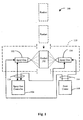
- FIG. 1 is a functional block diagram of an electrostatic spray system of the present invention.
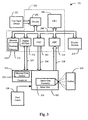
- Figure 2 is a functional block diagram of a system for testing a spray gun and for determining the spray gun's power supply operating parameters.
- Figure 3 is a functional block diagram of a system for determining a spray gun's power supply operating parameters and for storing such operating parameters and spray gun type identification information in a memory or data device.
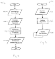
- Figure 4 is a flow chart illustrating the testing logic of the present invention for determining a spray gun's power supply operating parameters and the storage thereof, along with spray gun type identification information, in a memory or data device.
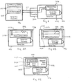
- Figures 5A, 5B, and 5C illustrate various embodiments of a memory or data device that is integral to a spray gun.
- Figure 6 is functional block diagram illustrating the relationships between a spray gun controller, spray gun, and memory device.
- Figures 7A-7E illustrate various embodiments of a memory or data device that is external to a spray gun.
- Figure 8 is a functional block diagram illustrating the relationship between a spray gun controller, a spray gun, a connector to the spray gun from the controller, and a memory or data device.
- Figure 9 is a flow chart of the logic for reading, configuring, and controlling a spray gun's power supply.
- the electrostatic spray system 100 generally includes, for example, one or more spray guns 102 and 104 that are in electric circuit communication with a spray gun controller 106. Typically, each gun is associated with its own dedicated controller 106. The circuit communication is preferably via shielded and insulated wire conductors. The one or more spray guns 102 and 104 are also in fluid communication with a powder coating material feed center 108. The fluid communication is via one or more hoses. Product or parts 112 to be sprayed or coated enter the electrostatic spray system 100 through an opening in a booth 110. In booth 110, the product 112 is sprayed by spray guns 102 and/or 104.
- the spray guns 102 and/or 104 are controlled by spray gun controller 106.
- Other components such as, for example, a compressed air source and electric power source, are typically also part of electrostatic spray system 100. More detailed examples of electrostatic spray systems are described in U.S. Patent No. 5,788,728 to Solis, U.S. Patent No. 5,743,958 to Shutic, U.S. Patent No. 5,725,670 to Wilson et al., U.S. Patent No. 5,725,161 to Hartle, which are hereby incorporated by reference.
- the electrostatic application of powder coating to the product 112 begins with fluidization. Fluidization is a process where powder being sprayed is mixed with compressed air, enabling it to be pumped from a container in the feed center 108 and supplied to the spray guns 102 and/or 104. The powder flow is regulated by controlling the air supplied to pumps associated with feed center 108. The powder supplied to the spray guns 102 and/or 104 is charged using either a corona or tribo-charging gun. Charged powder is sprayed towards the grounded product 112 by spray guns 102 and 104. When the powder particles come close to the product 112, an electrostatic attraction between the charged powder particles and the grounded product 112 adheres the powder to the product 112.
- the coated product 112 then passes through an oven (not shown) wherein the powder coating material is melted and cured. Any oversprayed powder is contained within the booth 110 and drawn into filter cartridges by a centrifugal fan (not shown). The recovered powder is then sieved and supplied back to the spray guns 102 and/or 104.
- the spray gun 102 performs several functions including, for example: directing the flow of powder; controlling the spray pattern size and shape; and imparting the electrostatic charge to the powder being sprayed. It should also be noted that electrostatic spray system 100 is shown with two spray guns 102 and 104 for exemplary purposes only. Alternative embodiments of electrostatic spray system 100 can include one or more spray guns. Hence, reference hereinafter will be made only to spray gun 102 with the understanding that such reference applies to any number of spray guns that may be present in the electrostatic spray system 100.
- the spray gun 102 is preferably one or two types: corona charging or tribo-charging.
- High voltage or low voltage cables 116 are the two preferred ways that the power is supplied to a corona-charged powder spray gun. If the high-voltage generator is internal to the gun, a low-voltage cable feeds the power supply in the gun. If the high-voltage power supply is external to the gun, a high-voltage cable extends from the power supply to the gun. Both types of guns can be negative or positive in polarity.
- corona charging uses a negative polarity high-voltage power supply because negative polarity produces more ions and is less prone to arcing than positive polarity.
- the charging electrode is held at a very high negative potential, requiring a power supply rated from about 30,000 to 100,000 volts.
- tribo is derived from the Greek word tribune, meaning to rub or produce friction.
- tribo charging the powder particles are charged by causing them to rub at a high velocity on a tribo-charging surface and thereby, transferring charge from the charging surface to the powder particles. Without a strong electrostatic field in front of the spray gun extending from the corona electrode to the part, tribo-charging virtually eliminates the well-known problem of "faraday cage effect."
- the powder particles In tribo guns, the powder particles generally take on a positive charge inside the spray gun due to the loss of electrons. The charged particles are then directed by the spray gun towards the part being coated.
- the powder particles are charged in the tribo spray gun and there is no strong electrostatic field, the powder particles do not build up on leading edges of the product 112 to be coated.
- the advantage tribo guns is the elimination of "fatty edges,” resulting in a uniform coating and even film build on the product 112.
- the powder spray gun 102 can also be either manual or automatic.
- Manual spray guns are held and triggered by a hand painter.
- manual spray gun systems include SURE COAT® Manual Spray Gun System, TRIBOMATIC® II Spray Gun, TRIBOMATIC® 500 Manual Spray Gun, TRIBOMATIC® Wand, and the TRIBOMATIC® Disc, all manufactured by Nordson Corp. of Westlake, Ohio.
- Automatic spray guns are triggered by a controller. Automatic guns may be fixed, or supported on gun movers. Examples of automatic spray gun systems include the VERSA-SPRAY® II Automatic Spray System and the VERSA-SPRAY® II PE Porcelain Enamel Spray System with SURE COAT® Control, all manufactured by Nordson Corp. of Westlake, Ohio.
- system 200 for testing a spray gun 102 and for determining the spray gun power supply operating parameters is shown. Once the operational parameters of spray gun 102 are determined, system 200 stores these parameters and gun type identification data in a memory device associated with the spray gun 102.
- the system 200 has a testing controller 202, associated user input device 222, and display device 210.
- the user input device 222 is preferably used to input alphanumerical information through a keyboard or similar keypad and/or other information that can be provided by a mouse or other pointing device(s).
- the display device 210 preferably displays information generated from the system 200 and preferably includes CRT or LCD displays.
- the testing controller 202 preferably includes a programmable CPU 204, a decoder 206, analog-to-digital converter (ADC) 212, digital-to-analog converter (DAC) 214, digital I/O port 216, and memory 218, all of which are in circuit communication with each other through data bus 208.
- the testing controller 202 may further include additional components such as, for example, external memory devices including disk drives and CD ROM, network interfaces, and device expansion ports (not shown).
- the decoder 206 decodes information input from the user input devices (e.g. , keyboard or mouse) and places such information on data bus 208.
- the ADC 212 converts analog information received from spray gun 102 on analog data bus 228 to digital information and makes such digital information available on data bus 208.
- the analog information read from the spray gun 102 includes the gun's power supply operating parameters such as, for example, minimum drive current, maximum drive current, and feedback current information.
- the minimum drive current parameter would represent the lowest level of current, for a given drive voltage, which is required for the power supply to be operation under no-load conditions.
- the maximum drive current parameter would represent the level of current required, for a given drive voltage, which is required to operate in the power supply under a specified fully loaded condition. These two parameters would define the drive current operating window for the power supply at the given drive voltage. Therefore, during normal operation, the controller would compare these parameters to the actual drive current. If the drive current falls outside of these windows, it would indicate to the controller that the power supply should be replaced. For example, if the power supply is operating with a drive current of less than the minimum required voltage to operate the power supply under no-load conditions, then there must something wrong with the power supply.
- one power supply may have a minimum drive current of 50 mA, whereas another power supply as tested has minimum drive current of 74 mA.
- the first power supply is more efficient in that it only requires 50 mA to power-up the power supply under no-load conditions, whereas the second power supply requires 75 mA to power-up that power supply under no-load conditions.
- a reading of 60 mA for the second power supply indicates a problem--since at least 75 mA are required for operation, but would not be indicative of a problem relative to the more efficient first power supply that requires only 50 mA to be operational.
- the system can more accurately determine from monitoring power supply drive current, for example, whether there is a problem with a particular power supply for an electrostatic spray gun.
- control systems in the past have had to prescribe a very wide window of acceptance for a power supply parameter such as, for example, drive current.
- a power supply parameter such as, for example, drive current.
- ADC 212 and analog data bus 228 may be in circuit communication with gun 102 through appropriate buffering and interface devices (not shown). The function of such buffering and interface devices would be to scale the analog information to levels which are appropriate for input into ADC 212.
- the DAC 214 converts digital information from testing controller 202 to analog information suitable for input to the spray gun 102 through analog data bus 230.
- DAC 214 and analog data bus 230 may be in circuit communication with spray gun 102 indirectly via appropriate buffering components (not shown).
- the information transmitted along analog data bus 230 includes drive current and/or drive voltage information which is input to the spray gun 102.
- the testing controller 202 is capable of directing testing information such as, for example, drive current and/or drive voltage and simultaneously monitoring the feedback current levels present in the spray gun 102 during operation.
- a digital I/O port 216 is in circuit communication with the spray gun 102 through digital data bus 232. So configured, purely digital information can be passed between the testing controller 202 and the spray gun 102. As will be described in more detail, such digital information includes at least a spray gun type identifier.
- the spray gun 102 has a spray gun assembly 224 and a memory device 226 associated therewith.
- the memory device 226 is integral with the spray gun 102 and includes information preferably relating to the spray gun type identification and spray gun power supply operating parameters.
- the spray gun assembly 224 preferably includes conventional spray gun components such as a power supply, electrode, grip handle or support mechanism, and fluid pathways for the flow of air entrained powder paint particles. Other components may also be present. So configured, the system 200 utilizes analog and digital information to determine the operating parameters of the spray gun 102. These operating parameters, along with the spray gun type identification, can then be stored in the memory device 226 and in database 220.
- FIG. 3 a system 300 for determining the operating parameters of the spray gun 102 and for storing the operating parameters and the spray gun type identification in memory device 226 is illustrated.
- Figure 3 is substantially similar to Figure 2 and, therefore, a discussion of the similar components will not be presented and reference should be made to the previous discussion relating to Figure 2 for such description.
- the spray gun 102 of Figure 3 includes a connector 302 that has memory device 226 integral therewith.
- the connector 226 is preferably made of a molded electrically-insulating material and interfaces the spray gun 102 with the spray gun controller 106.
- the spray gun configurations of Figures 2 and 3 provide alternative embodiments wherein the memory device 226 is integral with the spray gun 102 as shown in Figure 2 or integral with a removable connector 302 that connects to the spray gun 102 as shown in Figure 3.
- Memory devices may also be physically remote from the spray gun so long as they are logically connected with the spray gun power supply and the stored information is related thereto.
- Illustrated in Figure 4 is a flow chart showing the testing logic employed by systems 200 and 300 to determine a spray gun's power supply operating parameters of and the storage thereof, along with the spray gun type identification, in memory device 226.
- the logic starts at step 402 where the system energizes the power supply for the spray gun 102. As described above, this is accomplished by, for example, inputting a series of drive currents into the power supply at a given drive voltage to determine the minimum drive current necessary to operate the power supply at no-load conditions. The power supply is then loaded down to a fully-loaded condition and the drive current is measured and recorded to determine the maximum drive current necessary to operate the power supply under the fully-loaded condition at the given drive voltage. In step 404, these parameters are determined.
- step 408 the logic writes the maximum drive voltage and current, feedback current, and gun type identification data to memory device 226.
- the gun type identification data can be entered into the memory device 226 previous to the initiation of testing.
- the memory device 226 now includes important spray gun power supply operating parameter information and spray gun type identification information that can be subsequently read by a spray gun controller from the memory device 226.
- FIG. 5A, 5B and 5C various embodiments of memory device 226 configured integral with spray gun 102 are shown. More specifically, the memory device 226 embodiments of Figures 5A and 5B are directed to spray gun identification information. The memory device 226 embodiment of Figure 5C is directed to spray gun identification information and gun power supply operating parameter information. In each of the embodiments shown, the memory device 226 is in electric circuit communication with a connector port (not shown) that is integral to the spray gun 102.
- the connector port is preferably male ( i.e ., pins) or female ( i.e. , sockets) in configuration and adapted to be connectable to a mating cable and connector from the spray gun controller 106 or testing system 200.
- the memory device 225 includes a molded resistor 502.
- the molded resistor 502 is disposed across two pins or sockets 503 A and 503B of the spray gun 102 connector port.
- the spray gun identification information is represented by the value of the molded resistor 502.
- the spray gun controller 102 reads the resistor value, or alternatively, a voltage generated by forcing a current through the resistor 502.
- the spray gun controller 106 can use a look-up table contained within the spray gun controller logic or controller routines to determine the type of spray gun and the operating parameters that are relevant to that spray gun type. For example, a resistor value of infinity (i.e.
- open-circuit preferably indicates the absence of any type of spray gun.
- a resistor value of 1 k ⁇ can represent a first spray gun type.
- a resistor value of 10 k ⁇ can represent a second spray gun type.
- a resistor value of 100 k ⁇ can represent a third spray gun type. It should be understood from the above-description that a large, if not infinite, number of resistor and identifier combinations are available.
- this embodiment of memory device 225 includes molded serial identification bits 504 and 506.
- the molded bits are disposed across at least three pins or sockets 503C, 503D, and 503E of the spray gun 102 connector port.
- the spray gun identification information is represented by the value of the molded bits. In the case of two bits, four possible spray gun identifiers are possible: Bit 1 Bit 2 Identification 0 0 No Gun Present 0 1 Gun Type 1 1 0 Gun Type 2 1 1 Gun Type 3 A "1" bit is preferably represented by shorting a first or second pin or socket 503C, 503D with a third ground pin or socket 503E.
- a "0" bit is preferably represented by the first or second pin 503C, 503D being open-circuit with respect to pin or socket 503E.
- the spray gun controller 102 reads the bit pattern of each identification pin or socket of the spray gun 102 connector port. Based on the bit value, the spray gun controller 106 can use a look-up table contained within the spray gun controller logic or controller routines to determine the type of spray gun and the operating parameters that are relevant to it.
- this embodiment of memory device 225 includes a circuit board 508 preferably having an Electronically Erasable Programmable Read Only Memory (EEPROM) 510.
- the EEPROM 510 preferably includes at least spray gun identification information and operating parameter information.
- the spray gun identification information may take the form of two or more bits (as earlier described) or an identification code.
- the code may be in any form including binary, hexadecimal, alphabetic, numerical, and alpha-numeric. Any type of code or coding system capable of being stored within EEPROM 510 can be employed.
- the operating parameter information preferably includes the spray gun's minimum drive current at no-load conditions and the drive current required to operate the power supply at a specified fully loaded condition, both at a specified given drive voltage.
- memory device 226 can be an electronically programmable read-only memory (EPROM), programmable read-only memory (PROM) or a conventional read-only memory (ROM). So configured, the spray gun controller 102 reads the spray gun identification information and operating parameter information from the memory device 226. Based on such information, the spray gun controller 106 can use a look-up table contained within the spray gun controller logic to determine the type of spray gun
- the spray gun controller 106 includes a processing system 604 that it includes, for example, one or more microprocessors, I/O components (i.e. , ADCs, DACs, displays, keyboard/keypad etc. ), and memory devices. Additionally, spray gun controller 106 includes controller routines 602 for reading information from the memory device 226 and controlling the operation of the spray gun power supply based on the information provided from memory device 226. Additionally, controller routines 602 monitor spray gun 102 power supply parameters such as drive current, for example, to ensure that the power supply is operating properly.
- a processing system 604 that it includes, for example, one or more microprocessors, I/O components (i.e. , ADCs, DACs, displays, keyboard/keypad etc. ), and memory devices.
- spray gun controller 106 includes controller routines 602 for reading information from the memory device 226 and controlling the operation of the spray gun power supply based on the information provided from memory device 226. Additionally, controller routines 602 monitor spray gun 102 power supply parameters such
- Figures 7A-7E Illustrated in Figures 7A-7E are various embodiments of memory device 226 configured external to spray gun 102. More specifically, Figures 7A-7E illustrates embodiments of the memory device 226 integral to a connector 302 for connecting a controller cable 702 from the spray gun controller 106 to the spray gun 102.
- the connector 302 preferably includes either a male ( i.e. , pins) or female ( i.e. , sockets) physical configuration that mates with a port integral or otherwise associated with the spray gun 102.
- Illustrated in Figure 7B is an embodiment of the memory device 226 having the resistor 502 molded integral to the connector 302. So configured, molded resistor 502 is employed in the same manner as described in connection with Figure 5A. Namely, the spray gun controller 102 reads the resistor value or, alternative, a voltage generated by forcing a current through the resistor 502. Based on the resistor or voltage value, the spray gun controller 106 can use a look-up table contained within the spray gun controller logic or controller routines to determine the type of spray gun and its relevant operating parameters.
- Illustrated in Figure 7D is an embodiment of the memory device 226 having the molded serial identification bits 504 and 506 integral to the connector 302. So configured, the serial identification bits 504 and 506 are configured and employed in the same manner as described in connection with Figure 5B. Namely, the spray gun controller 102 reads the bit pattern of each identification pin or socket of the spray gun 102 connector port. Based on the bit value, the spray gun controller 106 can use a look-up table contained within the spray gun controller logic or controller routines to determine the type of spray gun and its relevant operating parameters.
- the EEPROM 510 preferably includes at least spray gun identification information and operating parameter information, which can be present in any of the several described forms (e.g. , binary, hexadecimal, alphabetic, numerical, and alpha-numeric.)
- the circuit board 508 may alternatively include EPROMs, PROMs and/or conventional ROMs.
- FIG 8 a block diagram similar to Figure 6 illustrating the relationships between, for example, the spray gun controller 106, spray gun 102, connector 302 and memory device 226 is shown.
- the present invention is applicable to existing spray guns that are not adaptable to integral memory devices such as those described by Figures 5A-5C.
- this difference is invisible to the spray gun controller 106 because the controller does not know whether the spray gun identification information and/or power supply parameter information is coming directly from the spray gun 102 or a connector 302 associated therewith.
- the logic 900 starts in step 902 where the spray gun controller 106 reads the spray gun identification and/or operating parameter information from memory device 226.
- the memory device 226 can be, for example, integral to the spray gun 102 ( i.e., Figure 6) or integral to a connector 302 associated with the spray gun 102 (i.e., Figure 8).
- the logic 900 utilizes one or more diagnostic routines (in step 904) that use the operating parameter information to monitor (in step 906) the operation of the gun power supply. If a warning or alarm condition is detected indicating an existing or imminent power supply failure, that condition is preferably represented on a spray gun controller display.
Landscapes
- Electrostatic Spraying Apparatus (AREA)
- Application Of Or Painting With Fluid Materials (AREA)
- Spray Control Apparatus (AREA)
Applications Claiming Priority (4)
| Application Number | Priority Date | Filing Date | Title |
|---|---|---|---|
| US15456099P | 1999-09-17 | 1999-09-17 | |
| US154560P | 1999-09-17 | ||
| US612847 | 2000-07-10 | ||
| US09/612,847 US6758423B1 (en) | 1999-09-17 | 2000-07-10 | Spray gun with data device and method of control |
Publications (2)
| Publication Number | Publication Date |
|---|---|
| EP1084757A2 true EP1084757A2 (fr) | 2001-03-21 |
| EP1084757A3 EP1084757A3 (fr) | 2002-08-14 |
Family
ID=26851549
Family Applications (1)
| Application Number | Title | Priority Date | Filing Date |
|---|---|---|---|
| EP00308065A Withdrawn EP1084757A3 (fr) | 1999-09-17 | 2000-09-15 | Pistolet de pulvérisation comprenant un dispositif de gestion de données et procédé de commande |
Country Status (4)
| Country | Link |
|---|---|
| US (1) | US6758423B1 (fr) |
| EP (1) | EP1084757A3 (fr) |
| JP (1) | JP2001129452A (fr) |
| CN (1) | CN1123396C (fr) |
Cited By (5)
| Publication number | Priority date | Publication date | Assignee | Title |
|---|---|---|---|---|
| WO2005075088A3 (fr) * | 2004-01-30 | 2005-12-15 | Nordson Corp | Systeme d'application de materiau a composant ayant des aptitudes a effectuer des operations d'identification sans fil |
| EP1970126A1 (fr) * | 2007-03-16 | 2008-09-17 | Sulzer Metco AG | Procédé et dispositif destinés à l'acquisition de données |
| WO2012161762A1 (fr) * | 2011-02-14 | 2012-11-29 | Illinois Tool Works Inc. | Dispositif de commande pour dispositif de revêtement par pulvérisation de poudre |
| WO2014058913A1 (fr) * | 2012-10-11 | 2014-04-17 | Finishing Brands Holdings Inc. | Système et procédé pour fabriquer une structure à l'aide d'un pulvérisateur électrostatique |
| EP3616798A4 (fr) * | 2017-04-28 | 2021-02-24 | Musashi Engineering, Inc. | Unité de câble, dispositif d'alimentation en matériau liquide et dispositif d'application dans lesquels ladite unité de câble est utilisée |
Families Citing this family (34)
| Publication number | Priority date | Publication date | Assignee | Title |
|---|---|---|---|---|
| WO2003031075A1 (fr) * | 1999-09-16 | 2003-04-17 | Nordson Corporation | Pistolet pulverisateur dote d'un bec pulverisateur a angle en ligne |
| US20050063131A1 (en) * | 2002-02-12 | 2005-03-24 | Perkins Jeffrey A. | Controller for electrostatic spray gun internal power supply |
| US20050095359A1 (en) * | 2003-10-31 | 2005-05-05 | Nordson Corporation | Hot melt adhesive system and method using machine readable information |
| ITTO20040580A1 (it) * | 2004-08-31 | 2004-11-30 | Itw Welding Products Italy Srl | Macchina saldatrice ad arco elettrico |
| ITTO20040579A1 (it) * | 2004-08-31 | 2004-11-30 | Itw Welding Products Italy Srl | Macchina saldatrice e relativo metodo di funzionamento |
| US7208699B2 (en) * | 2005-02-03 | 2007-04-24 | Illinois Tool Works Inc. | Spool gun having unitary shielding gas and weld power connector |
| US7544396B2 (en) * | 2005-03-10 | 2009-06-09 | General Electric Company | Electrostatic coating composition comprising corrosion resistant metal particulates and method for using same |
| US7601400B2 (en) * | 2005-03-10 | 2009-10-13 | General Electric Company | Liquid electrostatic coating composition comprising corrosion resistant metal particulates and method for using same |
| US7460924B2 (en) * | 2005-06-16 | 2008-12-02 | Illinois Tool Works Inc. | In-gun power supply control |
| AT502283B1 (de) * | 2005-07-15 | 2007-05-15 | Fronius Int Gmbh | Schweissverfahren und schweisssystem mit bestimmung der position des schweissbrenners |
| CN100387358C (zh) * | 2005-07-21 | 2008-05-14 | 上海交通大学 | 电弧喷涂电源数字控制系统 |
| US10144080B2 (en) | 2005-08-25 | 2018-12-04 | Lincoln Global, Inc. | Torch for electric arc welding or plasma cutting system |
| US8431862B2 (en) * | 2005-08-25 | 2013-04-30 | Lincoln Global, Inc. | Torch for electric arc welding system |
| US20070288202A1 (en) * | 2006-06-13 | 2007-12-13 | Durr Systems, Inc. | Method For Conducting Diagnostic Tests of Spray Equipment |
| DE202006021238U1 (de) | 2006-08-25 | 2014-01-29 | Baumer Hhs Gmbh | Heißleimauftragssystem |
| US20080217437A1 (en) * | 2007-03-06 | 2008-09-11 | Spraying Systems Co. | Optimized Method to Drive Electric Spray Guns |
| DE102007062132A1 (de) * | 2007-12-21 | 2009-07-02 | Dürr Systems GmbH | Testverfahren und Testgerät zur Funktionsprüfung einer Lackiereinrichtung |
| US20090212027A1 (en) * | 2008-02-21 | 2009-08-27 | Hypertherm, Inc. | Binary Signal Detection |
| US8803033B2 (en) | 2008-10-22 | 2014-08-12 | Lincoln Global, Inc. | Semi-automatic brazing device |
| DE102009029821A1 (de) | 2009-06-18 | 2010-12-23 | Focke & Co.(Gmbh & Co. Kg) | Verfahren zum Betreiben eines Beleimungssystems |
| WO2011053368A1 (fr) * | 2009-10-27 | 2011-05-05 | Siemens Aktiengesellschaft | Procédé pour simuler l'épaisseur d'un revêtement |
| JP5594118B2 (ja) * | 2010-12-16 | 2014-09-24 | パナソニック株式会社 | アーク溶接装置およびアーク溶接電源装置および溶接用トーチ |
| CN102658254A (zh) * | 2012-04-06 | 2012-09-12 | 昆山威茂电子科技有限公司 | 一种手机按键的喷涂装置 |
| JP5967647B2 (ja) * | 2012-07-13 | 2016-08-10 | アネスト岩田株式会社 | 静電塗装用エアスプレーガン、静電塗装システムおよび静電塗装方法 |
| US11815919B2 (en) | 2013-02-11 | 2023-11-14 | Graco Minnesota Inc. | Operator interface device and distributed control for fluid dispensing systems |
| US10969805B2 (en) | 2013-02-11 | 2021-04-06 | Graco Minnesota Inc. | Paint sprayer distributed control and output volume monitoring architectures |
| US11750954B2 (en) | 2013-02-11 | 2023-09-05 | Graco Minnesota Inc. | Remote monitoring for fluid applicator system |
| US10390601B2 (en) * | 2014-01-05 | 2019-08-27 | Je Matadi, Inc | System and method for applying cosmetics |
| US20190201927A1 (en) * | 2017-12-29 | 2019-07-04 | E-Mist Innovations, Inc. | Electrostatic sprayer |
| CN118179785A (zh) * | 2019-01-18 | 2024-06-14 | 瓦格纳喷涂技术有限公司 | 喷涂系统的智能控制 |
| US11311958B1 (en) * | 2019-05-13 | 2022-04-26 | Airgas, Inc. | Digital welding and cutting efficiency analysis, process evaluation and response feedback system for process optimization |
| US11513602B2 (en) | 2019-09-10 | 2022-11-29 | Wagner Spray Tech Corporation | Gesture control of a fluid application system |
| US12605735B2 (en) | 2021-09-08 | 2026-04-21 | Pella Corporation | Dispensing system with controlled delivery and associated methods |
| CN116237175A (zh) * | 2022-12-15 | 2023-06-09 | 南昌市普辉实业有限公司 | 一种铝型材静电喷涂自动控制方法 |
Citations (8)
| Publication number | Priority date | Publication date | Assignee | Title |
|---|---|---|---|---|
| US5725670A (en) | 1994-02-18 | 1998-03-10 | Nordson Corporation | Apparatus for powder coating welded cans |
| US5725161A (en) | 1995-02-28 | 1998-03-10 | Nordson Corporation | Electrostatic coating system including improved spray gun for conductive paints |
| US5743958A (en) | 1993-05-25 | 1998-04-28 | Nordson Corporation | Vehicle powder coating system |
| US5788728A (en) | 1996-12-03 | 1998-08-04 | Nordson Corporation | Powder coating booth with improved cyclone separator |
| US5816508A (en) | 1995-05-19 | 1998-10-06 | Nordson Corporation | Powder spray gun with rotary distributor |
| US5904294A (en) | 1996-09-13 | 1999-05-18 | Nordson Corporation | Particle spray apparatus and method |
| US5908162A (en) | 1998-02-25 | 1999-06-01 | Nordson Corporation | Spray gun having an anti-back-ionization probe with a control system therefor |
| US5938126A (en) | 1998-03-23 | 1999-08-17 | Nordson Corporation | Spray gun having a current monitored anti-back-ionization probe |
Family Cites Families (13)
| Publication number | Priority date | Publication date | Assignee | Title |
|---|---|---|---|---|
| FR2266450B1 (fr) | 1974-04-04 | 1978-08-04 | Lestradet M C J | |
| CH620600A5 (fr) * | 1977-05-12 | 1980-12-15 | Alex Hengartner | |
| EP0058472B1 (fr) | 1981-02-12 | 1986-04-23 | Imperial Chemical Industries Plc | Pulvérisateur agricole et réservoir à employer avec celui-ci |
| FR2552345B1 (fr) * | 1983-09-27 | 1985-12-20 | Sames Sa | Appareillage de peinture electrostatique a pulverisateur pneumatique sur support mobile, reglable en fonctionnement |
| JPH053234Y2 (fr) * | 1985-06-11 | 1993-01-26 | ||
| US5060860A (en) * | 1989-08-18 | 1991-10-29 | Hughes Aircraft Company | Paint conductivity measurement system |
| US5741558A (en) * | 1993-04-07 | 1998-04-21 | Nordson Corporation | Method and apparatus for coating three dimensional articles |
| EP0676242A3 (fr) * | 1994-03-31 | 1996-06-05 | Sames Sa | Procédé et dispositif de projection électrostatique de produit de revêtement. |
| US5718767A (en) | 1994-10-05 | 1998-02-17 | Nordson Corporation | Distributed control system for powder coating system |
| FR2736772B1 (fr) | 1995-07-10 | 1997-08-22 | Sames Sa | Procedes, dispositif d'elaboration de haute tension et installation de projection electrostatique de produit de revetement |
| JPH0948120A (ja) * | 1995-08-09 | 1997-02-18 | Mita Ind Co Ltd | 記録ヘッド及びインクジェット記録装置 |
| US6126265A (en) | 1997-01-21 | 2000-10-03 | Hewlett-Packard Company | Ink jet printer service station controlled by data from consumable parts with incorporated memory devices |
| US5972417A (en) * | 1997-11-14 | 1999-10-26 | Nordson Corporation | Spray gun power supply monitor |
-
2000
- 2000-07-10 US US09/612,847 patent/US6758423B1/en not_active Expired - Lifetime
- 2000-09-14 JP JP2000279744A patent/JP2001129452A/ja active Pending
- 2000-09-15 EP EP00308065A patent/EP1084757A3/fr not_active Withdrawn
- 2000-09-18 CN CN00124842A patent/CN1123396C/zh not_active Expired - Fee Related
Patent Citations (8)
| Publication number | Priority date | Publication date | Assignee | Title |
|---|---|---|---|---|
| US5743958A (en) | 1993-05-25 | 1998-04-28 | Nordson Corporation | Vehicle powder coating system |
| US5725670A (en) | 1994-02-18 | 1998-03-10 | Nordson Corporation | Apparatus for powder coating welded cans |
| US5725161A (en) | 1995-02-28 | 1998-03-10 | Nordson Corporation | Electrostatic coating system including improved spray gun for conductive paints |
| US5816508A (en) | 1995-05-19 | 1998-10-06 | Nordson Corporation | Powder spray gun with rotary distributor |
| US5904294A (en) | 1996-09-13 | 1999-05-18 | Nordson Corporation | Particle spray apparatus and method |
| US5788728A (en) | 1996-12-03 | 1998-08-04 | Nordson Corporation | Powder coating booth with improved cyclone separator |
| US5908162A (en) | 1998-02-25 | 1999-06-01 | Nordson Corporation | Spray gun having an anti-back-ionization probe with a control system therefor |
| US5938126A (en) | 1998-03-23 | 1999-08-17 | Nordson Corporation | Spray gun having a current monitored anti-back-ionization probe |
Cited By (8)
| Publication number | Priority date | Publication date | Assignee | Title |
|---|---|---|---|---|
| WO2005075088A3 (fr) * | 2004-01-30 | 2005-12-15 | Nordson Corp | Systeme d'application de materiau a composant ayant des aptitudes a effectuer des operations d'identification sans fil |
| EP1970126A1 (fr) * | 2007-03-16 | 2008-09-17 | Sulzer Metco AG | Procédé et dispositif destinés à l'acquisition de données |
| US7992799B2 (en) | 2007-03-16 | 2011-08-09 | Sulzer Metco Ag | Device and method for the management of data |
| WO2012161762A1 (fr) * | 2011-02-14 | 2012-11-29 | Illinois Tool Works Inc. | Dispositif de commande pour dispositif de revêtement par pulvérisation de poudre |
| US9703297B2 (en) | 2011-02-14 | 2017-07-11 | Gema Switzerland Gmbh | Control device for a powder spray coating device |
| WO2014058913A1 (fr) * | 2012-10-11 | 2014-04-17 | Finishing Brands Holdings Inc. | Système et procédé pour fabriquer une structure à l'aide d'un pulvérisateur électrostatique |
| EP3616798A4 (fr) * | 2017-04-28 | 2021-02-24 | Musashi Engineering, Inc. | Unité de câble, dispositif d'alimentation en matériau liquide et dispositif d'application dans lesquels ladite unité de câble est utilisée |
| US11456564B2 (en) | 2017-04-28 | 2022-09-27 | Musashi Engineering, Inc. | Cable unit, and liquid material supply device and application device in which said cable unit is used |
Also Published As
| Publication number | Publication date |
|---|---|
| US6758423B1 (en) | 2004-07-06 |
| CN1123396C (zh) | 2003-10-08 |
| JP2001129452A (ja) | 2001-05-15 |
| CN1321549A (zh) | 2001-11-14 |
| EP1084757A3 (fr) | 2002-08-14 |
Similar Documents
| Publication | Publication Date | Title |
|---|---|---|
| US6758423B1 (en) | Spray gun with data device and method of control | |
| EP1084756A2 (fr) | Système de revêtement comprenant un panneau de commande centralisé et une cartographie des pistolets | |
| US5678770A (en) | Powder coating spray gun with resettable voltage multiplier | |
| EP0160179A2 (fr) | Générateur de haute tension pour appareil de pulvérisation électrostatique | |
| US5622563A (en) | Nonincedive rotary atomizer | |
| KR100380264B1 (ko) | 부품에파우더코팅을하는파우더코팅시스템 | |
| EP0600397B1 (fr) | Atomiseur rotatif anti-étincelles | |
| KR101513957B1 (ko) | 정전 도장 장치 | |
| US6437963B1 (en) | Method and apparatus for controlling power supplied to an electrostatic device | |
| US5102046A (en) | Color change systems for electrostatic spray coating apparatus | |
| WO2010068353A1 (fr) | Système et procédé de surveillance haute tension pour des systèmes de revêtement par pulvérisation | |
| EP2910310B1 (fr) | Dispositif de revêtement électrostatique et procédé d'inspection de l'état fondamental | |
| US6144570A (en) | Control system for a HVDC power supply | |
| WO2006138073A1 (fr) | Dispositif et procédé de commande d’alimentation de pistolet | |
| CN100421810C (zh) | 静电涂装装置 | |
| CA1288295C (fr) | Methode de commande operationnelle d'une installation de pistolage electrostatique | |
| US5972417A (en) | Spray gun power supply monitor | |
| US20050063131A1 (en) | Controller for electrostatic spray gun internal power supply | |
| JPH08266946A (ja) | 静電スプレー塗装装置及び方法 | |
| US5861060A (en) | Supply tank for electrostatic spraying system | |
| US20020088397A1 (en) | Coating system with centralized control panel and gun mapping | |
| US20060097071A1 (en) | Self-contained powder coating system | |
| JP4638976B2 (ja) | 吹付塗装装置 | |
| CN104126129B (zh) | 静电涂装电缆维护装置 | |
| US6734679B2 (en) | Device for detecting a flow of powder particles |
Legal Events
| Date | Code | Title | Description |
|---|---|---|---|
| PUAI | Public reference made under article 153(3) epc to a published international application that has entered the european phase |
Free format text: ORIGINAL CODE: 0009012 |
|
| AK | Designated contracting states |
Kind code of ref document: A2 Designated state(s): AT BE CH CY DE DK ES FI FR GB GR IE IT LI LU MC NL PT SE |
|
| AX | Request for extension of the european patent |
Free format text: AL;LT;LV;MK;RO;SI |
|
| PUAL | Search report despatched |
Free format text: ORIGINAL CODE: 0009013 |
|
| AK | Designated contracting states |
Kind code of ref document: A3 Designated state(s): AT BE CH CY DE DK ES FI FR GB GR IE IT LI LU MC NL PT SE |
|
| AX | Request for extension of the european patent |
Free format text: AL;LT;LV;MK;RO;SI |
|
| 17P | Request for examination filed |
Effective date: 20030213 |
|
| AKX | Designation fees paid |
Designated state(s): CH DE ES FR GB IT LI |
|
| 17Q | First examination report despatched |
Effective date: 20040524 |
|
| 17Q | First examination report despatched |
Effective date: 20040524 |
|
| GRAP | Despatch of communication of intention to grant a patent |
Free format text: ORIGINAL CODE: EPIDOSNIGR1 |
|
| STAA | Information on the status of an ep patent application or granted ep patent |
Free format text: STATUS: THE APPLICATION IS DEEMED TO BE WITHDRAWN |
|
| 18D | Application deemed to be withdrawn |
Effective date: 20091204 |