EP1085184A2 - Vorrichtung und Verfahren zur Veränderung der Verdichtung einer Hubkolbenbrennkraftmaschine - Google Patents
Vorrichtung und Verfahren zur Veränderung der Verdichtung einer Hubkolbenbrennkraftmaschine Download PDFInfo
- Publication number
- EP1085184A2 EP1085184A2 EP00117326A EP00117326A EP1085184A2 EP 1085184 A2 EP1085184 A2 EP 1085184A2 EP 00117326 A EP00117326 A EP 00117326A EP 00117326 A EP00117326 A EP 00117326A EP 1085184 A2 EP1085184 A2 EP 1085184A2
- Authority
- EP
- European Patent Office
- Prior art keywords
- piston
- sleeve
- connecting rod
- locking element
- cylinder unit
- Prior art date
- Legal status (The legal status is an assumption and is not a legal conclusion. Google has not performed a legal analysis and makes no representation as to the accuracy of the status listed.)
- Withdrawn
Links
Images


Classifications
-
- F—MECHANICAL ENGINEERING; LIGHTING; HEATING; WEAPONS; BLASTING
- F02—COMBUSTION ENGINES; HOT-GAS OR COMBUSTION-PRODUCT ENGINE PLANTS
- F02B—INTERNAL-COMBUSTION PISTON ENGINES; COMBUSTION ENGINES IN GENERAL
- F02B75/00—Other engines
- F02B75/04—Engines with variable distances between pistons at top dead-centre positions and cylinder heads
- F02B75/045—Engines with variable distances between pistons at top dead-centre positions and cylinder heads by means of a variable connecting rod length
Definitions
- the invention relates to a device for changing the compression of a Reciprocating internal combustion engine according to the preamble of claim 1 and a method to change the compression of a reciprocating internal combustion engine according to Preamble of claim 9.
- DE 197 03 948 C1 discloses a device with a connecting rod, in the a large connecting rod eye associated with a crankshaft rotatably arranged a sleeve is.
- the sleeve has a crankshaft through opening arranged eccentrically to the large connecting rod eye and two circumferential edge flanges overlapping the connecting rods.
- the Compression of the reciprocating internal combustion engine is due to a change in Rotational position of the sleeve possible, the sleeve in the respective rotational position by means of one which can be brought into engagement with locking recesses in the edge flanges Locking member can be locked, which is part of a locking device.
- the locking member is connected to a lever which can be pivoted about an axis and is guided by a cam device so that it occupy two positions can, the locking member in a first position in the Locking recess of the first edge flange of the sleeve and in the other Position engages in the locking recess in the other edge flange. Because of the complex mechanics for moving the locking member are the cost of Device up. In addition, the parts are subject to the locking device mechanical wear, which adversely affects the functional reliability of the Device can impact.
- This is characterized in that the locking element with the help a piston and cylinder unit is displaceable.
- the locking element with a piston of the piston and cylinder unit coupled, which is guided displaceably in a cylinder attached to the connecting rod and divided the cylinder into two work rooms.
- the piston and Cylinder unit the piston is displaced relative to the cylinder, whereby the Locking element in the direction of the sleeve in a locking position or in opposite direction is disengaged from the sleeve.
- the locking element is coupled to the cylinder, which is relatively movable compared to the piston attached to the connecting rod.
- the device is subject to very little wear, so that a high level of functional reliability can be guaranteed.
- the piston and cylinder unit simple and compact structure can be realized.
- An embodiment of the device is particularly preferred which is characterized by distinguishes that the piston and cylinder unit is a hydraulic piston and Cylinder unit is, that is, that to move the piston relative to the Cylinder or the cylinder relative to the piston at least one the working spaces of the cylinder with a pressurized fluid, for example Pressure oil from the engine lubricating oil circuit, can be acted upon.
- a pressurized fluid for example Pressure oil from the engine lubricating oil circuit
- the pushing back and forth the piston in the cylinder can be realized, for example, that the Workrooms are filled alternately with the pressure medium.
- Another one The embodiment of the device is the piston and cylinder unit with compressed air operated, the structure and mode of operation essentially with that of the hydraulic Piston and cylinder unit matches.
- a compressive force acting spring element for example a compression spring
- the Spring element serves the piston and thereby also that connected to the piston Locking element in the depressurized state of the piston and cylinder unit or at Falling below a threshold pressure of that in the other work space Relocate the print medium independently.
- the arrangement of the spring element in the cylinder can be chosen so that it is the locking element out of engagement with the sleeve brings so that a rotation of the sleeve to change the compression of the Reciprocating internal combustion engine is possible.
- the locking element from the spring element for fixing the rotational position of the sleeve into a through opening, blind hole or open-edged recess in the sleeve crowded is advantageous in these embodiments that only for one of the two Working spaces of the cylinder a pressure medium supply is required, which the Structure of the device can be simplified.
- Claim 9 has.
- the procedure for changing the compression of a Reciprocating piston internal combustion engine in which one for the determination of the rotational position is large Connecting rod eye of a connecting rod rotatably arranged sleeve at least one with the sleeve engageable locking element is used, that the Locking element is displaced by means of a gaseous or fluid pressure medium.
- the process is characterized by a high level of functional reliability and enables a simple structure of a device used for this.
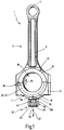
- FIG. 1 shows an embodiment of a device 1 in a perspective view to change the compression of a reciprocating internal combustion engine, namely a Connecting rod 3, which has a small connecting rod eye 5 for mounting a piston pin and a large one Connecting rod eye 7 for supporting a connecting rod bearing journal of a crankshaft.
- the Connecting rod 3 is in two parts to form a split bearing for the connecting rod bearing journal formed and comprises a connecting rod upper part 9 and a connecting rod lower part 11, which means by not shown fasteners are releasably connectable.
- the big connecting rod eye 7 is a two-part sleeve 13 is arranged, the first bearing shell 15 and one second bearing shell 17.
- the preferably made of steel, at her Inner circumference coated with a bearing material sleeve 13 has a crankshaft through opening 19, which is arranged eccentrically to the large connecting rod eye 7.
- the Bearing shells 15, 17 of the sleeve 13 rotatable in the connecting rod eye 7 are on it Outside shaped differently, which will be discussed in more detail below.
- FIG. 4 shows a perspective illustration of the one described with reference to FIG. 1 first bearing shell 15 of the sleeve 13, the outer contour partially to the Inner contour of the large connecting rod eye 7 is adapted.
- the inner contour of the connecting rod eye 7 is uniform over its entire circumference, as can be seen from FIGS. 2 and 3, each of which is a perspective view of the connecting rod upper part 9 or the connecting rod lower part 11 emerges without the sleeve 13.
- FIGS. 2 and 3 each of which is a perspective view of the connecting rod upper part 9 or the connecting rod lower part 11 emerges without the sleeve 13.
- FIGS. 2 and 3 each of which is a perspective view of the connecting rod upper part 9 or the connecting rod lower part 11 emerges without the sleeve 13.
- Appropriately adapted grooves 21 are introduced with different depths, whereby a first bearing shoulder 23 and a second bearing shoulder 25 are formed.
- the first bearing shell 15 contact surfaces 27 and 27 'with which they are in the assembled state abuts
- Figure 5 shows a perspective view of the second bearing shell 17 of the sleeve 13 obliquely from above.
- the second bearing shell 17 is completely adapted on its outer contour to the inner contour of the large connecting rod eye 7, like the first bearing shell 15, and has stop surfaces 29 and 29 ', which in the assembled state of the sleeve 13 on the contact surface 27 and 27' of the first Bearing shell 15 abut.
- stop surfaces 29, 29 ' open-edge depressions 31 and 31' are provided, which are provided for distributing a printing medium.
- the stop surfaces 29, 29 also act the second bearing shell 17 together with a stop 35 shown in Figure 3, which is formed here by a stop plate 37.
- the stop plate 37 is arranged between the upper and lower connecting rod parts and has stop surface regions 38 and 38 'protruding into the connecting rod eye 7, shown in dashed lines in FIG. 3, which interact with the stop surfaces 29, 29' of the second bearing shell 17.
- the top 49 of one of the stop surface areas 38, 38 ′ forms a first piston surface for a first working chamber 45, which is formed between the outer back of the first bearing shell 15 and the connecting rod lower part 11.
- the underside 50 of the other stop surface area forms a second piston surface for a second working chamber 47, which is formed between the outer back of the first bearing shell 15 and the connecting rod upper part 9.
- the sleeve is 13 Can be rotated by approximately 175 ° in the connecting rod eye 7, the two rotational positions of the sleeve 13 are determined by the stop 35.
- the Angular range of the sleeve 13 determined by the thickness of the stop 35.
- the second bearing shell 17 strikes with a their stop surfaces 29, 29 'from above against the stop 35 or the Stop surface areas 38, 38 'and in the other, opposite the first rotational position rotated clockwise by approximately 175 ° from the bottom against the Stop surface areas 38, 38 '.
- annular groove sections 41 and 43 are introduced, which extend in the circumferential direction of the crankshaft penetration opening 19 and extend through the stop surfaces 29, 29 'into the respective recess 31, 31'.
- the annular groove sections 41, 43 form collecting chambers which can be acted upon by a pressure medium.
- the cavity located in the assembled state between the bearing shell 15 and the connecting rod lower part 11 and the connecting rod upper part 9 represents the working chamber 45 and 47, respectively.
- the working chambers 45, 47 are circumferential by the stop plate 37 and the stop surfaces 29, 29 or the depressions 31, 31 limited.
- the working chambers 45, 47 are with pressure oil can be loaded from the engine lubricating oil circuit, the working chambers 45, 47 have separate pressurized oil supplies.
- the pressure oil supply for example via a multi-way valve, not shown in the figures, and two main oil galleries in a crankcase receiving the crankshaft with tap holes to the Main crankshaft bearings realized.
- the crankshaft main bearings are above each at least one channel in the crankshaft with the connecting rod bearing journals and arranged in this channel openings with the working chambers 45, 47 in Flow connection.
- the device 1 also includes a locking device 52 with one in the Figures 1 and 6 shown locking element 51, here on the connecting rod lower 11th is arranged and serves the sleeve 13 against in its two rotational positions Secure twisting.
- a hydraulic piston and Cylinder unit 54 is provided to move the locking element 51 in the direction of the Sleeve 13 and in the opposite direction.
- the locking element 51 perpendicular to the longitudinal central axis of the connecting rod eye 7 or arranged to the crankshaft axis of rotation and in the direction of a Double arrow 57 relocatable.
- the locking element 51 is of one here cylindrical locking bolt 55 formed in one piece with a piston 53 of the Piston and cylinder unit 54 is formed.
- the locking bolt 55 engages in one first functional position in one of the circumference of the first bearing shell 15 introduced through openings 59, 61 or into a through opening 60 in the second bearing shell 17 (FIG. 5).
- Locking bolt 55 moved out of the through opening 59, 60, 61, so that the sleeve 13 is rotatable.
- 61 of the Locking bolt 55 is retractable to prevent rotation of the sleeve 13 is dependent from the respective rotational position of the sleeve 13.
- the piston 53 divides a cylinder 63, which is attached here to the connecting rod lower part 11 Piston and cylinder unit 54 in two working spaces 65 and 67, of which the Working space 65 can be acted upon with a hydraulic pressure medium.
- the exemplary embodiment is the pressure oil from the engine lubricating oil circuit as the pressure medium used.
- a compression spring Spring element 69 is arranged, which falls below a certain pressure (Threshold pressure) in the working space 65 displaces the piston 53 within the cylinder 63 so that the locking bolt 55 is displaced away from the sleeve 13 and, if necessary, from one of the through openings 59, 60, 61 is pulled out.
- this is Locking element arranged parallel to the axis of rotation of the crankshaft and engages in one in one of the bearing shoulders of the two bearing shells 15, 17 of the sleeve 13 introduced recess.
- the rotational position of the sleeve 13 shown in FIG. 1 corresponds to the minimum compression of the reciprocating piston internal combustion engine. In this Rotational position abuts the second bearing shell 17 against the stop 35 from above Rotation of the sleeve 13 clockwise (arrow 72) in its second rotational position, in the the second bearing shell 17 abuts the stop 35 from below, it will Locking element 51 out of engagement with the sleeve 13 or the Bearing cups 15, 17 brought.
- the device 1 described with reference to the figures is characterized in particular by a cost-effective construction and also has a high level of functional reliability.
Landscapes
- Engineering & Computer Science (AREA)
- Chemical & Material Sciences (AREA)
- Combustion & Propulsion (AREA)
- Mechanical Engineering (AREA)
- General Engineering & Computer Science (AREA)
- Shafts, Cranks, Connecting Bars, And Related Bearings (AREA)
- Output Control And Ontrol Of Special Type Engine (AREA)
Abstract
Description
- Figur 1
- eine perspektivische Darstellung eines Ausführungsbeispiels eines mehrteiligen Pleuels einer Hubkolbenbrennkraftmaschine;
- Figur 2
- eine perspektivische Darstellung eines Oberteils des in Figur 1 dargestellten Pleuels;
- Figur 3
- eine perspektivische Darstellung eines Unterteils des in Figur 1 dargestellten Pleuels;
- Figur 4
- eine perspektivische Darstellung eines ersten Teils eines Ausführungsbeispiels einer mehrteiligen Lagerhülse;
- Figur 5
- eine perspektivische Darstellung eines zweiten Teils der Lagerhülse und
- Figur 6
- eine Seitenansicht eines Ausführungsbeispiels eines Verriegelungselements zur Verdrehsicherung der Lagerhülse.
Claims (9)
- Vorrichtung zur Veränderung der Verdichtung einer Hubkolbenbrennkraftmaschine mit mindestens einem Pleuel, in dessen einer Kurbelwelle zuordenbaren Pleuelauge eine Hülse mit einer Kurbelwellen-Durchgriffsöffnung verdrehbar angeordnet ist, wobei die Kurbelwellen-Durchgriffsöffnung exzentrisch zum Pleuelauge angeordnet ist, und mit einer mindestens ein mit der Hülse zu deren Drehstellungsfestlegung in Eingriff bringbares Verriegelungselement umfassenden Verriegelungseinrichtung, dadurch gekennzeichnet, daß das Verriegelungselement (51) mit Hilfe einer Kolben- und Zylindereinheit (54) verlagerbar ist.
- Vorrichtung nach Anspruch 1, dadurch gekennzeichnet, daß die Kolben- und Zylindereinheit (54) eine pneumatische Kolben- und Zylindereinheit oder hydraulische Kolben- und Zylindereinheit ist.
- Vorrichtung nach Anspruch 1 oder 2, dadurch gekennzeichnet, daß das Verriegelungselement (51) mit einem einen Zylinder (63) der Kolben- und Zylindereinheit (54) in zwei Arbeitsräume (65;67) unterteilenden Kolben (53) gekoppelt ist.
- Vorrichtung nach einem der vorhergehenden Ansprüche, dadurch gekennzeichnet, daß mindestens einer der Arbeitsräume (65;67) mit einem unter Druck stehenden hydraulischen Medium, vorzugsweise Schmieröl, beaufschlagbar ist.
- Vorrichtung nach einem der vorhergehenden Ansprüche, dadurch gekennzeichnet, daß in mindestens einem Arbeitsraum (65;67) mindestens ein den Kolben (53) mit einer Druckkraft beaufschlagendes Federelement (69) angeordnet ist.
- Vorrichtung nach einem der vorhergehenden Ansprüche, dadurch gekennzeichnet, daß das Verriegelungselement (51) bei Unterschreiten eines Schwelldrucks des Druckmediums im Arbeitsraum (65;67) mit Hilfe des Federelements (69) außer Eingriff mit der Hülse (13) verlagerbar ist.
- Vorrichtung nach einem der vorhergehenden Ansprüche, dadurch gekennzeichnet, daß das Verriegelungselement (51) parallel oder radial zur Kurbelwellendrehachse verlagerbar ist.
- Vorrichtung nach einem der vorhergehenden Ansprüche, dadurch gekennzeichnet, daß das Verriegelungselement (51) und der Kolben (53) von einem Zuführungskanal (Durchgangsbohrung (71)) für das Druckmedium durchdrungen sind, über den mindestens einem der Arbeitsräume (65;67) das Druckmedium zuführbar ist.
- Verfahren zur Veränderung der Verdichtung einer Hubkolbenbrennkraftmaschine, bei dem zur Drehstellungsfestlegung einer in einem einer Kurbelwelle zugeordneten Pleuelauge eines Pleuels verdrehbar angeordneten Hülse mindestens ein Verriegelungselement in Eingriff mit der Hülse gebracht wird, dadurch gekennzeichnet, daß das Verriegelungselement mittels eines gasförmigen oder fluiden Druckmittels verlagert wird.
Applications Claiming Priority (2)
| Application Number | Priority Date | Filing Date | Title |
|---|---|---|---|
| DE19944669 | 1999-09-17 | ||
| DE1999144669 DE19944669A1 (de) | 1999-09-17 | 1999-09-17 | Vorrichtung und Verfahren zur Veränderung der Verdichtung einer Hubkolbenbrennkraftmaschine |
Publications (2)
| Publication Number | Publication Date |
|---|---|
| EP1085184A2 true EP1085184A2 (de) | 2001-03-21 |
| EP1085184A3 EP1085184A3 (de) | 2002-03-27 |
Family
ID=7922421
Family Applications (1)
| Application Number | Title | Priority Date | Filing Date |
|---|---|---|---|
| EP00117326A Withdrawn EP1085184A3 (de) | 1999-09-17 | 2000-08-21 | Vorrichtung und Verfahren zur Veränderung der Verdichtung einer Hubkolbenbrennkraftmaschine |
Country Status (2)
| Country | Link |
|---|---|
| EP (1) | EP1085184A3 (de) |
| DE (1) | DE19944669A1 (de) |
Cited By (2)
| Publication number | Priority date | Publication date | Assignee | Title |
|---|---|---|---|---|
| US10815909B2 (en) | 2017-05-05 | 2020-10-27 | Ford Global Technologies, Llc | Method for varying a cylinder-specific compression ratio of an applied-ignition internal combustion engine and internal combustion engine for carrying out a method of said type |
| CN112714821A (zh) * | 2018-09-25 | 2021-04-27 | 曼恩能源方案有限公司 | 用于调整内燃机的缸体的连杆的长度的装置和方法 |
Families Citing this family (8)
| Publication number | Priority date | Publication date | Assignee | Title |
|---|---|---|---|---|
| DE10211971A1 (de) * | 2002-03-19 | 2003-10-02 | Bayerische Motoren Werke Ag | Vorrichtung zur Veränderung eines Verdichtungsverhältnisses einer Hubkolben-Brennkraftmaschine |
| DE10218740A1 (de) * | 2002-04-26 | 2003-11-13 | Bayerische Motoren Werke Ag | Vorrichtung zur Veränderung eines Verdichtungsverhältnisses einer Hubkolben-Brennkraftmaschine |
| DE10218744A1 (de) * | 2002-04-26 | 2003-11-13 | Bayerische Motoren Werke Ag | Vorrichtung zur Veränderung eines Verdichtungsverhältnisses einer Hubkolben-Brennkraftmaschine |
| DE10230427A1 (de) * | 2002-07-06 | 2004-01-15 | Bayerische Motoren Werke Ag | Schaltvorrichtung für einen Kurbeltrieb einer Brennkraftmaschine |
| DE10230429A1 (de) * | 2002-07-06 | 2004-01-15 | Bayerische Motoren Werke Ag | Exzenter-Verstellvorrichtung für einen Kurbeltrieb |
| DE10230428A1 (de) * | 2002-07-06 | 2004-01-15 | Bayerische Motoren Werke Ag | Exzenter-Verstellvorrichtung für einen Kurbeltrieb |
| DE102008031992B4 (de) * | 2008-07-07 | 2015-02-12 | Audi Ag | Vorrichtung zum Verstellen und Arretieren einer Exzenterbuchse in einem Lagerauge eines Pleuels einer Brennkraftmaschine |
| DE102018210265B4 (de) | 2018-06-25 | 2022-04-21 | Ford Global Technologies, Llc | Kolben für eine Brennkraftmaschine und Verfahren zum Betreiben einer Brennkraftmaschine mit einem derartigen Kolben |
Family Cites Families (8)
| Publication number | Priority date | Publication date | Assignee | Title |
|---|---|---|---|---|
| BE384807A (de) * | ||||
| US4140091A (en) * | 1977-03-09 | 1979-02-20 | Showers Jr Lewis M | Uniform compression piston engine |
| DE69108572T2 (de) * | 1990-01-17 | 1995-08-17 | Mitsubishi Motors Corp | Vorrichtung zum Ändern des Kompressionverhältnisses für Brennkraftmaschine. |
| DE4226361C2 (de) * | 1992-08-10 | 1996-04-04 | Alex Zimmer | Brennkraftmaschine |
| JPH0828314A (ja) * | 1994-07-13 | 1996-01-30 | Honda Motor Co Ltd | 内燃機関の可変圧縮比装置 |
| DE4444555A1 (de) * | 1994-12-01 | 1996-06-05 | Wronna Werner Dipl Ing | Verbrennungsmotor |
| DE19703948C1 (de) * | 1997-02-03 | 1998-06-18 | Meta Motoren Energietech | Vorrichtung zur Veränderung der Verdichtung einer Hubkolbenbrennkraftmaschine |
| DE19844200A1 (de) * | 1998-09-26 | 1999-06-17 | Victor Prof Dr Ing Gheorghiu | Kurbeltrieb für variable Verdichtung |
-
1999
- 1999-09-17 DE DE1999144669 patent/DE19944669A1/de not_active Withdrawn
-
2000
- 2000-08-21 EP EP00117326A patent/EP1085184A3/de not_active Withdrawn
Cited By (4)
| Publication number | Priority date | Publication date | Assignee | Title |
|---|---|---|---|---|
| US10815909B2 (en) | 2017-05-05 | 2020-10-27 | Ford Global Technologies, Llc | Method for varying a cylinder-specific compression ratio of an applied-ignition internal combustion engine and internal combustion engine for carrying out a method of said type |
| CN112714821A (zh) * | 2018-09-25 | 2021-04-27 | 曼恩能源方案有限公司 | 用于调整内燃机的缸体的连杆的长度的装置和方法 |
| US11352948B2 (en) | 2018-09-25 | 2022-06-07 | Man Energy Solutions Se | Apparatus and method for adjusting the length of a connecting rod of a cylinder of an internal combustion engine |
| CN112714821B (zh) * | 2018-09-25 | 2022-09-13 | 曼恩能源方案有限公司 | 用于调整内燃机的缸体的连杆的长度的装置和方法 |
Also Published As
| Publication number | Publication date |
|---|---|
| EP1085184A3 (de) | 2002-03-27 |
| DE19944669A1 (de) | 2001-03-22 |
Similar Documents
| Publication | Publication Date | Title |
|---|---|---|
| DE19703948C1 (de) | Vorrichtung zur Veränderung der Verdichtung einer Hubkolbenbrennkraftmaschine | |
| DE3818357C2 (de) | ||
| DE4235934C2 (de) | Ventilantriebsvorrichtung | |
| DE102007010148A1 (de) | Ventiltrieb für Gaswechselventile einer Brennkraftmaschine mit einem axial beweglichen Lager | |
| WO2008058836A1 (de) | Hubübertragungsbauteil und verfahren zu dessen herstellung | |
| DE3415245A1 (de) | Ventilbetaetigungsmechanismus fuer eine brennkraftmaschine | |
| DE102016114978A1 (de) | Pleuel für eine Brennkraftmaschine mit variabler Verdichtung | |
| DE69421170T2 (de) | Nockenspitze mit exzentrischer drehbewegung | |
| EP1085184A2 (de) | Vorrichtung und Verfahren zur Veränderung der Verdichtung einer Hubkolbenbrennkraftmaschine | |
| DE10151518A1 (de) | Verriegelungsmechanismus I für eine Pleuelstange mit variablem Verdichtungsverhältnis | |
| DE3730655C2 (de) | ||
| EP1205652B1 (de) | Variables Kompressionsverhältnis, zwei durch Öldruck betätigte Ventile in der Kurbelwelle | |
| DE10151507A1 (de) | Hydraulikkreis zum Entriegeln von Verriegelungsmechanismen für Pleuelstangen mit variablem Verdichtungsverhältnis | |
| EP1085185A2 (de) | Vorrichtung zur Veränderung der Verdichtung einer Hubkolbenbrennkraftmaschine | |
| DE102015103206B4 (de) | Pleuelstange mit einer Exzenter-Verstelleinrichtung und Verbrennungsmotor mit einstellbarem Verdichtungsverhältnis | |
| DE3720947A1 (de) | Nockenwellenanordnung | |
| DE102018124697A1 (de) | VCR-Hubkolbenmaschine | |
| CH672173A5 (de) | ||
| DE10309651A1 (de) | Hubkolbenmaschine | |
| EP2090757B1 (de) | Kipphebelanordnung mit einer Nuten aufweisenden Lagerschale | |
| DE102019115994A1 (de) | Pleuel einer Verbrennungskraftmaschine zur Änderung des Verdichtungsverhältnisses | |
| DE19859199C2 (de) | Gelenkverbindung zwischen einem Schaft und einem Gleitschuh einer Kolbenmaschine und Verfahren zum Herstellen der Gelenkverbindung | |
| WO2011107130A1 (de) | Verfahren zum betreiben einer hubkolbenmaschine | |
| DE3408188C1 (de) | Strömungsmittelbetätigter Schwenkspanner | |
| WO2008034808A1 (de) | Radialkolbenpumpe |
Legal Events
| Date | Code | Title | Description |
|---|---|---|---|
| PUAI | Public reference made under article 153(3) epc to a published international application that has entered the european phase |
Free format text: ORIGINAL CODE: 0009012 |
|
| AK | Designated contracting states |
Kind code of ref document: A2 Designated state(s): AT BE CH CY DE DK ES FI FR GB GR IE IT LI LU MC NL PT SE |
|
| AX | Request for extension of the european patent |
Free format text: AL;LT;LV;MK;RO;SI |
|
| RIN1 | Information on inventor provided before grant (corrected) |
Inventor name: KLOFT, MANFRED DIPL.-ING. |
|
| PUAL | Search report despatched |
Free format text: ORIGINAL CODE: 0009013 |
|
| AK | Designated contracting states |
Kind code of ref document: A3 Designated state(s): AT BE CH CY DE DK ES FI FR GB GR IE IT LI LU MC NL PT SE |
|
| AX | Request for extension of the european patent |
Free format text: AL;LT;LV;MK;RO;SI |
|
| AKX | Designation fees paid | ||
| STAA | Information on the status of an ep patent application or granted ep patent |
Free format text: STATUS: THE APPLICATION IS DEEMED TO BE WITHDRAWN |
|
| 18D | Application deemed to be withdrawn |
Effective date: 20020928 |