EP1085192A2 - Moteur à combustion à pétrole avec allumage par compression - Google Patents
Moteur à combustion à pétrole avec allumage par compression Download PDFInfo
- Publication number
- EP1085192A2 EP1085192A2 EP00119934A EP00119934A EP1085192A2 EP 1085192 A2 EP1085192 A2 EP 1085192A2 EP 00119934 A EP00119934 A EP 00119934A EP 00119934 A EP00119934 A EP 00119934A EP 1085192 A2 EP1085192 A2 EP 1085192A2
- Authority
- EP
- European Patent Office
- Prior art keywords
- combustion
- compression autoignition
- spark ignition
- compression
- changeover
- Prior art date
- Legal status (The legal status is an assumption and is not a legal conclusion. Google has not performed a legal analysis and makes no representation as to the accuracy of the status listed.)
- Granted
Links
Images








Classifications
-
- F—MECHANICAL ENGINEERING; LIGHTING; HEATING; WEAPONS; BLASTING
- F02—COMBUSTION ENGINES; HOT-GAS OR COMBUSTION-PRODUCT ENGINE PLANTS
- F02D—CONTROLLING COMBUSTION ENGINES
- F02D13/00—Controlling the engine output power by varying inlet or exhaust valve operating characteristics, e.g. timing
- F02D13/02—Controlling the engine output power by varying inlet or exhaust valve operating characteristics, e.g. timing during engine operation
- F02D13/0203—Variable control of intake and exhaust valves
- F02D13/0215—Variable control of intake and exhaust valves changing the valve timing only
-
- F—MECHANICAL ENGINEERING; LIGHTING; HEATING; WEAPONS; BLASTING
- F02—COMBUSTION ENGINES; HOT-GAS OR COMBUSTION-PRODUCT ENGINE PLANTS
- F02B—INTERNAL-COMBUSTION PISTON ENGINES; COMBUSTION ENGINES IN GENERAL
- F02B1/00—Engines characterised by fuel-air mixture compression
- F02B1/12—Engines characterised by fuel-air mixture compression with compression ignition
-
- F—MECHANICAL ENGINEERING; LIGHTING; HEATING; WEAPONS; BLASTING
- F02—COMBUSTION ENGINES; HOT-GAS OR COMBUSTION-PRODUCT ENGINE PLANTS
- F02B—INTERNAL-COMBUSTION PISTON ENGINES; COMBUSTION ENGINES IN GENERAL
- F02B11/00—Engines characterised by both fuel-air mixture compression and air compression, or characterised by both positive ignition and compression ignition, e.g. in different cylinders
- F02B11/02—Engines characterised by both fuel-air mixture compression and air compression, or characterised by both positive ignition and compression ignition, e.g. in different cylinders convertible from fuel-air mixture compression to air compression or vice versa
-
- F—MECHANICAL ENGINEERING; LIGHTING; HEATING; WEAPONS; BLASTING
- F02—COMBUSTION ENGINES; HOT-GAS OR COMBUSTION-PRODUCT ENGINE PLANTS
- F02B—INTERNAL-COMBUSTION PISTON ENGINES; COMBUSTION ENGINES IN GENERAL
- F02B17/00—Engines characterised by means for effecting stratification of charge in cylinders
- F02B17/005—Engines characterised by means for effecting stratification of charge in cylinders having direct injection in the combustion chamber
-
- F—MECHANICAL ENGINEERING; LIGHTING; HEATING; WEAPONS; BLASTING
- F02—COMBUSTION ENGINES; HOT-GAS OR COMBUSTION-PRODUCT ENGINE PLANTS
- F02B—INTERNAL-COMBUSTION PISTON ENGINES; COMBUSTION ENGINES IN GENERAL
- F02B69/00—Internal-combustion engines convertible into other combustion-engine type, not provided for in F02B11/00; Internal-combustion engines of different types characterised by constructions facilitating use of same main engine-parts in different types
-
- F—MECHANICAL ENGINEERING; LIGHTING; HEATING; WEAPONS; BLASTING
- F02—COMBUSTION ENGINES; HOT-GAS OR COMBUSTION-PRODUCT ENGINE PLANTS
- F02D—CONTROLLING COMBUSTION ENGINES
- F02D13/00—Controlling the engine output power by varying inlet or exhaust valve operating characteristics, e.g. timing
- F02D13/02—Controlling the engine output power by varying inlet or exhaust valve operating characteristics, e.g. timing during engine operation
- F02D13/0261—Controlling the valve overlap
- F02D13/0265—Negative valve overlap for temporarily storing residual gas in the cylinder
-
- F—MECHANICAL ENGINEERING; LIGHTING; HEATING; WEAPONS; BLASTING
- F02—COMBUSTION ENGINES; HOT-GAS OR COMBUSTION-PRODUCT ENGINE PLANTS
- F02D—CONTROLLING COMBUSTION ENGINES
- F02D37/00—Non-electrical conjoint control of two or more functions of engines, not otherwise provided for
- F02D37/02—Non-electrical conjoint control of two or more functions of engines, not otherwise provided for one of the functions being ignition
-
- F—MECHANICAL ENGINEERING; LIGHTING; HEATING; WEAPONS; BLASTING
- F02—COMBUSTION ENGINES; HOT-GAS OR COMBUSTION-PRODUCT ENGINE PLANTS
- F02D—CONTROLLING COMBUSTION ENGINES
- F02D41/00—Electrical control of supply of combustible mixture or its constituents
- F02D41/0002—Controlling intake air
-
- F—MECHANICAL ENGINEERING; LIGHTING; HEATING; WEAPONS; BLASTING
- F02—COMBUSTION ENGINES; HOT-GAS OR COMBUSTION-PRODUCT ENGINE PLANTS
- F02D—CONTROLLING COMBUSTION ENGINES
- F02D41/00—Electrical control of supply of combustible mixture or its constituents
- F02D41/30—Controlling fuel injection
- F02D41/3011—Controlling fuel injection according to or using specific or several modes of combustion
- F02D41/3017—Controlling fuel injection according to or using specific or several modes of combustion characterised by the mode(s) being used
- F02D41/3023—Controlling fuel injection according to or using specific or several modes of combustion characterised by the mode(s) being used a mode being the stratified charge spark-ignited mode
- F02D41/3029—Controlling fuel injection according to or using specific or several modes of combustion characterised by the mode(s) being used a mode being the stratified charge spark-ignited mode further comprising a homogeneous charge spark-ignited mode
-
- F—MECHANICAL ENGINEERING; LIGHTING; HEATING; WEAPONS; BLASTING
- F02—COMBUSTION ENGINES; HOT-GAS OR COMBUSTION-PRODUCT ENGINE PLANTS
- F02D—CONTROLLING COMBUSTION ENGINES
- F02D41/00—Electrical control of supply of combustible mixture or its constituents
- F02D41/30—Controlling fuel injection
- F02D41/3011—Controlling fuel injection according to or using specific or several modes of combustion
- F02D41/3017—Controlling fuel injection according to or using specific or several modes of combustion characterised by the mode(s) being used
- F02D41/3035—Controlling fuel injection according to or using specific or several modes of combustion characterised by the mode(s) being used a mode being the premixed charge compression-ignition mode
-
- F—MECHANICAL ENGINEERING; LIGHTING; HEATING; WEAPONS; BLASTING
- F02—COMBUSTION ENGINES; HOT-GAS OR COMBUSTION-PRODUCT ENGINE PLANTS
- F02D—CONTROLLING COMBUSTION ENGINES
- F02D41/00—Electrical control of supply of combustible mixture or its constituents
- F02D41/30—Controlling fuel injection
- F02D41/3011—Controlling fuel injection according to or using specific or several modes of combustion
- F02D41/3064—Controlling fuel injection according to or using specific or several modes of combustion with special control during transition between modes
-
- F—MECHANICAL ENGINEERING; LIGHTING; HEATING; WEAPONS; BLASTING
- F02—COMBUSTION ENGINES; HOT-GAS OR COMBUSTION-PRODUCT ENGINE PLANTS
- F02D—CONTROLLING COMBUSTION ENGINES
- F02D41/00—Electrical control of supply of combustible mixture or its constituents
- F02D41/30—Controlling fuel injection
- F02D41/38—Controlling fuel injection of the high pressure type
- F02D41/40—Controlling fuel injection of the high pressure type with means for controlling injection timing or duration
- F02D41/401—Controlling injection timing
-
- F—MECHANICAL ENGINEERING; LIGHTING; HEATING; WEAPONS; BLASTING
- F02—COMBUSTION ENGINES; HOT-GAS OR COMBUSTION-PRODUCT ENGINE PLANTS
- F02M—SUPPLYING COMBUSTION ENGINES IN GENERAL WITH COMBUSTIBLE MIXTURES OR CONSTITUENTS THEREOF
- F02M26/00—Engine-pertinent apparatus for adding exhaust gases to combustion-air, main fuel or fuel-air mixture, e.g. by exhaust gas recirculation [EGR] systems
- F02M26/01—Internal exhaust gas recirculation, i.e. wherein the residual exhaust gases are trapped in the cylinder or pushed back from the intake or the exhaust manifold into the combustion chamber without the use of additional passages
-
- F—MECHANICAL ENGINEERING; LIGHTING; HEATING; WEAPONS; BLASTING
- F02—COMBUSTION ENGINES; HOT-GAS OR COMBUSTION-PRODUCT ENGINE PLANTS
- F02B—INTERNAL-COMBUSTION PISTON ENGINES; COMBUSTION ENGINES IN GENERAL
- F02B1/00—Engines characterised by fuel-air mixture compression
- F02B1/02—Engines characterised by fuel-air mixture compression with positive ignition
- F02B1/04—Engines characterised by fuel-air mixture compression with positive ignition with fuel-air mixture admission into cylinder
-
- F—MECHANICAL ENGINEERING; LIGHTING; HEATING; WEAPONS; BLASTING
- F02—COMBUSTION ENGINES; HOT-GAS OR COMBUSTION-PRODUCT ENGINE PLANTS
- F02B—INTERNAL-COMBUSTION PISTON ENGINES; COMBUSTION ENGINES IN GENERAL
- F02B75/00—Other engines
- F02B75/12—Other methods of operation
- F02B2075/125—Direct injection in the combustion chamber for spark ignition engines, i.e. not in pre-combustion chamber
-
- F—MECHANICAL ENGINEERING; LIGHTING; HEATING; WEAPONS; BLASTING
- F02—COMBUSTION ENGINES; HOT-GAS OR COMBUSTION-PRODUCT ENGINE PLANTS
- F02B—INTERNAL-COMBUSTION PISTON ENGINES; COMBUSTION ENGINES IN GENERAL
- F02B23/00—Other engines characterised by special shape or construction of combustion chambers to improve operation
- F02B23/08—Other engines characterised by special shape or construction of combustion chambers to improve operation with positive ignition
- F02B23/10—Other engines characterised by special shape or construction of combustion chambers to improve operation with positive ignition with separate admission of air and fuel into cylinder
- F02B23/101—Other engines characterised by special shape or construction of combustion chambers to improve operation with positive ignition with separate admission of air and fuel into cylinder the injector being placed on or close to the cylinder centre axis, e.g. with mixture formation using spray guided concepts
-
- F—MECHANICAL ENGINEERING; LIGHTING; HEATING; WEAPONS; BLASTING
- F02—COMBUSTION ENGINES; HOT-GAS OR COMBUSTION-PRODUCT ENGINE PLANTS
- F02B—INTERNAL-COMBUSTION PISTON ENGINES; COMBUSTION ENGINES IN GENERAL
- F02B3/00—Engines characterised by air compression and subsequent fuel addition
- F02B3/06—Engines characterised by air compression and subsequent fuel addition with compression ignition
-
- F—MECHANICAL ENGINEERING; LIGHTING; HEATING; WEAPONS; BLASTING
- F02—COMBUSTION ENGINES; HOT-GAS OR COMBUSTION-PRODUCT ENGINE PLANTS
- F02D—CONTROLLING COMBUSTION ENGINES
- F02D41/00—Electrical control of supply of combustible mixture or its constituents
- F02D41/0002—Controlling intake air
- F02D2041/001—Controlling intake air for engines with variable valve actuation
-
- F—MECHANICAL ENGINEERING; LIGHTING; HEATING; WEAPONS; BLASTING
- F02—COMBUSTION ENGINES; HOT-GAS OR COMBUSTION-PRODUCT ENGINE PLANTS
- F02D—CONTROLLING COMBUSTION ENGINES
- F02D41/00—Electrical control of supply of combustible mixture or its constituents
- F02D41/30—Controlling fuel injection
- F02D41/38—Controlling fuel injection of the high pressure type
- F02D2041/389—Controlling fuel injection of the high pressure type for injecting directly into the cylinder
-
- Y—GENERAL TAGGING OF NEW TECHNOLOGICAL DEVELOPMENTS; GENERAL TAGGING OF CROSS-SECTIONAL TECHNOLOGIES SPANNING OVER SEVERAL SECTIONS OF THE IPC; TECHNICAL SUBJECTS COVERED BY FORMER USPC CROSS-REFERENCE ART COLLECTIONS [XRACs] AND DIGESTS
- Y02—TECHNOLOGIES OR APPLICATIONS FOR MITIGATION OR ADAPTATION AGAINST CLIMATE CHANGE
- Y02T—CLIMATE CHANGE MITIGATION TECHNOLOGIES RELATED TO TRANSPORTATION
- Y02T10/00—Road transport of goods or passengers
- Y02T10/10—Internal combustion engine [ICE] based vehicles
- Y02T10/12—Improving ICE efficiencies
-
- Y—GENERAL TAGGING OF NEW TECHNOLOGICAL DEVELOPMENTS; GENERAL TAGGING OF CROSS-SECTIONAL TECHNOLOGIES SPANNING OVER SEVERAL SECTIONS OF THE IPC; TECHNICAL SUBJECTS COVERED BY FORMER USPC CROSS-REFERENCE ART COLLECTIONS [XRACs] AND DIGESTS
- Y02—TECHNOLOGIES OR APPLICATIONS FOR MITIGATION OR ADAPTATION AGAINST CLIMATE CHANGE
- Y02T—CLIMATE CHANGE MITIGATION TECHNOLOGIES RELATED TO TRANSPORTATION
- Y02T10/00—Road transport of goods or passengers
- Y02T10/10—Internal combustion engine [ICE] based vehicles
- Y02T10/40—Engine management systems
Definitions
- the present invention relates to a compression autoignition gasoline engine selectively using spark ignition combustion and compression auto (or self) ignition combustion in accordance with engine operating conditions.
- the compression autoignition combustion makes it possible to improve the fuel consumption, and significantly reduce the amount of NOx in exhaust gases by lowering the combustion temperature with lean air fuel ratio.
- the amount of NOx can be further reduced with an air fuel mixture of a uniform air fuel ratio prepared by preliminarily mixing fuel and air.
- An engine system performing spark ignition combustion in high speed, high load regions and performing compression autoignition combustion in low speed, low and medium load regions is able to achieve high output at the time of high speed and high load, and simultaneous to achieve improvement of the fuel consumption and reduction of NOx at the time of low speed and low or medium load.
- the intake air quantity is decreased or the ignition timing is retarded to prevent knocking in the spark ignition combustion, so that the specific output becomes lower.
- a Japanese Published Patent Application Kokai No.10(1998)-252512 shows an engine system performing compression autoignition combustion by providing a valve shutoff period during which intake and exhaust valves are both closed, for intake heating with internal EGR.
- a mechanical valve actuating mechanism disclosed in a Japanese Published Patent Application Kokai No. 9(1997)-203307 includes a camshaft having a plurality of cams of different profiles, and a hydraulic actuating piston to change the states of rocker arm's engaging levers confronting the cams, respectively.
- This valve actuating mechanism requires several combustion cycles from an operation of an oil pressure control valve to an end of changeover to another rocker arm.
- an intake pressure is varied in a combustion changeover between the spark ignition combustion and compression autoignition combustion.
- a change in the pressure also involves a response delay, and the adjustment of the intake pressure takes several cycles. Therefore, a low in-cylinder pressure renders unstable the compression autoignition combustion in changeover from the spark ignition combustion to the compression autoignition combustion, and a high in-cylinder pressure increases the possibility of knocking in the spark ignition combustion in changeover from the compression autoignition combustion to the spark ignition combustion.
- control of combustion changeover to avoid the combustion instability and knocking is influenced by various engine operating conditions at the time of a combustion changeover.
- a compression autoignition gasoline engine comprises:
- the transient combustion is one of stratified charge combustion and combustion performed by injecting fuel during a valve shutoff period during which intake and exhaust valves are both closed.
- the controlling system comprises a control unit or controller which may include, as a main component, a CPU forming a computer.
- the controlling system may further comprise one or more input devices such as sensors for collecting input information on one or more engine operating conditions.
- a combustion changeover process for a compression autoignition gasoline engine having an in-cylinder fuel injector, comprises: requesting a combustion changeover from first combustion which is one of spark ignition combustion and compression autoignition combustion to second combustion which is the other of the spark ignition combustion and the compression autoignition combustion, in accordance with an engine operating condition; and performing the transient combustion when the combustion changeover is requested.
- FIG. 1 shows a compression autoignition gasoline engine according to a first embodiment of the present invention, capable of selecting one of compression autoignition combustion and spark ignition combustion in accordance with engine operating conditions.
- An engine main body (or engine proper or engine block assembly) 10 has at least one cylinder provided with an intake port 11, an exhaust port 12, a piston 13, an intake valve 14, and an exhaust valve 15.
- Engine main body 10 further has a crank angle sensor 16, a fuel injection system 17 and an ignition system including at least one spark plug 18, and an intake system including a throttle valve 19.
- An electronic engine control unit (ECU) 1 for controlling the engine main body 10 has a combustion pattern selecting section 2 for selecting one combustion mode from a compression autoignition combustion mode and a spark ignition combustion mode in dependence on engine operating conditions, a spark ignition combustion control section 3 for controlling a combustion parameter at the time of the spark ignition combustion, a compression autoignition combustion control section 4 for controlling a combustion parameter at the time of the compression autoignition combustion, a combustion changeover commanding section 5 and a combustion changeover control section 6.
- These sections 2 ⁇ 6 in ECU 1 are implemented by program or programs of a microcomputer.
- ECU 1 determines a current engine operating state and selects a combustion pattern in accordance with the engine operating state. Moreover, ECU 1 calculates a fuel injection quantity, a fuel injecting timing and an ignition timing in accordance with the engine operating state, and delivers control signals to fuel injection system 7 and ignition spark plug 18 to achieve the results of the calculation.
- Throttle valve 19 for regulating an intake air quantity is located upstream of intake port 11.
- the intake system further includes an air flowmeter (not shown), an air cleaner and piping.
- the thus-constructed compression autoignition gasoline engine performs the compression autoignition combustion in a predetermined engine operating region of low speed and low and medium load, and performs the spark ignition combustion in a very low load region and in a region of high speed or high load.
- the compression spontaneous ignition combustion engine according to the first embodiment is operated as follows:
- FIG. 3 shows an air-fuel ratio range in which the autoignition combustion can be performed.
- the fuel injection timing is sufficiently advanced before TDC (top dead center), and the air and fuel are premixed.
- TDC top dead center
- a lean limit is at an air-fuel ratio AFL at which the combustion stability becomes equal to or worse than a predetermined stability threshold Sth representing an allowable stability limit determined by design requirements of an internal combustion engine or a vehicle powered by an internal combustion engine.
- the intensity of knock increases as the air-fuel ratio is made richer. Therefore, a rich limit is at an air-fuel ratio AFR at which the knock intensity exceeds a knocking threshold (allowable knock level).
- the air-fuel ratio range for the compression autoignition combustion is defined between the stability limit AFL and the knocking limit AFR. The compression autoignition combustion is allowed only in this limited range.
- the air-fuel ratio is used as an index for indicating the degree of richness or leanness of gas-fuel mixture.
- the gas-fuel ratio G/F between a total gas quantity of fresh air and burnt gas and a quantity of fuel.
- FIG. 3 shows the range of the autoignition combustion with respect to the air fuel ratio as combustion parameter.
- other parameters such as temperature, intake pressure or boost pressure
- the combustion stability decreases as the temperature decreases, and the knocking intensity increases as the temperature increases.
- the intake pressure or boost pressure the combustion stability decreases as the pressure decreases, and the knocking intensity increases as the pressure increases.
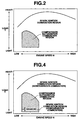
- FIG. 4 shows conditions for combustion changeover from the spark ignition combustion operation to the autoignition combustion operation.
- One is a combustion changeover in a light load region from the spark ignition combustion to the compression autoignition combustion or from the compression autoignition combustion to the spark ignition combustion.
- the other is a combustion changeover in a heavy load region from the compression autoignition combustion to the spark ignition combustion, or from the spark ignition combustion to the compression autoignition combustion.
- the present invention deals with the combustion changeover in the light load region.
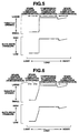
- FIG. 5 shows the throttle opening (degree) and in-cylinder pressure with respect to the load.
- the spark ignition combustion is a homogenous charge stoichiometric combustion.
- the throttle opening differs widely, and hence the in-cylinder pressure differs widely.
- the in-cylinder pressure can be deficient and the combustion can be unstable as mentioned before.
- FIG. 6 shows the throttle opening (degree) and in-cylinder pressure with respect to the load when a stratified charge spark ignition combustion is interposed.
- stratified charge combustion it is possible to make the air-fuel ratio lean while holding the air quantity at a large level. Therefore, the throttle opening can be increased, and the in-cylinder pressure can be held at a higher level as compared to the homogeneous charge stoichiometric combustion. In a combustion changeover, consequently, it is possible to bring the in-cylinder pressure quickly to a desired target value, and thereby to prevent the combustion from becoming unstable.
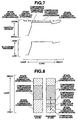
- FIG. 7 shows the throttle opening (degree) and in-cylinder pressure with respect to the load when a stratified charge combustion is performed in the compression autoignition mode.
- FIG. 8 shows combustion modes in combustion changeover.
- the engine performs stoichiometric homogeneous charge spark ignition combustion when the load is very light, and performs homogeneous charge compression autoignition combustion when the load is medium.
- homogeneous charge compression autoignition combustion when the load is medium.
- transient state operation with change in the load there appear, in the increasing order of the load, stoichiometric homogeneous charge spark ignition combustion, stratified charge spark ignition combustion, stratified charge compression autoignition combustion and homogeneous compression autoignition combustion, as shown in FIG. 8.
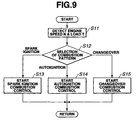
- FIG. 9 shows a main flow for controlling the combustion pattern.
- Step S11 is to detect engine speed N and load T.
- Step S12 is to select a combustion pattern from the map shown in FIG. 2.
- the spark ignition combustion control is started at step S13.
- the autoignition combustion control is started at step S14.
- Step S15 is to start a combustion changeover control when a combustion changeover is requested at step S12.
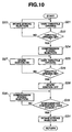
- FIG. 10 shows a control flow for changeover from the spark ignition combustion to the compression autoignition combustion.
- Step S21 is a step to vary the throttle opening.
- step S22 checks if the throttle opening is set to a desired target value shown in FIG. 7. If the setting of the throttle opening is not yet finished, step S23 continues intake stroke fuel injection to continue homogeneous charge spark ignition combustion. If the setting of the throttle opening is finished, control is transferred from step S22 to step S24 to perform compression stroke fuel injection to start stratified charge spark ignition combustion.
- Step S25 is to adjust the throttle opening again.
- Step S26 checks if the throttle opening is set to a desired value shown in FIG. 7. If the setting of the throttle opening is not yet finished, the spark ignition is continued to continue the spark ignition combustion at step S27. If the setting of the throttle opening is finished, the spark ignition is switched off at step S28 to initiate the compression autoignition combustion.
- Step S29 is to check if the engine load is within a homogeneous charge combustion load region shown in FIG. 8. If the engine load is outside the homogeneous charge combustion load region, step S30 performs the compression stroke fuel injection to perform the stratified charge compression autoignition combustion. If the engine load is inside the homogeneous charge combustion load region, step S31 performs the intake stroke fuel injection to initiate homogeneous charge compression autoignition combustion.
- FIG. 11 shows a control flow for combustion changeover from the compression autoignition combustion to the spark ignition combustion.
- first step S41 starts stratified charge compression autoignition combustion by the compression stroke fuel injection.
- step S42 is to adjust the throttle opening, and step S43 is to check if the throttle opening is set to a desired value as shown in FIG. 7. If the setting of the throttle opening is not yet finished, the compression autoignition combustion is continued at step S44 by holding the spark ignition off.
- step S45 If the setting of the throttle opening is finished, the spark ignition combustion is initiated at step S45 by turning on the spark ignition. Step S46 adjusts the throttle opening again, and step S47 checks again if the throttle opening is set to a desired value shown in FIG. 7. If the setting of the throttle opening is not yet finished, the stratified charge spark ignition combustion is continued by the compression stroke fuel injection at step S48. If the setting of the throttle opening is finished, homogeneous charge spark ignition combustion is initiated by the intake stroke fuel injection at step S49.
- FIG. 12 shows a compression autoignition gasoline engine according to a second embodiment of the present invention.
- the engine according to the second embodiment additionally has a variable valve timing system including variable timing valve actuating mechanisms 20 for the intake and exhaust valves 14 and 15.
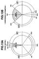
- FIG. 13A is a valve timing diagram for the spark ignition combustion mode
- FIG. 13B is a valve timing diagram for the compression autoignition combustion mode.
- the closing timing (EVC) of the exhaust valve (EXH) and the opening timing (IVO) of the intake valve (INT) are set around the piston top dead center to form a valve overlap as in an ordinary four cycle gasoline engine.
- the exhaust valve closing timing (EVC) is advanced, as compared to that in the spark ignition combustion mode, to close the exhaust valve on the exhaust stroke, and the intake valve opening timing (IVO) is retarded to open the intake valve during the intake stroke.
- the valve overlap around the piston top dead center is eliminated completely, and there is formed a minus overlap (-O/L) (or valve shutoff period).
- the exhaust valve is closed halfway during the exhaust stroke, so that high temperature burnt gases in the then-existing volume of the combustion chamber is trapped in the combustion chamber and brought over to the next cycle as internal EGR gas.
- the intake valve is opened during the intake stroke, and fresh air is inducted.
- the residual internal EGR gas gives heat to the inducted fresh air, and raises the in-cylinder temperature.
- FIG. 14 shows the throttle opening and in-cylinder pressure with respect to the load when the compression auto ignition combustion is performed in a light load region with fuel injection during the minus overlap.
- the compression autoignition combustion becomes possible at lighter load levels, and hence the combustion changeover can be realized at lighter load levels.
- an amount of fuel for combustion is decreased, and the tendency to knocking is decreased for both the spark ignition combustion and compression autoignition combustion. Because of the decrease in the amount of burnt fuel, the amount of heat generated in the combustion process becomes smaller, and the possibility of knock decreases even when the combustion parameters such as in-cylinder pressure and temperature deviate from desired values in the process of combustion changeover.
- FIG. 15 shows combustion modes in combustion changeover.
- the engine performs stoichiometric homogeneous charge spark ignition combustion when the load is very light, and performs homogeneous charge compression autoignition combustion when the load is medium.
- homogeneous charge compression autoignition combustion when the load is medium.
- transient state operation with change in the load there appear, in the increasing order of the load, stoichiometric homogeneous charge spark ignition combustion, stratified charge spark ignition combustion, minus overlap injection compression autoignition combustion and homogeneous charge compression autoignition combustion, as shown in FIG. 15.
- control flow for selecting a combustion patter in the second embodiment is identical to the flow shown in FIG. 9 in the first embodiment.
- FIG. 16 shows a control flow for changeover from the spark ignition combustion to the compression autoignition combustion.
- the control flow of FIG. 16 is different from the flow of FIG. 10 in the following points.
- Step S55 adjusts the throttle opening and the valve timings.
- Step S56 starts minus overlap fuel injection.
- Step S57 checks if the throttle opening and the valve timings are set to desired values (shown in FIGS. 13 and 14). If the setting is not yet complete, step S58 continues the spark ignition combustion. If the setting is complete, step S59 turns off the spark ignition, and starts the compression autoignition combustion.
- Step S60 checks whether the engine operating state is in a predetermined homogeneous charge combustion region on the basis of FIG. 15. Outside the homogeneous charge combustion region, step 61 continues the minus overlap fuel injection. Inside the homogeneous charge combustion region, step S62 starts the intake stroke fuel injection to start the homogeneous charge compression autoignition combustion.
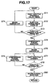
- FIG. 17 shows a control flow for combustion changeover from the compression autoignition combustion to the spark ignition combustion according to the second embodiment.
- the control flow of FIG. 17 is different from the flow of FIG. 11 in the following points.
- Step S71 adjusts the throttle opening and the valve timings.
- Step S72 starts the minus overlap fuel injection.
- Step S73 checks if the setting of the throttle opening and valve timings is finished. If the setting is not yet finished, step S74 continues the compression autoignition combustion by holding the spark ignition off. If the setting is finished, step S75 changes the fuel injection timing to start the compression stroke fuel injection.
- Step S76 following step S75 starts the spark ignition to start the stratified charge spark ignition combustion.
- FIG. 18 shows a compression autoignition gasoline engine according to a third embodiment of the present invention.
- a combustion chamber 201 is formed by a cylinder head 202, a cylinder block 203 and a piston 206.
- Cylinder head 2 has at least one intake port 204 provided with an intake valve 205, and at least one exhaust port 208 provided with an exhaust valve 209.
- Intake valve 205 and exhaust valve 209 are opened and closed through an intake cam 211 and an exhaust cam 212, respectively, by a valve actuating system.
- a variable valve timing control system includes valve timing control actuators 213 for varying the opening and closing timings of intake and exhaust valves 205 and 208 under the control of an engine control unit 214.
- Engine control unit 214 can achieve a high temperature high pressure state enabling spontaneous ignition near compression stroke top dead center by varying the compression ratio and the amount of EGR in a low and medium load region of the engine.
- An intake system includes a throttle valve (not shown in FIG. 18) for regulating an air quantity, and an air flowmeter (not shown).
- a fuel injector 207 is provided in cylinder head 202, to inject fuel directly into combustion chamber 201.
- Engine control unit 214 can control the fuel injection timing, the number of times of fuel injection, and the fuel injection quantity.
- a spark plug 210 is fixed to the cylinder head 202 by means of screw thread. Engine control unit 214 can control the spark ignition timing.
- FIGS. 19A and 19B illustrate opening and closing timings of the intake and exhaust valves according to this embodiment.
- the intake and exhaust valves are both open during a period called a valve overlap period from several degrees to several tens of degrees of crankshaft rotation around the exhaust top dead center (TDC).
- the valve shutoff period (or minus overlap period) during which the intake and exhaust valves are both closed is provided by decreasing the exhaust operating angle, shifting the exhaust valve closing timing (EVC) before the exhaust TDC, decreasing the intake operating angle and shifting the intake valve opening timing (IVO) after the exhaust TDC.
- EMC exhaust valve closing timing
- IVO intake valve opening timing
- this setting of the valve timing for the compression autoignition combustion is used also for the spark ignition combustion just before combustion changeover from the spark ignition combustion to the compression autoignition combustion.
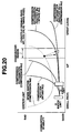
- FIG. 20 illustrates the combustion stability with respect to the air-fuel ratio (A/F) in the compression autoignition combustion and spark ignition combustion under the condition of constant throttle opening in the case in which the valve shutoff period is provided.
- A/F air-fuel ratio
- a stable combustion region can be expanded to the lean A/F side (to the low load side, that is).
- the fuel injected during the valve shutoff period is compressed together with self EGR gas mixture, exposed to a field of high temperature and high pressure, and reformed by reaction with oxygen in the self EGR gas mixture to the state making easier the compression autoignition.
- a broken line indicates a stable combustion region of stratified charge spark ignition combustion at the same valve shutoff period and the same throttle opening as the compression autoignition combustion. Even in a field of stratified air fuel mixture in which compression autoignition does not occur, it is possible to achieve flame propagation combustion in a predetermined A/F region, by producing a nucleus of flame by a spark.
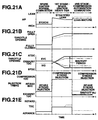
- FIGS. 21A ⁇ 21E show a process of combustion changeover according to the third embodiment of the present invention.
- the combustion changeover process is divided into first and second stages.
- a transition takes place from spark ignition combustion of homogeneous premixed mixture at the theoretical mixture ratio with fuel injection on the intake stroke, to spark ignition combustion of stratified lean mixture with greater throttle opening and fuel injection on the compression stroke.
- the intake and exhaust valve timings are varied to form the valve shutoff period.
- the valve shutoff period is made longer, the throttle opening is increased so as to compensate for a decrease in the fresh intake air quantity due to an increase of the self EGR gas quantity, to a position near the fully open throttle valve position.
- the state shown by a small black circle in FIG. 20 is reached.
- a transition from the spark ignition combustion to the compression autoignition combustion is carried out by changing the fuel injection timing from the compression stroke to the valve shutoff period to start a valve shutoff period fuel injection.
- the combustion state is shifted from the small black circle to a small white circle as shown by a solid line arrow in FIG. 20.
- the fuel injection quantity is decreased to absorb a load change in the combustion changeover. This is due to the effect of improvement in thermal efficiency in the compression autoignition combustion.
- the time period of combustion is short, and hence the thermal efficiency is improved, as compared to the spark ignition combustion. In this case, it is possible to stop the discharge at the spark plug simultaneously with the transition to the compression autoignition combustion.
- broken and one dot chain lines indicate characteristics when the load at the time of a combustion changeover is different from that in the above-mentioned base state.
- the broken lines show a case of lower load, and the one dot chain lines shows a case of higher load.
- the opening of the throttle valve to a degree required in the compression autoignition combustion becomes unfeasible.
- the transition is carried out by shifting the fuel injection timing to the valve shutoff period as in the base state.
- the compression autoignition combustion tends to be unstable until the intake pressure rises.
- the fuel is injected twice, at a first injection timing during the valve shutoff period and at a second injection timing during the compression stroke.
- the stability is thus improved by the effect of fuel reformation by the valve shutoff period fuel injection and the effect of stratification by the compression stroke fuel injection.
- This switching operation of the fuel injection timing can be expressed by a broken line arrow from the small black circle to a small white triangle shown in FIG. 20.
- the control system can increase the temperature of the self EGR gas, and increase an amount of HC residing in the self EGR gas mixture, so that the compression autoignition combustion is reliably initiated immediately after the combustion changeover.
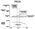
- FIG. 22 shows the fuel injection timing, and the valve shutoff period in combustion changeover processes in the base state, the low load state and the high load state, as explained above.
- the fuel injection may be performed twice, a first fuel injection of a first amount of fuel during the valve shutoff period and a second fuel injection of a second amount of fuel during a period from the valve shutoff period to an power stroke.
- the second fuel injection may be performed on the compression stroke when the load is lower and on the intake stroke when the load is higher.
- the control system can perform the fuel reformation during the compression stroke adequately and start the compression autoignition combustion stably.
- the valve shutoff period is held at a constant length in a low load region to ensure the fuel reformation, and decreased with increase in the load in a high load region to prevent over fuel reformation and thereby to prevent knocking.
- a combustion changeover from the spark ignition combustion to the compression autoignition combustion is achieved by changing the fuel injection timing of the fuel injector for each cylinder. Therefore, it is easy to vary the timing of a combustion changeover from cylinder to cylinder. It is possible to decrease the engine torque change in a combustion changeover from the spark ignition combustion to the compression autoignition combustion by performing a changeover of the fuel injection timing sequentially cylinder by cylinder, or one cylinder group after another.
- the amount of the fuel injected during the valve shutoff period may be increased as compared to an amount of fuel injected in normal compression autoignition combustion, to promote the fuel reformation and further improve the combustion stability at a start of the compression autoignition combustion.
- the stratified charge spark ignition combustion in changeover from the spark ignition combustion to the compression autoignition combustion is effective for increasing the in-cylinder pressure in the combustion changeover, and thereby improving the stability of the compression autoignition combustion.
- the stratified charge spark ignition combustion in changeover from the compression autoignition combustion to the spark ignition combustion is effective for restraining an, increase in the fuel quantity as compared to homogeneous charge spark ignition combustion, and preventing knock in the spark ignition combustion.
- the stratified charge compression autoignition combustion in changeover from the spark ignition combustion to the compression autoignition combustion is effective for improving the ignitability in the compression autoignition combustion, and improving the stability of the compression autoignition combustion.
- the stratified charge compression autoignition combustion in changeover from the compression autoignition combustion to the spark ignition combustion is effective for lowering the load at the time of the compression autoignition combustion, reducing the fuel injection quantity in the spark ignition combustion after the combustion changeover, and preventing knock.
- the valve shutoff period fuel injection in changeover from the spark ignition combustion to the compression autoignition combustion is effective for performing the combustion changeover from the spark ignition combustion to the compression autoignition promptly and reliably within one combustion cycle even if the response of the system for controlling the valve timings is slow.
- the valve shutoff period fuel injection in changeover from the compression autoignition combustion to the spark ignition combustion is effective for lowering the load at the time of the compression autoignition combustion, decreasing the fuel injection quantity in the spark ignition combustion after the changeover and thereby preventing knock.
Landscapes
- Engineering & Computer Science (AREA)
- Chemical & Material Sciences (AREA)
- Combustion & Propulsion (AREA)
- Mechanical Engineering (AREA)
- General Engineering & Computer Science (AREA)
- Output Control And Ontrol Of Special Type Engine (AREA)
- Electrical Control Of Air Or Fuel Supplied To Internal-Combustion Engine (AREA)
- Electrical Control Of Ignition Timing (AREA)
- Combustion Methods Of Internal-Combustion Engines (AREA)
- Exhaust-Gas Circulating Devices (AREA)
- Combined Controls Of Internal Combustion Engines (AREA)
Applications Claiming Priority (4)
| Application Number | Priority Date | Filing Date | Title |
|---|---|---|---|
| JP26100299 | 1999-09-14 | ||
| JP26100299 | 1999-09-14 | ||
| JP2000270170 | 2000-09-06 | ||
| JP2000270170A JP4253426B2 (ja) | 1999-09-14 | 2000-09-06 | 圧縮自己着火式ガソリン機関 |
Publications (3)
| Publication Number | Publication Date |
|---|---|
| EP1085192A2 true EP1085192A2 (fr) | 2001-03-21 |
| EP1085192A3 EP1085192A3 (fr) | 2003-07-02 |
| EP1085192B1 EP1085192B1 (fr) | 2004-09-01 |
Family
ID=26544857
Family Applications (1)
| Application Number | Title | Priority Date | Filing Date |
|---|---|---|---|
| EP00119934A Expired - Lifetime EP1085192B1 (fr) | 1999-09-14 | 2000-09-13 | Moteur à combustion à pétrole avec allumage par compression |
Country Status (4)
| Country | Link |
|---|---|
| US (1) | US6336436B1 (fr) |
| EP (1) | EP1085192B1 (fr) |
| JP (1) | JP4253426B2 (fr) |
| DE (1) | DE60013379T2 (fr) |
Cited By (27)
| Publication number | Priority date | Publication date | Assignee | Title |
|---|---|---|---|---|
| EP1108868A3 (fr) * | 1999-12-14 | 2002-01-23 | Nissan Motor Co., Ltd. | Moteur à compression de mélange et à allumage par compression |
| FR2835880A1 (fr) * | 2002-02-12 | 2003-08-15 | Peugeot Citroen Automobiles Sa | Moteur a injection perfectionnee |
| US6640771B2 (en) | 2001-09-25 | 2003-11-04 | Avl List Gmbh | Internal combustion engine |
| FR2840015A1 (fr) * | 2002-05-23 | 2003-11-28 | Renault Sa | Procede de controle de la combustion d'un moteur a combustion interne de type a allumage par compression et dispositif de commande pour la mise en oeuvre d'un tel procede |
| US6742494B2 (en) | 2001-08-27 | 2004-06-01 | Avl List Gmbh | Method of operating an internal combustion engine |
| US6752123B2 (en) | 2001-09-06 | 2004-06-22 | Avl List Gmbh | Method for operating an internal combustion engine |
| FR2853358A1 (fr) * | 2003-04-04 | 2004-10-08 | Peugeot Citroen Automobiles Sa | Moteur a combustion interne a essence et a auto-allumage |
| US6840237B2 (en) | 2002-12-30 | 2005-01-11 | Ford Global Technologies, Llc | Method for auto-ignition operation and computer readable storage device |
| EP1496231A1 (fr) * | 2003-07-01 | 2005-01-12 | Ford Global Technologies, LLC | Méthode, dispositif et support de stockage lisible par ordinateur pour commander la combustion par auto-allumage d'un mélange homogène |
| WO2005059340A1 (fr) * | 2003-12-17 | 2005-06-30 | Daimlerchrysler Ag | Procede pour faire fonctionner un moteur a combustion interne pendant une phase de changement de fonctionnement |
| DE102004019300A1 (de) * | 2004-04-21 | 2005-11-10 | Volkswagen Ag | Verfahren zur Motorsteuerung und entsprechende Motorsteuerung |
| EP1705358A1 (fr) * | 2005-03-22 | 2006-09-27 | Ford Global Technologies, LLC | Moteur à combustion interne et méthode de commande de commutation de mode |
| DE102005031241A1 (de) * | 2005-07-01 | 2007-01-04 | Fev Motorentechnik Gmbh | Variabler Ventiltrieb einer Kolben-Brennkraftmaschine |
| WO2007042386A1 (fr) * | 2005-10-10 | 2007-04-19 | Robert Bosch Gmbh | Procede pour faire fonctionner un moteur a combustion interne |
| WO2007048661A1 (fr) * | 2005-10-25 | 2007-05-03 | Robert Bosch Gmbh | Procede de commande d'un moteur a combustion interne |
| WO2008059981A1 (fr) * | 2006-11-14 | 2008-05-22 | Kabushiki Kaisha Toyota Jidoshokki | Moteur hcci |
| US7387104B2 (en) | 2003-04-04 | 2008-06-17 | Peugeot Citroen Automobiles Sa | Internal combustion engine with direct gasoline injection and controlled ignition |
| EP1953375A1 (fr) * | 2007-01-30 | 2008-08-06 | Mazda Motor Corporation | Procédé et produit de programme informatique pour le fonctionnement d'un moteur à combustion interne ainsi qu'un système de fonctionnement de moteur |
| WO2009024170A1 (fr) * | 2007-08-22 | 2009-02-26 | Fev Motorentechnik Gmbh | Moteur à combustion interne et mécanisme de soupapes variable commandé par came |
| WO2009109540A3 (fr) * | 2008-03-05 | 2010-04-22 | Continental Automotive Gmbh | Procédé de transfert à émissions réduites d'un mode de fonctionnement d'un moteur à combustion interne à un autre |
| US7805237B2 (en) | 2006-11-08 | 2010-09-28 | Iav Gmbh Ingenieurgesellschaft Auto Und Verkehr | Method for operating an internal combustion engine |
| EP1757787A4 (fr) * | 2004-01-20 | 2011-12-07 | Honda Motor Co Ltd | Procede de commande et dispositif de commande pour moteur a combustion interne |
| DE102010050853A1 (de) | 2010-11-09 | 2012-05-10 | GPI Ges. f. Prüfstanduntersuchungen und Ingenieurdienstleistungen mbH | Verfahren und Vorrichtung zum Betrieb eines Kraftstoffsystems |
| CN104603425A (zh) * | 2012-09-07 | 2015-05-06 | 马自达汽车株式会社 | 火花点火式发动机 |
| DE10350798B4 (de) * | 2003-10-29 | 2016-03-24 | Daimler Ag | Verfahren zum Betrieb einer Brennkraftmaschine |
| EP2843208A4 (fr) * | 2012-04-23 | 2016-03-30 | Beijing Endeavour Technology Co Ltd | Procédé de commande de combustion hybride de moteur à combustion interne et dispositif de commande associé, moteur à combustion interne et automobile |
| EP2971713B1 (fr) * | 2013-02-21 | 2020-11-04 | Robert Bosch GmbH | Système et procédé pour commander une transition entre les modes de combustion si et hcci |
Families Citing this family (131)
| Publication number | Priority date | Publication date | Assignee | Title |
|---|---|---|---|---|
| DE60015885T2 (de) | 1999-09-17 | 2005-03-17 | Nissan Motor Co., Ltd., Yokohama | Benzinbrennkraftmaschine mit Verdichtungszündung |
| JP4016568B2 (ja) * | 2000-03-30 | 2007-12-05 | 日産自動車株式会社 | ガソリン自己着火式内燃機関 |
| DE10122775A1 (de) * | 2000-05-18 | 2001-11-22 | Ford Global Tech Inc | Hybrider Motor und Verfahren zu dessen Taktsteuerung |
| EP1310649B1 (fr) * | 2000-08-17 | 2016-11-23 | Hitachi, Ltd. | Moteur a combustion interne par compression |
| JP4517515B2 (ja) * | 2001-02-14 | 2010-08-04 | マツダ株式会社 | 自動車用4サイクルエンジン |
| WO2002097255A1 (fr) * | 2001-05-22 | 2002-12-05 | Hitachi, Ltd. | Moteur thermique a allumage par compression |
| JP3885524B2 (ja) * | 2001-06-25 | 2007-02-21 | 日産自動車株式会社 | 圧縮自己着火内燃機関 |
| JP3975695B2 (ja) * | 2001-06-25 | 2007-09-12 | 日産自動車株式会社 | 自己着火式エンジン |
| WO2003064838A1 (fr) | 2002-01-31 | 2003-08-07 | Mazda Motor Corporation | Dispositif de commande d'un moteur a etincelles |
| US7182050B2 (en) | 2002-01-31 | 2007-02-27 | Mazda Motor Corporation | Control device for spark-ignition engine |
| JP2004225680A (ja) * | 2002-11-28 | 2004-08-12 | Toyota Industries Corp | 内燃機関及び内燃機関用制御装置 |
| US6851408B2 (en) * | 2002-12-25 | 2005-02-08 | Nissan Motor Co., Ltd. | Direct fuel injection engine |
| US7093568B2 (en) * | 2003-01-13 | 2006-08-22 | Ford Global Technologies, Llc | Control of autoignition timing in a HCCI engine |
| JP4066851B2 (ja) | 2003-03-03 | 2008-03-26 | トヨタ自動車株式会社 | 可変サイクルエンジンおよび運転モードの切り替え方法 |
| US6968825B2 (en) * | 2003-06-06 | 2005-11-29 | Mazda Motor Corporation | Control device for spark-ignition engine |
| US7004124B2 (en) * | 2003-07-01 | 2006-02-28 | General Motors Corporation | Valve strategy for operating a controlled auto-ignition four-stroke internal combustion engine |
| DE10344428B4 (de) * | 2003-09-25 | 2015-02-19 | Daimler Ag | Verfahren zum Betrieb einer Brennkraftmaschine |
| DE10348138B4 (de) * | 2003-10-16 | 2016-09-15 | Daimler Ag | Verfahren zum Betrieb einer Brennkraftmaschine |
| DE10348139A1 (de) * | 2003-10-16 | 2005-05-12 | Daimler Chrysler Ag | Verfahren zum Betrieb einer Brennkraftmaschine |
| DE10350797B4 (de) * | 2003-10-29 | 2014-02-06 | Daimler Ag | Verfahren zum Betrieb einer Brennkraftmaschine |
| DE10350796A1 (de) * | 2003-10-29 | 2005-05-25 | Daimlerchrysler Ag | Verfahren zum Betrieb einer Brennkraftmaschine |
| US6968830B2 (en) * | 2003-12-30 | 2005-11-29 | General Electric Company | Apparatus and method for suppressing internal combustion ignition engine emissions |
| US7107946B2 (en) * | 2004-03-19 | 2006-09-19 | Ford Global Technologies, Llc | Electromechanically actuated valve control for an internal combustion engine |
| US7194993B2 (en) * | 2004-03-19 | 2007-03-27 | Ford Global Technologies, Llc | Starting an engine with valves that may be deactivated |
| US7383820B2 (en) | 2004-03-19 | 2008-06-10 | Ford Global Technologies, Llc | Electromechanical valve timing during a start |
| US7021289B2 (en) * | 2004-03-19 | 2006-04-04 | Ford Global Technology, Llc | Reducing engine emissions on an engine with electromechanical valves |
| US7031821B2 (en) * | 2004-03-19 | 2006-04-18 | Ford Global Technologies, Llc | Electromagnetic valve control in an internal combustion engine with an asymmetric exhaust system design |
| US7072758B2 (en) * | 2004-03-19 | 2006-07-04 | Ford Global Technologies, Llc | Method of torque control for an engine with valves that may be deactivated |
| US7032581B2 (en) * | 2004-03-19 | 2006-04-25 | Ford Global Technologies, Llc | Engine air-fuel control for an engine with valves that may be deactivated |
| US7128043B2 (en) | 2004-03-19 | 2006-10-31 | Ford Global Technologies, Llc | Electromechanically actuated valve control based on a vehicle electrical system |
| US7140355B2 (en) * | 2004-03-19 | 2006-11-28 | Ford Global Technologies, Llc | Valve control to reduce modal frequencies that may cause vibration |
| US7063062B2 (en) * | 2004-03-19 | 2006-06-20 | Ford Global Technologies, Llc | Valve selection for an engine operating in a multi-stroke cylinder mode |
| US7165391B2 (en) | 2004-03-19 | 2007-01-23 | Ford Global Technologies, Llc | Method to reduce engine emissions for an engine capable of multi-stroke operation and having a catalyst |
| US7107947B2 (en) * | 2004-03-19 | 2006-09-19 | Ford Global Technologies, Llc | Multi-stroke cylinder operation in an internal combustion engine |
| US7066121B2 (en) * | 2004-03-19 | 2006-06-27 | Ford Global Technologies, Llc | Cylinder and valve mode control for an engine with valves that may be deactivated |
| US7079935B2 (en) * | 2004-03-19 | 2006-07-18 | Ford Global Technologies, Llc | Valve control for an engine with electromechanically actuated valves |
| US7240663B2 (en) * | 2004-03-19 | 2007-07-10 | Ford Global Technologies, Llc | Internal combustion engine shut-down for engine having adjustable valves |
| US7555896B2 (en) | 2004-03-19 | 2009-07-07 | Ford Global Technologies, Llc | Cylinder deactivation for an internal combustion engine |
| US7559309B2 (en) | 2004-03-19 | 2009-07-14 | Ford Global Technologies, Llc | Method to start electromechanical valves on an internal combustion engine |
| US7128687B2 (en) * | 2004-03-19 | 2006-10-31 | Ford Global Technologies, Llc | Electromechanically actuated valve control for an internal combustion engine |
| DE102004034505B4 (de) * | 2004-07-16 | 2018-01-04 | Daimler Ag | Verfahren zum Betrieb einer Brennkraftmaschine |
| US7152559B2 (en) * | 2004-07-26 | 2006-12-26 | General Motors Corporation | Valve and fueling strategy for operating a controlled auto-ignition four-stroke internal combustion engine |
| US7128047B2 (en) * | 2004-07-26 | 2006-10-31 | General Motors Corporation | Valve and fueling strategy for operating a controlled auto-ignition four-stroke internal combustion engine |
| US7150250B2 (en) * | 2004-07-26 | 2006-12-19 | General Motors Corporation | Valve and fueling strategy for operating a controlled auto-ignition four-stroke internal combustion engine |
| US7021277B2 (en) * | 2004-07-26 | 2006-04-04 | General Motors Corporation | Valve and fueling strategy for operating a controlled auto-ignition four-stroke internal combustion engine |
| DE112006000529B4 (de) * | 2005-03-03 | 2016-02-18 | General Motors Global Technology Operations, Inc. | Verfahren zur Steuerung transienter Lasten zwischen mageren und stöchiometrischen Verbrennungsbetriebsarten von Direkteinspritzmaschinen mit gesteuerter Selbstzündungsverbrennung |
| CN101287897A (zh) * | 2005-03-03 | 2008-10-15 | 通用汽车环球科技运作公司 | 用于具有受控自动点火燃烧的直接喷射发动机的负荷瞬态控制方法 |
| WO2006096425A2 (fr) * | 2005-03-03 | 2006-09-14 | General Motors Global Technology Operations, Inc. | Procede de transition entre un mode d'auto-allumage controle et un mode d'allumage commande d'un moteur a injection directe |
| WO2006096423A2 (fr) * | 2005-03-03 | 2006-09-14 | General Motors Global Technology Operations, Inc. | Procedes de commande transitoire de vitesse pour moteurs a injection directe a combustion en auto-allumage controle |
| JP4365812B2 (ja) | 2005-09-15 | 2009-11-18 | 株式会社日立製作所 | 内燃機関の制御装置及び制御方法 |
| US7240659B2 (en) * | 2005-09-21 | 2007-07-10 | Ford Global Technologies, Llc | Transition strategy for engine operation with spark ignition and homogeneous charge compression ignition modes |
| US7234438B2 (en) * | 2005-09-21 | 2007-06-26 | Ford Global Technologies, Llc | System and method for engine operation with spark assisted compression ignition |
| US7168420B1 (en) | 2005-09-21 | 2007-01-30 | Ford Global Technologies, Llc | System and method for engine operation with spark assisted compression ignition |
| US7287521B2 (en) * | 2005-09-21 | 2007-10-30 | Ford Global Technologies Llc | System and method for improved engine starting using heated intake air |
| US7213585B2 (en) * | 2005-09-21 | 2007-05-08 | Ford Global Technologies, Llc | System and method for maintaining heated intake air |
| US7213572B2 (en) * | 2005-09-21 | 2007-05-08 | Ford Global Technologies, Llc | System and method for engine operation with spark assisted compression ignition |
| JP4591300B2 (ja) * | 2005-09-29 | 2010-12-01 | マツダ株式会社 | 4サイクル火花点火式エンジン |
| US7363911B2 (en) * | 2005-11-03 | 2008-04-29 | Ford Global Technologies, Llc | Humidity-based combustion control in a multiple combustion mode engine |
| US7503167B2 (en) * | 2005-11-18 | 2009-03-17 | Ford Global Technologies, Llc | Internal combustion engine with multiple combustion modes and fuel vapor purging |
| US7503166B2 (en) * | 2005-11-18 | 2009-03-17 | Ford Global Technologies, Llc | Gasoline internal combustion engine with dynamic combustion mode allocation |
| US7552588B2 (en) * | 2005-12-15 | 2009-06-30 | Ford Global Technologies, Llc | System and method for HCCI temperature control |
| US7347178B2 (en) * | 2006-01-12 | 2008-03-25 | Ford Global Technologies, Llc | System and method for controlling auto-ignition |
| JP2007224908A (ja) * | 2006-02-20 | 2007-09-06 | Robert Bosch Gmbh | 内燃機関の運転方法 |
| US7469672B2 (en) * | 2006-03-06 | 2008-12-30 | Ford Global Technologies, Llc | System and method for operation of an engine having multiple combustion modes and cylinder deactivation |
| US7497198B2 (en) * | 2006-03-06 | 2009-03-03 | Ford Global Technologies, Llc | System and method for controlling vehicle operation in response to fuel vapor purging |
| US7694760B2 (en) * | 2006-03-06 | 2010-04-13 | Ford Global Technologies, Llc | System and method for controlling vehicle operation |
| US7487852B2 (en) * | 2006-03-06 | 2009-02-10 | Ford Global Technologies, Llc | System and method for controlling vehicle operation |
| JP2007255329A (ja) | 2006-03-23 | 2007-10-04 | Honda Motor Co Ltd | 内燃機関システム |
| DE102006027571A1 (de) * | 2006-06-14 | 2007-12-20 | Robert Bosch Gmbh | Verfahren zum Betrieb einer Brennkraftmaschine |
| JP4466616B2 (ja) * | 2006-06-19 | 2010-05-26 | トヨタ自動車株式会社 | 多種燃料内燃機関 |
| US7246595B1 (en) * | 2006-06-28 | 2007-07-24 | Ford Global Technologies, Llc | Diesel engine with differential cylinder group operation |
| DE102006033024A1 (de) * | 2006-07-17 | 2008-01-24 | Robert Bosch Gmbh | Verfahren zum Betrieb einer Brennkraftmaschine |
| US7213566B1 (en) | 2006-08-10 | 2007-05-08 | Ford Global Technologies, Llc | Engine system and method of control |
| US7448359B2 (en) * | 2006-08-10 | 2008-11-11 | Ford Global Technologies, Llc | Multi-mode internal combustion engine |
| JP4649383B2 (ja) * | 2006-08-21 | 2011-03-09 | 本田技研工業株式会社 | 内燃機関の制御装置 |
| US7748355B2 (en) * | 2006-09-15 | 2010-07-06 | Ford Global Technologies, Llc | Approach for facilitating engine mode transitions |
| BRPI0703981A2 (pt) | 2006-10-30 | 2009-06-23 | Honda Motor Co Ltd | sistema de motor de combustão interna |
| US7832370B2 (en) * | 2006-11-16 | 2010-11-16 | Gm Global Technology Operations, Inc. | Low-load operation extension of a homogeneous charge compression ignition engine |
| DE602006011483D1 (de) * | 2006-11-22 | 2010-02-11 | Ford Global Tech Llc | HCCI-Brennkraftmaschine mit Schnellneustart |
| JP4715753B2 (ja) * | 2007-01-09 | 2011-07-06 | トヨタ自動車株式会社 | 内燃機関 |
| JP4737103B2 (ja) * | 2007-01-30 | 2011-07-27 | マツダ株式会社 | ガソリンエンジンの制御装置 |
| US8195375B2 (en) * | 2007-08-17 | 2012-06-05 | GM Global Technology Operations LLC | Method for controlling combustion mode transitions in an internal combustion engine |
| JP2008019873A (ja) * | 2007-10-04 | 2008-01-31 | Toyota Motor Corp | 圧縮比変更期間における内燃機関の制御 |
| JP4858397B2 (ja) * | 2007-10-15 | 2012-01-18 | 株式会社豊田自動織機 | 予混合圧縮着火機関 |
| WO2009102744A1 (fr) * | 2008-02-15 | 2009-08-20 | Gm Global Technology Operations, Inc. | Procédé de commande d'un moteur à combustion interne à injection directe et à allumage commandé à des charges faibles |
| DE112009000572B4 (de) * | 2008-03-11 | 2017-10-05 | GM Global Technology Operations LLC (n. d. Ges. d. Staates Delaware) | Steuerverfahren für Übergänge eines Verbrennungsmotors zwischen einem Verbrennungsmodus mit homogener Kompressionszündung und einem Verbrennungsmodus mit Funkenzündung |
| US8220436B2 (en) * | 2008-03-13 | 2012-07-17 | GM Global Technology Operations LLC | HCCI/SI combustion switching control system and method |
| JP4957674B2 (ja) * | 2008-07-24 | 2012-06-20 | 株式会社デンソー | 内燃機関の制御装置及び制御システム |
| JP5087569B2 (ja) * | 2009-02-23 | 2012-12-05 | 日立オートモティブシステムズ株式会社 | 圧縮自己着火式内燃機関の制御装置 |
| US8316818B2 (en) * | 2009-04-28 | 2012-11-27 | GM Global Technology Operations LLC | HCCI mode switching control system and method |
| JP4748255B2 (ja) * | 2009-06-03 | 2011-08-17 | マツダ株式会社 | エンジンの制御方法および制御装置 |
| US8776762B2 (en) * | 2009-12-09 | 2014-07-15 | GM Global Technology Operations LLC | HCCI mode switching control system and method |
| US8955492B2 (en) * | 2010-05-24 | 2015-02-17 | GM Global Technology Operations LLC | Control strategy for transitions between homogeneous-charge compression-ignition and spark-ignition combustion modes |
| JP2012002088A (ja) * | 2010-06-15 | 2012-01-05 | Nippon Soken Inc | 内燃機関の制御装置 |
| JP5447408B2 (ja) * | 2011-02-24 | 2014-03-19 | マツダ株式会社 | 火花点火式ガソリンエンジンの制御装置 |
| US9151240B2 (en) | 2011-04-11 | 2015-10-06 | GM Global Technology Operations LLC | Control system and method for a homogeneous charge compression ignition (HCCI) engine |
| US9074551B2 (en) * | 2011-07-13 | 2015-07-07 | GM Global Technology Operations LLC | Method and apparatus for engine operation in homogeneous charge compression ignition and spark ignition |
| US9429096B2 (en) * | 2011-09-15 | 2016-08-30 | Robert Bosch Gmbh | Predictive modeling and reducing cyclic variability in autoignition engines |
| DE102011083946A1 (de) * | 2011-10-04 | 2013-04-04 | Robert Bosch Gmbh | Verfahren zum Betreiben einer Brennkraftmaschine |
| JP5756400B2 (ja) * | 2011-12-27 | 2015-07-29 | 本田技研工業株式会社 | 圧縮着火内燃機関の制御装置 |
| JP5915472B2 (ja) * | 2012-09-07 | 2016-05-11 | マツダ株式会社 | 火花点火式直噴エンジン |
| JP6002521B2 (ja) * | 2012-09-27 | 2016-10-05 | 日立オートモティブシステムズ株式会社 | 筒内噴射エンジンの制御装置 |
| EP2976515B1 (fr) * | 2013-02-21 | 2019-12-04 | Robert Bosch GmbH | Système et procédé de commande d'une transition entre des modes de combustion si et hcci |
| JP5870951B2 (ja) * | 2013-03-25 | 2016-03-01 | マツダ株式会社 | 火花点火式エンジンの制御装置 |
| JP5994700B2 (ja) * | 2013-03-25 | 2016-09-21 | マツダ株式会社 | 火花点火式エンジンの制御装置 |
| JP6320882B2 (ja) * | 2014-09-11 | 2018-05-09 | 日立オートモティブシステムズ株式会社 | 内燃機関の可変燃焼システム |
| US20190226419A1 (en) * | 2014-10-23 | 2019-07-25 | Xiangjin Zhou | Hybrid combustion mode of internal combustion engine and controller thereof, internal combustion engine, and automobile |
| JP6191837B2 (ja) * | 2015-02-19 | 2017-09-06 | マツダ株式会社 | エンジンの制御装置 |
| US10415488B2 (en) | 2015-12-09 | 2019-09-17 | Hyundai Motor Company | System and method for controlling valve timing of continuous variable valve duration engine |
| US10393037B2 (en) | 2015-12-09 | 2019-08-27 | Hyundai Motor Company | Method for controlling of valve timing of continuous variable valve duration engine |
| KR101807034B1 (ko) | 2015-12-09 | 2017-12-08 | 현대자동차 주식회사 | 연속 가변 밸브 듀레이션 엔진의 밸브 타이밍 제어 시스템 및 방법 |
| KR102394575B1 (ko) | 2017-11-20 | 2022-05-04 | 현대자동차 주식회사 | 연속 가변 밸브 듀레이션 장치 및 이를 포함하는 엔진 |
| KR101807030B1 (ko) | 2015-12-09 | 2017-12-08 | 현대자동차 주식회사 | 연속 가변 밸브 듀레이션 엔진의 밸브 타이밍 제어 시스템 및 방법 |
| US10415485B2 (en) | 2015-12-10 | 2019-09-17 | Hyundai Motor Company | Method for controlling of valve timing of continuous variable valve duration engine |
| KR101807031B1 (ko) | 2015-12-10 | 2017-12-08 | 현대자동차 주식회사 | 연속 가변 밸브 듀레이션 엔진의 밸브 타이밍 제어 시스템 및 방법 |
| US10323585B2 (en) | 2015-12-11 | 2019-06-18 | Hyundai Motor Company | Method for controlling of valve timing of continuous variable valve duration engine |
| KR101807023B1 (ko) * | 2015-12-11 | 2017-12-08 | 현대자동차 주식회사 | 연속 가변 밸브 듀레이션 엔진의 밸브 타이밍 제어 시스템 및 방법 |
| KR101776743B1 (ko) | 2015-12-11 | 2017-09-08 | 현대자동차 주식회사 | 연속 가변 밸브 듀레이션 엔진의 밸브 타이밍 제어 시스템 및 방법 |
| US10428747B2 (en) | 2015-12-11 | 2019-10-01 | Hyundai Motor Company | System and method for controlling valve timing of continuous variable valve duration engine |
| US10920679B2 (en) | 2015-12-11 | 2021-02-16 | Hyundai Motor Company | Method for controlling of valve timing of continuous variable valve duration engine |
| US10634067B2 (en) | 2015-12-11 | 2020-04-28 | Hyundai Motor Company | System and method for controlling valve timing of continuous variable valve duration engine |
| KR101807037B1 (ko) | 2016-03-16 | 2017-12-08 | 현대자동차 주식회사 | 연속 가변 밸브 듀레이션 엔진의 밸브 타이밍 제어 시스템 및 방법 |
| US10634066B2 (en) | 2016-03-16 | 2020-04-28 | Hyundai Motor Company | System and method for controlling valve timing of continuous variable valve duration engine |
| WO2018096584A1 (fr) * | 2016-11-22 | 2018-05-31 | マツダ株式会社 | Dispositif de commande de moteur de type à auto-allumage par compression |
| WO2018096590A1 (fr) * | 2016-11-22 | 2018-05-31 | マツダ株式会社 | Dispositif de commande pour moteur de type à auto-allumage par compression |
| JP6848412B2 (ja) * | 2016-12-15 | 2021-03-24 | スズキ株式会社 | 内燃機関の制御装置 |
| WO2018216154A1 (fr) * | 2017-05-24 | 2018-11-29 | 日産自動車株式会社 | Procédé et dispositif de commande de moteur à combustion interne |
| JP6835216B2 (ja) * | 2017-05-24 | 2021-02-24 | 日産自動車株式会社 | 内燃機関の制御方法及び制御装置 |
| US10895208B2 (en) * | 2017-08-24 | 2021-01-19 | Mazda Motor Corporation | Control system for compression-ignition engine |
| JP6642559B2 (ja) * | 2017-12-15 | 2020-02-05 | マツダ株式会社 | 圧縮着火式エンジンの制御装置 |
| JP6558431B2 (ja) * | 2017-12-15 | 2019-08-14 | マツダ株式会社 | 圧縮着火式エンジンの制御装置 |
Family Cites Families (8)
| Publication number | Priority date | Publication date | Assignee | Title |
|---|---|---|---|---|
| JPS55137305A (en) | 1979-04-13 | 1980-10-27 | Nissan Motor Co Ltd | Valve lift for internal combustion engine |
| JP3435955B2 (ja) | 1996-01-29 | 2003-08-11 | 日産自動車株式会社 | 内燃機関の可変動弁機構の切換装置 |
| JP3629879B2 (ja) | 1997-03-13 | 2005-03-16 | トヨタ自動車株式会社 | 圧縮点火式内燃機関 |
| GB2327980A (en) * | 1997-08-01 | 1999-02-10 | Ford Global Tech Inc | Gasoline i.c. engine with spark-ignition and auto-ignition in the same cylinder |
| US6227151B1 (en) * | 1997-08-01 | 2001-05-08 | Ford Global Technologies, Inc. | Gasoline internal combustion engine |
| FR2768180B1 (fr) * | 1997-09-09 | 1999-10-08 | Inst Francais Du Petrole | Procede de fonctionnement d'un moteur 4 temps, en auto-allumage controle |
| JP3724542B2 (ja) * | 1998-11-18 | 2005-12-07 | 日産自動車株式会社 | 可変動弁エンジンの吸入空気量制御装置 |
| EP1052391B1 (fr) * | 1999-05-12 | 2004-04-28 | Nissan Motor Co., Ltd. | Moteur à auto-allumage |
-
2000
- 2000-09-06 JP JP2000270170A patent/JP4253426B2/ja not_active Expired - Lifetime
- 2000-09-13 EP EP00119934A patent/EP1085192B1/fr not_active Expired - Lifetime
- 2000-09-13 DE DE60013379T patent/DE60013379T2/de not_active Expired - Lifetime
- 2000-09-13 US US09/661,407 patent/US6336436B1/en not_active Expired - Lifetime
Cited By (39)
| Publication number | Priority date | Publication date | Assignee | Title |
|---|---|---|---|---|
| US6390057B2 (en) | 1999-12-14 | 2002-05-21 | Nissan Motor Co., Ltd. | Compression self-ignition gasoline engine |
| EP1108868A3 (fr) * | 1999-12-14 | 2002-01-23 | Nissan Motor Co., Ltd. | Moteur à compression de mélange et à allumage par compression |
| US6742494B2 (en) | 2001-08-27 | 2004-06-01 | Avl List Gmbh | Method of operating an internal combustion engine |
| US6752123B2 (en) | 2001-09-06 | 2004-06-22 | Avl List Gmbh | Method for operating an internal combustion engine |
| DE10237496B4 (de) * | 2001-09-06 | 2006-08-31 | Avl List Gmbh | Verfahren zum Betrieb einer Brennkraftmaschine |
| US6640771B2 (en) | 2001-09-25 | 2003-11-04 | Avl List Gmbh | Internal combustion engine |
| FR2835880A1 (fr) * | 2002-02-12 | 2003-08-15 | Peugeot Citroen Automobiles Sa | Moteur a injection perfectionnee |
| FR2840015A1 (fr) * | 2002-05-23 | 2003-11-28 | Renault Sa | Procede de controle de la combustion d'un moteur a combustion interne de type a allumage par compression et dispositif de commande pour la mise en oeuvre d'un tel procede |
| US6840237B2 (en) | 2002-12-30 | 2005-01-11 | Ford Global Technologies, Llc | Method for auto-ignition operation and computer readable storage device |
| US7059296B2 (en) | 2002-12-30 | 2006-06-13 | Ford Global Technologies, Llc | Method for auto-ignition operation and computer readable storage device |
| US7400966B2 (en) | 2002-12-30 | 2008-07-15 | Ford Global Technologies, Llc | Method for auto-ignition operation and computer readable storage device for use with an internal combustion engine |
| US7441538B2 (en) | 2002-12-30 | 2008-10-28 | Ford Global Technologies, Llc | Method for auto-ignition operation and computer storage device for use with an internal combustion engine |
| US7387104B2 (en) | 2003-04-04 | 2008-06-17 | Peugeot Citroen Automobiles Sa | Internal combustion engine with direct gasoline injection and controlled ignition |
| FR2853358A1 (fr) * | 2003-04-04 | 2004-10-08 | Peugeot Citroen Automobiles Sa | Moteur a combustion interne a essence et a auto-allumage |
| WO2004090301A1 (fr) * | 2003-04-04 | 2004-10-21 | Peugeot Citroen Automobiles | Moteur a combustion interne a essence et a auto-allumage |
| EP1496231A1 (fr) * | 2003-07-01 | 2005-01-12 | Ford Global Technologies, LLC | Méthode, dispositif et support de stockage lisible par ordinateur pour commander la combustion par auto-allumage d'un mélange homogène |
| DE10350798B4 (de) * | 2003-10-29 | 2016-03-24 | Daimler Ag | Verfahren zum Betrieb einer Brennkraftmaschine |
| WO2005059340A1 (fr) * | 2003-12-17 | 2005-06-30 | Daimlerchrysler Ag | Procede pour faire fonctionner un moteur a combustion interne pendant une phase de changement de fonctionnement |
| US7398744B2 (en) | 2003-12-17 | 2008-07-15 | Daimler Ag | Method for the operation of an internal combustion engine |
| EP1757787A4 (fr) * | 2004-01-20 | 2011-12-07 | Honda Motor Co Ltd | Procede de commande et dispositif de commande pour moteur a combustion interne |
| DE102004019300A1 (de) * | 2004-04-21 | 2005-11-10 | Volkswagen Ag | Verfahren zur Motorsteuerung und entsprechende Motorsteuerung |
| EP1705358A1 (fr) * | 2005-03-22 | 2006-09-27 | Ford Global Technologies, LLC | Moteur à combustion interne et méthode de commande de commutation de mode |
| US7357103B2 (en) | 2005-03-22 | 2008-04-15 | Ford Global Technologies, Llc | Internal combustion engine and method for performing a mode switch in said engine |
| DE102005031241A1 (de) * | 2005-07-01 | 2007-01-04 | Fev Motorentechnik Gmbh | Variabler Ventiltrieb einer Kolben-Brennkraftmaschine |
| WO2007042386A1 (fr) * | 2005-10-10 | 2007-04-19 | Robert Bosch Gmbh | Procede pour faire fonctionner un moteur a combustion interne |
| WO2007048661A1 (fr) * | 2005-10-25 | 2007-05-03 | Robert Bosch Gmbh | Procede de commande d'un moteur a combustion interne |
| EP1921295A3 (fr) * | 2006-11-08 | 2012-04-11 | IAV GmbH Ingenieurgesellschaft Auto und Verkehr | Procédé destiné au fonctionnement d'un moteur à combustion interne |
| US7805237B2 (en) | 2006-11-08 | 2010-09-28 | Iav Gmbh Ingenieurgesellschaft Auto Und Verkehr | Method for operating an internal combustion engine |
| US7874280B2 (en) | 2006-11-14 | 2011-01-25 | Kabushiki Kaisha Toyota Jidoshokki | Homogeneous charge compression ignition engine |
| WO2008059981A1 (fr) * | 2006-11-14 | 2008-05-22 | Kabushiki Kaisha Toyota Jidoshokki | Moteur hcci |
| US7669578B2 (en) | 2007-01-30 | 2010-03-02 | Mazda Motor Corporation | Method of operating an internal combustion engine |
| EP1953375A1 (fr) * | 2007-01-30 | 2008-08-06 | Mazda Motor Corporation | Procédé et produit de programme informatique pour le fonctionnement d'un moteur à combustion interne ainsi qu'un système de fonctionnement de moteur |
| WO2009024170A1 (fr) * | 2007-08-22 | 2009-02-26 | Fev Motorentechnik Gmbh | Moteur à combustion interne et mécanisme de soupapes variable commandé par came |
| WO2009109540A3 (fr) * | 2008-03-05 | 2010-04-22 | Continental Automotive Gmbh | Procédé de transfert à émissions réduites d'un mode de fonctionnement d'un moteur à combustion interne à un autre |
| US8539754B2 (en) | 2008-03-05 | 2013-09-24 | Continental Automotive Gmbh | Method for an emission-optimized transfer from a mode of an internal combustion engine to another mode |
| DE102010050853A1 (de) | 2010-11-09 | 2012-05-10 | GPI Ges. f. Prüfstanduntersuchungen und Ingenieurdienstleistungen mbH | Verfahren und Vorrichtung zum Betrieb eines Kraftstoffsystems |
| EP2843208A4 (fr) * | 2012-04-23 | 2016-03-30 | Beijing Endeavour Technology Co Ltd | Procédé de commande de combustion hybride de moteur à combustion interne et dispositif de commande associé, moteur à combustion interne et automobile |
| CN104603425A (zh) * | 2012-09-07 | 2015-05-06 | 马自达汽车株式会社 | 火花点火式发动机 |
| EP2971713B1 (fr) * | 2013-02-21 | 2020-11-04 | Robert Bosch GmbH | Système et procédé pour commander une transition entre les modes de combustion si et hcci |
Also Published As
| Publication number | Publication date |
|---|---|
| US6336436B1 (en) | 2002-01-08 |
| DE60013379T2 (de) | 2005-01-13 |
| EP1085192B1 (fr) | 2004-09-01 |
| JP2001152919A (ja) | 2001-06-05 |
| DE60013379D1 (de) | 2004-10-07 |
| EP1085192A3 (fr) | 2003-07-02 |
| JP4253426B2 (ja) | 2009-04-15 |
Similar Documents
| Publication | Publication Date | Title |
|---|---|---|
| EP1085192B1 (fr) | Moteur à combustion à pétrole avec allumage par compression | |
| CN101218423B (zh) | 在燃料直喷发动机受控自动点火与火花点火模式之间转换的方法 | |
| JP3945152B2 (ja) | 内燃機関の燃焼制御装置 | |
| CN100567714C (zh) | 用于操作受控自动点火四冲程内燃发动机的阀和燃料供给方案 | |
| CN100529351C (zh) | 一种操作四冲程内燃发动机的方法 | |
| CN101313134B (zh) | 控制多汽缸均质充量压缩点火引擎内的燃烧的方法 | |
| JP4062870B2 (ja) | 内燃機関の燃焼制御装置 | |
| WO2006096429A2 (fr) | Procedes de commande de variation de charge destines a des moteurs a injection directe a combustion d'auto-allumage commande | |
| EP3726035B1 (fr) | Dispositif de commande pour moteur, moteur et procédé de commande de moteur | |
| EP3726033B1 (fr) | Dispositif de commande pour moteur à allumage par compression à charge homogène, moteur et procédé de commande d'un moteur à allumage par compression à charge homogène prémélangée | |
| JP5040772B2 (ja) | エンジンの吸気弁制御方法及び吸気弁制御装置 | |
| WO2018096587A1 (fr) | Dispositif de commande pour moteur de type à auto-allumage par compression | |
| JP2009085175A (ja) | ガソリンエンジンの制御装置 | |
| CN114483351B (zh) | 发动机系统 | |
| JP4180995B2 (ja) | 圧縮着火内燃機関の制御装置 | |
| US10337427B2 (en) | Control device of compression self-ignition engine | |
| JP2004204745A (ja) | エンジン制御装置およびその方法 | |
| JP2011058372A (ja) | エンジンの制御方法およびその制御装置 | |
| JP2010216326A (ja) | 内燃機関の燃焼方式切替制御方法 | |
| CN114483352B (zh) | 发动机系统 | |
| JP3899922B2 (ja) | 内燃機関 | |
| JP6614192B2 (ja) | 圧縮自己着火式エンジンの制御装置 | |
| KR100783925B1 (ko) | 차량 엔진의 cai 전환 제어 방법 | |
| JP2002242715A (ja) | 圧縮着火式エンジン | |
| JP4801744B2 (ja) | 内燃機関の運転方法および装置 |
Legal Events
| Date | Code | Title | Description |
|---|---|---|---|
| PUAI | Public reference made under article 153(3) epc to a published international application that has entered the european phase |
Free format text: ORIGINAL CODE: 0009012 |
|
| 17P | Request for examination filed |
Effective date: 20000913 |
|
| AK | Designated contracting states |
Kind code of ref document: A2 Designated state(s): AT BE CH CY DE DK ES FI FR GB GR IE IT LI LU MC NL PT SE |
|
| AX | Request for extension of the european patent |
Free format text: AL;LT;LV;MK;RO;SI |
|
| PUAL | Search report despatched |
Free format text: ORIGINAL CODE: 0009013 |
|
| AK | Designated contracting states |
Designated state(s): AT BE CH CY DE DK ES FI FR GB GR IE IT LI LU MC NL PT SE |
|
| AX | Request for extension of the european patent |
Extension state: AL LT LV MK RO SI |
|
| RIC1 | Information provided on ipc code assigned before grant |
Ipc: 7F 02B 1/12 B Ipc: 7F 02B 1/02 B Ipc: 7F 02D 41/40 B Ipc: 7F 02D 35/02 B Ipc: 7F 02D 41/38 A Ipc: 7F 02D 41/30 B |
|
| GRAP | Despatch of communication of intention to grant a patent |
Free format text: ORIGINAL CODE: EPIDOSNIGR1 |
|
| AKX | Designation fees paid |
Designated state(s): DE FR GB |
|
| GRAS | Grant fee paid |
Free format text: ORIGINAL CODE: EPIDOSNIGR3 |
|
| GRAA | (expected) grant |
Free format text: ORIGINAL CODE: 0009210 |
|
| AK | Designated contracting states |
Kind code of ref document: B1 Designated state(s): DE FR GB |
|
| REG | Reference to a national code |
Ref country code: GB Ref legal event code: FG4D |
|
| RIN1 | Information on inventor provided before grant (corrected) |
Inventor name: MIYAKUBO, HIROSHI Inventor name: YOSHIZAWA, KOUDAI Inventor name: TERAJI, ATSUSHI Inventor name: URUSHIHARA, TOMONORI |
|
| REG | Reference to a national code |
Ref country code: IE Ref legal event code: FG4D |
|
| REF | Corresponds to: |
Ref document number: 60013379 Country of ref document: DE Date of ref document: 20041007 Kind code of ref document: P |
|
| ET | Fr: translation filed | ||
| REG | Reference to a national code |
Ref country code: IE Ref legal event code: MM4A |
|
| PLBE | No opposition filed within time limit |
Free format text: ORIGINAL CODE: 0009261 |
|
| STAA | Information on the status of an ep patent application or granted ep patent |
Free format text: STATUS: NO OPPOSITION FILED WITHIN TIME LIMIT |
|
| 26N | No opposition filed |
Effective date: 20050602 |
|
| REG | Reference to a national code |
Ref country code: FR Ref legal event code: PLFP Year of fee payment: 17 |
|
| REG | Reference to a national code |
Ref country code: FR Ref legal event code: PLFP Year of fee payment: 18 |
|
| REG | Reference to a national code |
Ref country code: FR Ref legal event code: PLFP Year of fee payment: 19 |
|
| PGFP | Annual fee paid to national office [announced via postgrant information from national office to epo] |
Ref country code: DE Payment date: 20190903 Year of fee payment: 20 Ref country code: FR Payment date: 20190815 Year of fee payment: 20 |
|
| PGFP | Annual fee paid to national office [announced via postgrant information from national office to epo] |
Ref country code: GB Payment date: 20190912 Year of fee payment: 20 |
|
| REG | Reference to a national code |
Ref country code: DE Ref legal event code: R071 Ref document number: 60013379 Country of ref document: DE |
|
| REG | Reference to a national code |
Ref country code: GB Ref legal event code: PE20 Expiry date: 20200912 |
|
| PG25 | Lapsed in a contracting state [announced via postgrant information from national office to epo] |
Ref country code: GB Free format text: LAPSE BECAUSE OF EXPIRATION OF PROTECTION Effective date: 20200912 |