WO2018096587A1 - Dispositif de commande pour moteur de type à auto-allumage par compression - Google Patents
Dispositif de commande pour moteur de type à auto-allumage par compression Download PDFInfo
- Publication number
- WO2018096587A1 WO2018096587A1 PCT/JP2016/084616 JP2016084616W WO2018096587A1 WO 2018096587 A1 WO2018096587 A1 WO 2018096587A1 JP 2016084616 W JP2016084616 W JP 2016084616W WO 2018096587 A1 WO2018096587 A1 WO 2018096587A1
- Authority
- WO
- WIPO (PCT)
- Prior art keywords
- combustion chamber
- engine
- combustion
- fuel
- ignition
- Prior art date
- Legal status (The legal status is an assumption and is not a legal conclusion. Google has not performed a legal analysis and makes no representation as to the accuracy of the status listed.)
- Ceased
Links
Images









Classifications
-
- F—MECHANICAL ENGINEERING; LIGHTING; HEATING; WEAPONS; BLASTING
- F02—COMBUSTION ENGINES; HOT-GAS OR COMBUSTION-PRODUCT ENGINE PLANTS
- F02D—CONTROLLING COMBUSTION ENGINES
- F02D41/00—Electrical control of supply of combustible mixture or its constituents
- F02D41/30—Controlling fuel injection
- F02D41/3011—Controlling fuel injection according to or using specific or several modes of combustion
- F02D41/3017—Controlling fuel injection according to or using specific or several modes of combustion characterised by the mode(s) being used
- F02D41/3035—Controlling fuel injection according to or using specific or several modes of combustion characterised by the mode(s) being used a mode being the premixed charge compression-ignition mode
- F02D41/3041—Controlling fuel injection according to or using specific or several modes of combustion characterised by the mode(s) being used a mode being the premixed charge compression-ignition mode with means for triggering compression ignition, e.g. spark plug
-
- F—MECHANICAL ENGINEERING; LIGHTING; HEATING; WEAPONS; BLASTING
- F02—COMBUSTION ENGINES; HOT-GAS OR COMBUSTION-PRODUCT ENGINE PLANTS
- F02B—INTERNAL-COMBUSTION PISTON ENGINES; COMBUSTION ENGINES IN GENERAL
- F02B23/00—Other engines characterised by special shape or construction of combustion chambers to improve operation
- F02B23/08—Other engines characterised by special shape or construction of combustion chambers to improve operation with positive ignition
- F02B23/10—Other engines characterised by special shape or construction of combustion chambers to improve operation with positive ignition with separate admission of air and fuel into cylinder
-
- F—MECHANICAL ENGINEERING; LIGHTING; HEATING; WEAPONS; BLASTING
- F02—COMBUSTION ENGINES; HOT-GAS OR COMBUSTION-PRODUCT ENGINE PLANTS
- F02D—CONTROLLING COMBUSTION ENGINES
- F02D13/00—Controlling the engine output power by varying inlet or exhaust valve operating characteristics, e.g. timing
- F02D13/02—Controlling the engine output power by varying inlet or exhaust valve operating characteristics, e.g. timing during engine operation
-
- F—MECHANICAL ENGINEERING; LIGHTING; HEATING; WEAPONS; BLASTING
- F02—COMBUSTION ENGINES; HOT-GAS OR COMBUSTION-PRODUCT ENGINE PLANTS
- F02D—CONTROLLING COMBUSTION ENGINES
- F02D23/00—Controlling engines characterised by their being supercharged
- F02D23/02—Controlling engines characterised by their being supercharged the engines being of fuel-injection type
-
- F—MECHANICAL ENGINEERING; LIGHTING; HEATING; WEAPONS; BLASTING
- F02—COMBUSTION ENGINES; HOT-GAS OR COMBUSTION-PRODUCT ENGINE PLANTS
- F02D—CONTROLLING COMBUSTION ENGINES
- F02D41/00—Electrical control of supply of combustible mixture or its constituents
- F02D41/0002—Controlling intake air
- F02D41/0007—Controlling intake air for control of turbo-charged or super-charged engines
-
- F—MECHANICAL ENGINEERING; LIGHTING; HEATING; WEAPONS; BLASTING
- F02—COMBUSTION ENGINES; HOT-GAS OR COMBUSTION-PRODUCT ENGINE PLANTS
- F02D—CONTROLLING COMBUSTION ENGINES
- F02D41/00—Electrical control of supply of combustible mixture or its constituents
- F02D41/0025—Controlling engines characterised by use of non-liquid fuels, pluralities of fuels, or non-fuel substances added to the combustible mixtures
- F02D41/0047—Controlling exhaust gas recirculation [EGR]
- F02D41/005—Controlling exhaust gas recirculation [EGR] according to engine operating conditions
- F02D41/0057—Specific combustion modes
-
- F—MECHANICAL ENGINEERING; LIGHTING; HEATING; WEAPONS; BLASTING
- F02—COMBUSTION ENGINES; HOT-GAS OR COMBUSTION-PRODUCT ENGINE PLANTS
- F02D—CONTROLLING COMBUSTION ENGINES
- F02D41/00—Electrical control of supply of combustible mixture or its constituents
- F02D41/0025—Controlling engines characterised by use of non-liquid fuels, pluralities of fuels, or non-fuel substances added to the combustible mixtures
- F02D41/0047—Controlling exhaust gas recirculation [EGR]
- F02D41/006—Controlling exhaust gas recirculation [EGR] using internal EGR
-
- F—MECHANICAL ENGINEERING; LIGHTING; HEATING; WEAPONS; BLASTING
- F02—COMBUSTION ENGINES; HOT-GAS OR COMBUSTION-PRODUCT ENGINE PLANTS
- F02D—CONTROLLING COMBUSTION ENGINES
- F02D41/00—Electrical control of supply of combustible mixture or its constituents
- F02D41/0025—Controlling engines characterised by use of non-liquid fuels, pluralities of fuels, or non-fuel substances added to the combustible mixtures
- F02D41/0047—Controlling exhaust gas recirculation [EGR]
- F02D41/0065—Specific aspects of external EGR control
-
- F—MECHANICAL ENGINEERING; LIGHTING; HEATING; WEAPONS; BLASTING
- F02—COMBUSTION ENGINES; HOT-GAS OR COMBUSTION-PRODUCT ENGINE PLANTS
- F02D—CONTROLLING COMBUSTION ENGINES
- F02D41/00—Electrical control of supply of combustible mixture or its constituents
- F02D41/24—Electrical control of supply of combustible mixture or its constituents characterised by the use of digital means
- F02D41/2406—Electrical control of supply of combustible mixture or its constituents characterised by the use of digital means using essentially read only memories
- F02D41/2425—Particular ways of programming the data
- F02D41/2429—Methods of calibrating or learning
- F02D41/2451—Methods of calibrating or learning characterised by what is learned or calibrated
- F02D41/2454—Learning of the air-fuel ratio control
-
- F—MECHANICAL ENGINEERING; LIGHTING; HEATING; WEAPONS; BLASTING
- F02—COMBUSTION ENGINES; HOT-GAS OR COMBUSTION-PRODUCT ENGINE PLANTS
- F02D—CONTROLLING COMBUSTION ENGINES
- F02D41/00—Electrical control of supply of combustible mixture or its constituents
- F02D41/24—Electrical control of supply of combustible mixture or its constituents characterised by the use of digital means
- F02D41/2406—Electrical control of supply of combustible mixture or its constituents characterised by the use of digital means using essentially read only memories
- F02D41/2425—Particular ways of programming the data
- F02D41/2429—Methods of calibrating or learning
- F02D41/2451—Methods of calibrating or learning characterised by what is learned or calibrated
- F02D41/2464—Characteristics of actuators
- F02D41/2467—Characteristics of actuators for injectors
-
- F—MECHANICAL ENGINEERING; LIGHTING; HEATING; WEAPONS; BLASTING
- F02—COMBUSTION ENGINES; HOT-GAS OR COMBUSTION-PRODUCT ENGINE PLANTS
- F02D—CONTROLLING COMBUSTION ENGINES
- F02D41/00—Electrical control of supply of combustible mixture or its constituents
- F02D41/30—Controlling fuel injection
-
- B—PERFORMING OPERATIONS; TRANSPORTING
- B60—VEHICLES IN GENERAL
- B60K—ARRANGEMENT OR MOUNTING OF PROPULSION UNITS OR OF TRANSMISSIONS IN VEHICLES; ARRANGEMENT OR MOUNTING OF PLURAL DIVERSE PRIME-MOVERS IN VEHICLES; AUXILIARY DRIVES FOR VEHICLES; INSTRUMENTATION OR DASHBOARDS FOR VEHICLES; ARRANGEMENTS IN CONNECTION WITH COOLING, AIR INTAKE, GAS EXHAUST OR FUEL SUPPLY OF PROPULSION UNITS IN VEHICLES
- B60K6/00—Arrangement or mounting of plural diverse prime-movers for mutual or common propulsion, e.g. hybrid propulsion systems comprising electric motors and internal combustion engines
- B60K6/20—Arrangement or mounting of plural diverse prime-movers for mutual or common propulsion, e.g. hybrid propulsion systems comprising electric motors and internal combustion engines the prime-movers consisting of electric motors and internal combustion engines, e.g. HEVs
- B60K6/22—Arrangement or mounting of plural diverse prime-movers for mutual or common propulsion, e.g. hybrid propulsion systems comprising electric motors and internal combustion engines the prime-movers consisting of electric motors and internal combustion engines, e.g. HEVs characterised by apparatus, components or means specially adapted for HEVs
- B60K6/24—Arrangement or mounting of plural diverse prime-movers for mutual or common propulsion, e.g. hybrid propulsion systems comprising electric motors and internal combustion engines the prime-movers consisting of electric motors and internal combustion engines, e.g. HEVs characterised by apparatus, components or means specially adapted for HEVs characterised by the combustion engines
-
- F—MECHANICAL ENGINEERING; LIGHTING; HEATING; WEAPONS; BLASTING
- F02—COMBUSTION ENGINES; HOT-GAS OR COMBUSTION-PRODUCT ENGINE PLANTS
- F02B—INTERNAL-COMBUSTION PISTON ENGINES; COMBUSTION ENGINES IN GENERAL
- F02B1/00—Engines characterised by fuel-air mixture compression
- F02B1/02—Engines characterised by fuel-air mixture compression with positive ignition
- F02B1/04—Engines characterised by fuel-air mixture compression with positive ignition with fuel-air mixture admission into cylinder
-
- F—MECHANICAL ENGINEERING; LIGHTING; HEATING; WEAPONS; BLASTING
- F02—COMBUSTION ENGINES; HOT-GAS OR COMBUSTION-PRODUCT ENGINE PLANTS
- F02B—INTERNAL-COMBUSTION PISTON ENGINES; COMBUSTION ENGINES IN GENERAL
- F02B1/00—Engines characterised by fuel-air mixture compression
- F02B1/12—Engines characterised by fuel-air mixture compression with compression ignition
-
- F—MECHANICAL ENGINEERING; LIGHTING; HEATING; WEAPONS; BLASTING
- F02—COMBUSTION ENGINES; HOT-GAS OR COMBUSTION-PRODUCT ENGINE PLANTS
- F02D—CONTROLLING COMBUSTION ENGINES
- F02D2200/00—Input parameters for engine control
- F02D2200/02—Input parameters for engine control the parameters being related to the engine
- F02D2200/10—Parameters related to the engine output, e.g. engine torque or engine speed
- F02D2200/101—Engine speed
-
- F—MECHANICAL ENGINEERING; LIGHTING; HEATING; WEAPONS; BLASTING
- F02—COMBUSTION ENGINES; HOT-GAS OR COMBUSTION-PRODUCT ENGINE PLANTS
- F02D—CONTROLLING COMBUSTION ENGINES
- F02D41/00—Electrical control of supply of combustible mixture or its constituents
- F02D41/30—Controlling fuel injection
- F02D41/3011—Controlling fuel injection according to or using specific or several modes of combustion
- F02D41/3017—Controlling fuel injection according to or using specific or several modes of combustion characterised by the mode(s) being used
- F02D41/3035—Controlling fuel injection according to or using specific or several modes of combustion characterised by the mode(s) being used a mode being the premixed charge compression-ignition mode
- F02D41/3041—Controlling fuel injection according to or using specific or several modes of combustion characterised by the mode(s) being used a mode being the premixed charge compression-ignition mode with means for triggering compression ignition, e.g. spark plug
- F02D41/3047—Controlling fuel injection according to or using specific or several modes of combustion characterised by the mode(s) being used a mode being the premixed charge compression-ignition mode with means for triggering compression ignition, e.g. spark plug said means being a secondary injection of fuel
-
- F—MECHANICAL ENGINEERING; LIGHTING; HEATING; WEAPONS; BLASTING
- F02—COMBUSTION ENGINES; HOT-GAS OR COMBUSTION-PRODUCT ENGINE PLANTS
- F02D—CONTROLLING COMBUSTION ENGINES
- F02D45/00—Electrical control not provided for in groups F02D41/00 - F02D43/00
-
- Y—GENERAL TAGGING OF NEW TECHNOLOGICAL DEVELOPMENTS; GENERAL TAGGING OF CROSS-SECTIONAL TECHNOLOGIES SPANNING OVER SEVERAL SECTIONS OF THE IPC; TECHNICAL SUBJECTS COVERED BY FORMER USPC CROSS-REFERENCE ART COLLECTIONS [XRACs] AND DIGESTS
- Y02—TECHNOLOGIES OR APPLICATIONS FOR MITIGATION OR ADAPTATION AGAINST CLIMATE CHANGE
- Y02T—CLIMATE CHANGE MITIGATION TECHNOLOGIES RELATED TO TRANSPORTATION
- Y02T10/00—Road transport of goods or passengers
- Y02T10/10—Internal combustion engine [ICE] based vehicles
- Y02T10/12—Improving ICE efficiencies
-
- Y—GENERAL TAGGING OF NEW TECHNOLOGICAL DEVELOPMENTS; GENERAL TAGGING OF CROSS-SECTIONAL TECHNOLOGIES SPANNING OVER SEVERAL SECTIONS OF THE IPC; TECHNICAL SUBJECTS COVERED BY FORMER USPC CROSS-REFERENCE ART COLLECTIONS [XRACs] AND DIGESTS
- Y02—TECHNOLOGIES OR APPLICATIONS FOR MITIGATION OR ADAPTATION AGAINST CLIMATE CHANGE
- Y02T—CLIMATE CHANGE MITIGATION TECHNOLOGIES RELATED TO TRANSPORTATION
- Y02T10/00—Road transport of goods or passengers
- Y02T10/10—Internal combustion engine [ICE] based vehicles
- Y02T10/40—Engine management systems
Definitions
- the technology disclosed herein relates to a control device for a compression self-ignition engine.
- Patent Document 1 describes an engine in which an air-fuel mixture in a combustion chamber burns by self-ignition in a partial load region. This engine promotes the self-ignition of the air-fuel mixture by leaving hot burned gas in the combustion chamber in the low load side operation region in the partial load region. In addition, in the high-load operation region in the partial load region, this engine makes it difficult for self-ignition to occur by introducing the cooled burned gas into the combustion chamber, and the ignition is performed immediately before the compression top dead center. The plug ignites.
- combustion by compression ignition has a problem that, when the amount of fuel supplied into the combustion chamber increases, the pressure fluctuation at the time of ignition increases, so that the combustion noise increases. Therefore, combustion by compression ignition can be performed only when the operating state of the engine is in a part of a narrow operating region in the entire operating region of the engine. If combustion by compression ignition can be performed over a wide operation region, the fuel efficiency of the engine can be significantly improved.
- the technology disclosed herein has been made in view of the above points, and the purpose thereof is to expand the operating range in which combustion by compression ignition is performed while suppressing the generation of combustion noise in a compression self-ignition engine. There is.
- the inventors of the present application considered a combustion mode combining SI (Spark Ignition) combustion and CI (Compression Ignition) combustion. That is, the air-fuel mixture in the combustion chamber is forcibly ignited and burned by flame propagation, and the unburned air-fuel mixture in the combustion chamber is combusted by self-ignition due to the heat generated by SI combustion. Combustion by flame propagation can suppress the generation of combustion noise because the pressure fluctuation is relatively small. Also, by performing CI combustion, the combustion period is shortened and combustion efficiency is improved compared to combustion by flame propagation. Therefore, the combustion mode combining SI combustion and CI combustion can improve fuel efficiency while suppressing the generation of combustion noise. This combustion mode is hereinafter referred to as SICI combustion because SI combustion controls CI combustion.
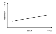
- the ignition timing of CI combustion tends to be delayed as the engine speed increases.
- a certain amount of heat receiving time is required to be exposed to a high temperature environment that induces it, but the time per cycle decreases as the engine speed increases.
- the ratio of the heat receiving time of the unburned mixture in one cycle is increased, and the ignition timing of CI combustion is shifted later by that amount.
- the inventors of the present application increase the temperature before the start of compression in the combustion chamber in accordance with the increase in the engine speed, and quickly induce self-ignition of the unburned mixture in the combustion chamber.
- the inventors have found that it is possible to suppress a delay in the ignition timing of CI combustion, and have completed the technology disclosed herein.
- control device for a compression self-ignition engine includes an engine configured to combust an air-fuel mixture in a combustion chamber, and a fresh air and burned gas that is attached to the engine and is introduced into the combustion chamber.
- a state quantity setting device configured to set the interior of the combustion chamber to a desired state by adjusting the introduction and the residue of the burnt gas in the combustion chamber; and attached to the engine; and An injector configured to inject fuel to be supplied into the combustion chamber, and an ignition disposed to face the combustion chamber and configured to ignite an air-fuel mixture in the combustion chamber
- a plug is connected to each of the state quantity setting device, the injector and the spark plug, and is connected to each of the state quantity setting device, the injector and the spark plug.
- a controller configured to operate the engine by outputting a control signal; and a parameter connected to the controller and related to an operating state of the engine, and a detection signal output to the controller A configured sensor.
- the spark plug receives the control signal of the controller, and when the engine operating state based on the detection signal of the sensor is in a predetermined operating region, the ignited air-fuel mixture burns by flame propagation, Then, the state quantity setting device receives a control signal from the controller, and ignites the mixture at a predetermined ignition timing so that the unburned mixture in the combustion chamber burns by self-ignition.
- the engine speed is The state in the combustion chamber is controlled so that the temperature in the combustion chamber is higher than that in the second rotation region below the predetermined rotation speed.
- combustion chamber here is not limited to the meaning of the space formed when the piston reaches compression top dead center.
- combustion chamber is used in a broad sense.
- the spark plug receives a control signal from the controller and forcibly ignites the air-fuel mixture in the combustion chamber when the engine operating state is in a predetermined operating region.
- the air-fuel mixture is combusted by flame propagation, and then the unburned air-fuel mixture in the combustion chamber is combusted by self-ignition to complete combustion.
- combustion by flame propagation is advantageous in suppressing the generation of combustion noise because the pressure fluctuation is relatively small. Also, by performing CI combustion, the combustion period is shortened and combustion efficiency is improved compared to combustion by flame propagation. Therefore, fuel consumption can be improved while suppressing the generation of combustion noise.
- the state quantity setting device When performing SICI combustion, the state quantity setting device operates to adjust the temperature in the combustion chamber according to the engine speed. That is, when the engine speed is in the first region where the engine speed is relatively high, the state quantity setting device has a higher temperature of the combustion chamber before the start of compression than in the second region where the engine speed is relatively low.
- the state in the combustion chamber is controlled by adjusting the introduction of fresh air and burned gas into the combustion chamber and the residual of burned gas in the combustion chamber so as to be higher.
- the state quantity setting device receives a control signal from the controller, and starts compression in the combustion chamber as the engine speed increases when the operating state of the engine is in the predetermined operating region. At least one of the introduction amount of fresh air into the combustion chamber, the recirculation amount of the burned gas to the intake passage, and the remaining amount of the burned gas in the combustion chamber so that the previous temperature becomes high You may come to adjust.
- the delay in the ignition timing of CI combustion tends to gradually increase as the engine speed increases. If the temperature in the combustion chamber before the start of compression increases as the engine speed increases, the heat reception time of the unburned mixture is advanced to compensate for the delay in the ignition timing of CI combustion.
- the ignition timing of CI combustion can be accurately controlled.
- the state quantity setting device may include an internal EGR (Exhaust Gas Recirculation) system provided in the engine and configured to leave a part of burned gas in the combustion chamber.
- the internal EGR system receives the control signal from the controller, and when the engine operating state is in the predetermined operating region, the internal EGR system is configured to output the second engine when the engine speed is in the first rotating region.
- the burned gas remaining in the combustion chamber may be increased so that the temperature before the start of compression of the air-fuel mixture in the combustion chamber is higher than that in the rotation region.
- ⁇ Burn gas left in the combustion chamber by the internal EGR system is much hotter than fresh air because it contains the amount of heat generated during combustion. Therefore, increasing the amount of burned gas that remains in the combustion chamber contributes to a temperature increase in the combustion chamber before starting compression. Therefore, by increasing the amount of burned gas remaining in the combustion chamber by the internal EGR system, the temperature before the start of compression in the combustion chamber can be increased.
- the internal EGR system receives a control signal from the controller, and when the engine operating state is in the predetermined operating region, the internal EGR system increases the engine speed before the compression starts in the combustion chamber.
- the burned gas remaining in the combustion chamber may be increased so that the temperature of the combustion chamber increases.
- the delay in the ignition timing of CI combustion tends to increase gradually as the engine speed increases.
- the heat reception time of the unburned mixture is advanced to compensate for the delay in the ignition timing of CI combustion.
- the increase / decrease of the burnt gas remaining in the combustion chamber by the internal EGR system is excellent in adjusting the temperature in the combustion chamber, so that the ignition timing of CI combustion can be suitably controlled.
- the state quantity setting device is provided in the engine and lowers the temperature of a part of the burned gas discharged from the combustion chamber to the exhaust passage, and then returns to the intake passage and introduces it into the combustion chamber.
- You may have an external EGR system.
- the external EGR system receives the control signal from the controller, and when the engine operating state is in the predetermined operating region, the external EGR system receives the second signal when the engine speed is in the first rotating region.
- the burned gas introduced into the combustion chamber may be reduced so that the temperature before the compression start in the combustion chamber is higher than that in the rotation region.
- the burned gas introduced into the combustion chamber by the external EGR system has a relatively low temperature because it lowers the temperature when it is returned to the intake passage. Therefore, reducing the amount of burned gas that is recirculated into the combustion chamber contributes to a temperature increase in the combustion chamber before starting compression. Therefore, by reducing the burnt gas introduced into the combustion chamber by the external EGR system, the temperature before the compression start in the combustion chamber can be increased.
- the external EGR system receives a control signal from the controller, and when the engine operating state is in the predetermined operating region, the external EGR system increases the engine speed before the compression start in the combustion chamber.
- the burned gas introduced into the combustion chamber may be reduced so that the temperature of the combustion chamber increases.
- the delay in the ignition timing of CI combustion tends to increase gradually as the engine speed increases.
- the heat reception time of the unburned mixture is advanced to compensate for the delay in the ignition timing of CI combustion.
- the increase / decrease of the burnt gas introduced into the combustion chamber by the external EGR system is excellent in adjusting the temperature in the combustion chamber, so that the ignition timing of CI combustion can be suitably controlled.
- the state quantity setting device has a variable valve mechanism that is provided in the engine and configured to change a valve opening timing of at least one of the intake valve and the exhaust valve in response to a control signal of the controller. You may do it.
- the variable valve mechanism receives a control signal from the controller, and when the engine operating state is in the predetermined operating region, the variable valve mechanism is in the first rotating region when the engine speed is in the first rotating region.
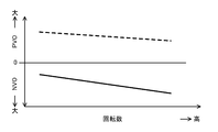
- the overlap period during which both the intake valve and the exhaust valve are opened can be shortened so that the temperature before the start of compression in the combustion chamber is higher than that in the two rotation region. Good.
- an overlap period in which both the intake valve and the exhaust valve are opened is referred to as a “positive overlap period” in order to distinguish it from a negative overlap period in which both the intake valve and the exhaust valve are closed.
- the residual gas in the combustion chamber is scavenged, so the temperature in the combustion chamber before starting compression decreases.
- the scavenging amount of the residual gas pushed out from the combustion chamber changes according to the length of the positive overlap period. If the positive overlap period is shortened, the scavenging amount of the residual gas decreases, and the burned gas remaining in the combustion chamber increases. An increase in the residual amount of burned gas contributes to a temperature increase in the combustion chamber before starting compression. Therefore, by shortening the positive overlap period, the temperature of the combustion chamber before the start of compression can be increased.
- variable valve mechanism receives a control signal from the controller, and starts compression in the combustion chamber as the engine speed increases when the operating state of the engine is in the predetermined operating range.
- the overlap period (positive overlap period) during which both the intake valve and the exhaust valve are opened may be shortened so that the previous temperature becomes high.
- the delay in the ignition timing of CI combustion tends to increase gradually as the engine speed increases.
- the heat reception time of the unburned mixture is advanced according to the degree of delay in the ignition timing of CI combustion.
- the increase and decrease of the scavenging amount of the residual gas according to the positive overlap period provided by the variable valve mechanism is excellent in adjusting the temperature in the combustion chamber, so that the ignition timing of CI combustion should be suitably controlled. Can do.
- the injector may be configured to inject fuel into the combustion chamber.
- the injector receives the control signal from the controller and forms the substantially homogeneous air-fuel mixture in the combustion chamber when the engine operating state is in the predetermined operating region.
- a post-stage injection that injects fuel at a timing close to the predetermined ignition timing and a pre-stage injection that injects fuel at a timing before the post-stage injection and away from the ignition timing. It may be like this.
- the fuel injected by the pre-stage injection is mainly burned by the CI combustion
- the fuel injected by the post-stage injection is mainly burned by the SI combustion.
- SICI combustion stabilization of ignition by a spark plug, stabilization of combustion by flame propagation, and stabilization of ignition by self-ignition are achieved.
- the air-fuel mixture formed in the combustion chamber is substantially homogeneous, it is possible to improve fuel efficiency by reducing unburned loss and to improve exhaust gas performance by avoiding the generation of smoke.
- the injector may execute the pre-stage injection and the post-stage injection within a compression stroke period.
- the controller outputs a control signal to the state quantity setting device and the injector, whereby the state in the combustion chamber is used as an index related to the mass ratio of the total gas and fuel in the combustion chamber.
- G / F may be set to 18.5 or more and 30 or less, and the excess air ratio ⁇ may be set to 1.0 ⁇ 0.2.
- ⁇ SICI combustion combining SI combustion and CI combustion can control the timing of self-ignition with high accuracy. That is, even if the temperature in the combustion chamber before the start of compression varies, the temperature variation before the start of compression can be absorbed by adjusting the calorific value of SI combustion. If the start timing of SI combustion is adjusted by adjusting the ignition timing, for example, according to the temperature in the combustion chamber before the start of compression, the unburned mixture can be self-ignited at a desired timing.
- the timing of self-ignition in order to accurately control the timing of self-ignition, the timing of self-ignition must change in response to changing the ignition timing. It is preferable that the sensitivity at which the self-ignition timing changes is high with respect to the change in the ignition timing.
- the timing of self-ignition can be accurately controlled in SICI combustion in which SI combustion and CI combustion are combined while improving fuel efficiency and exhaust gas performance.
- the engine speed is increased by increasing the temperature of the combustion chamber before the start of compression as the engine speed increases.
- FIG. 1 is a diagram illustrating a configuration of a compression self-ignition engine.
- FIG. 2 is a cross-sectional view illustrating the configuration of the combustion chamber.
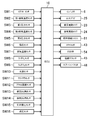
- FIG. 3 is a block diagram illustrating the configuration of the control device for the compression self-ignition engine.
- FIG. 4 is a diagram illustrating an engine operating region.
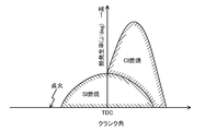
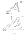
- FIG. 5 is a diagram conceptually showing a change in the heat generation rate of SICI combustion in which SI combustion and CI combustion are combined.
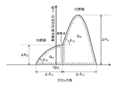
- FIG. 6 is a diagram for explaining the definition of the SI rate in SICI combustion.
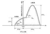
- FIG. 7 is a diagram for explaining the definition of the SI rate in SICI combustion.
- FIG. 1 is a diagram illustrating a configuration of a compression self-ignition engine.
- FIG. 2 is a cross-sectional view illustrating the configuration of the combustion chamber.
- FIG. 3 is a block diagram illustrating the configuration of the control device for the compression self-ignition engine.
- FIG. 4 is a diagram illustrating an engine operating region
- FIG. 8 shows changes in the SI rate, changes in the state quantity in the combustion chamber, changes in the overlap period of the intake valve and the exhaust valve, and changes in the fuel injection timing and ignition timing with respect to the engine load. It is a figure explaining.
- the upper diagram of FIG. 9 is a diagram illustrating a change in the combustion waveform with respect to an increase in engine load in non-supercharged SICI combustion, and the lower diagram in FIG. 9 is an increase in engine load in supercharged SICI combustion. It is a figure which illustrates the change of the combustion waveform with respect to doing.
- FIG. 10 is a flowchart showing a procedure of engine control executed by the ECU.
- FIG. 11 is a diagram illustrating a control concept related to adjustment of the SI rate.
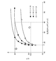
- FIG. 12 shows the G / F of the air-fuel mixture and the desired turbulent flow when the engine is operating at a predetermined load with a low load and only the internal EGR gas is introduced into the combustion chamber. It is a figure which shows the relationship with turbulent energy required in order to implement
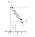
- FIG. 13 is a diagram showing the relationship between the temperature in the combustion chamber that realizes the necessary turbulent energy shown in FIG. 12 and the air-fuel mixture G / F.
- FIG. 14 is a diagram showing the relationship between the pressure in the combustion chamber realizing the necessary turbulent energy shown in FIG. 12 and the air-fuel mixture G / F.
- FIG. 13 is a diagram showing the relationship between the temperature in the combustion chamber that realizes the necessary turbulent energy shown in FIG. 12 and the air-fuel mixture G / F.
- FIG. 14 is a diagram showing the relationship between the pressure in the combustion chamber realizing the necessary turbulent energy shown in FIG. 12 and the air-fuel mixture G / F.
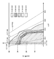
- FIG. 15 is a contour diagram on a plane in which the vertical axis represents the EGR rate of the air-fuel mixture and the horizontal axis represents the A / F of the air-fuel mixture, illustrating the ratio of change in the self-ignition timing with respect to the change in ignition timing in SICI combustion. is there.
- FIG. 16 is a diagram illustrating a change in the residual amount of internal EGR gas remaining in the combustion chamber with respect to the engine speed in the second medium load region.
- FIG. 17 is a diagram exemplifying a change in the introduction amount of the external EGR gas introduced into the combustion chamber with respect to the engine speed in the second medium load region.
- FIG. 18 is a diagram illustrating a change in the internal EGR rate with respect to the engine speed in the second medium load region.
- FIG. 19 is a diagram illustrating a change in the positive overlap period in the second medium load region and a change in the negative overlap period in the first medium load region with respect to the engine speed.
- FIG. 1 is a diagram illustrating a configuration of a compression self-ignition engine.
- FIG. 2 is a cross-sectional view illustrating the configuration of the combustion chamber.
- the intake side is the left side of the drawing, and the exhaust side is the right side of the drawing.
- the intake side in FIG. 2 is the right side of the drawing, and the exhaust side is the left side of the drawing.
- FIG. 3 is a block diagram illustrating the configuration of the control device for the compression self-ignition engine.
- Engine 1 is mounted on a four-wheeled vehicle. The vehicle travels when the engine 1 is driven.
- the fuel of the engine 1 is gasoline in this configuration example.
- the fuel may be gasoline containing bioethanol or the like.
- the fuel of the engine 1 may be any fuel as long as it is a liquid fuel containing at least gasoline.
- the engine 1 includes a cylinder block 12 and a cylinder head 13 placed on the cylinder block 12. A plurality of cylinders 11 are formed inside the cylinder block 12. 1 and 2, only one cylinder 11 is shown.
- the engine 1 is a multi-cylinder engine.
- the piston 3 is slidably inserted in each cylinder 11.
- the piston 3 is connected to the crankshaft 15 via a connecting rod 14.
- the piston 3 defines a combustion chamber 17 together with the cylinder 11 and the cylinder head 13.
- the “combustion chamber” is not limited to the meaning of the space formed when the piston 3 reaches compression top dead center.
- the term “combustion chamber” may be used in a broad sense. That is, the “combustion chamber” may mean a space formed by the piston 3, the cylinder 11, and the cylinder head 13 regardless of the position of the piston 3.
- the upper surface of the piston 3 is a flat surface.
- a cavity 31 is formed on the upper surface of the piston 3.
- the cavity 31 is recessed from the upper surface of the piston 3.
- the cavity 31 has a shallow dish shape.
- the cavity 31 faces an injector 6 described later when the piston 3 is positioned near the compression top dead center.
- the cavity 31 has a convex portion 311.
- the convex portion 311 is provided on the central axis X of the cylinder 11.
- the convex part 311 is substantially conical.
- the convex portion 311 extends upward from the bottom of the cavity 31 along the central axis X of the cylinder 11.
- the upper end of the convex portion 311 is almost the same height as the upper surface of the cavity 31.
- the cavity 31 also has a concave portion 312 provided around the convex portion 311.
- the recessed portion 312 is provided so as to surround the entire circumference of the protruding portion 311.
- the cavity 31 has a symmetrical shape with respect to the central axis X.
- the peripheral side surface of the recessed portion 312 is inclined with respect to the central axis X from the bottom surface of the cavity 31 toward the opening of the cavity 31.
- the inner diameter of the cavity 31 in the recessed portion 312 gradually increases from the bottom of the cavity 31 toward the opening of the cavity 31.
- the lower surface of the cylinder head 13, that is, the ceiling surface of the combustion chamber 17, is constituted by an inclined surface 1311 and an inclined surface 1312 as shown in FIG.
- the inclined surface 1311 has an upward slope from the intake side toward the central axis X.
- the inclined surface 1312 has an upward slope from the exhaust side toward the central axis X.
- the ceiling surface of the combustion chamber 17 has a so-called pent roof shape.
- the shape of the combustion chamber 17 is not limited to the shape illustrated in FIG.
- the shape of the cavity 31, the shape of the upper surface of the piston 3, the shape of the ceiling surface of the combustion chamber 17, and the like can be changed as appropriate.
- the geometric compression ratio of the engine 1 is set high for the purpose of improving the theoretical thermal efficiency and stabilizing the CI (Compression Ignition) combustion described later.
- the geometric compression ratio of the engine 1 is 17 or more.
- the geometric compression ratio may be 18, for example. What is necessary is just to set a geometric compression ratio suitably in the range of 17-20.
- the cylinder head 13 has two intake ports 18 for each cylinder 11.
- the intake port 18 communicates with the combustion chamber 17.
- An intake valve 21 is disposed in the intake port 18.
- the intake valve 21 opens and closes between the combustion chamber 17 and the intake port 18.
- the intake valve 21 is opened and closed at a predetermined timing by an intake valve mechanism.
- the intake valve mechanism has an intake electric VVT (Variable Valve Timing) 23 that is a variable valve mechanism as shown in FIG.
- the intake electric VVT 23 is configured to continuously change the rotation phase of the intake camshaft within a predetermined angle range. Thereby, the valve opening timing and the valve closing timing of the intake valve 21 are continuously changed.
- the intake valve mechanism may have a hydraulic VVT instead of the electric VVT.
- the cylinder head 13 is also formed with two exhaust ports 19 for each cylinder 11.
- the exhaust port 19 communicates with the combustion chamber 17.
- An exhaust valve 22 is disposed in the exhaust port 19.
- the exhaust valve 22 opens and closes between the combustion chamber 17 and the exhaust port 19.
- the exhaust valve 22 is opened and closed at a predetermined timing by an exhaust valve mechanism.
- the exhaust valve mechanism has an exhaust electric VVT 24 that is a variable valve mechanism as shown in FIG.
- the exhaust electric VVT 24 is configured to continuously change the rotation phase of the exhaust camshaft within a predetermined angle range. Thereby, the valve opening timing and the valve closing timing of the exhaust valve 22 continuously change.
- the exhaust valve mechanism may have a hydraulic VVT instead of the electric VVT.
- the engine 1 adjusts the length of the overlap period related to the opening timing of the intake valve 21 and the closing timing of the exhaust valve 22 by the intake electric VVT 23 and the exhaust electric VVT 24.
- the residual gas in the combustion chamber 17 is scavenged, or hot burned gas is confined in the combustion chamber 17 (that is, the internal EGR (Exhaust Gas Recirculation) gas is left in the combustion chamber 17).
- the intake electric VVT 23 and the exhaust electric VVT 24 constitute an internal EGR system 55A as one of state quantity setting devices. Note that the internal EGR system 55A is not necessarily configured by VVT.
- An injector 6 is attached to the cylinder head 13 for each cylinder 11.
- the injector 6 is configured to inject fuel directly into the combustion chamber 17.
- the injector 6 is disposed in a valley portion of the pent roof where the intake-side inclined surface 1311 and the exhaust-side inclined surface 1312 intersect. As shown in FIG. 2, the injector 6 is disposed such that its injection axis is along the central axis X.
- the injection axis of the injector 6 coincides with the position of the convex portion 311 of the cavity 31.
- the injector 6 faces the cavity 31.
- the injection axis of the injector 6 may be shifted from the central axis X of the cylinder 11. Even in this case, it is desirable that the injection axis of the injector 6 and the position of the convex portion 311 of the cavity 31 coincide with each other.
- the injector 6 is constituted by a multi-injection type fuel injection valve having a plurality of injection holes.
- the injector 6 injects fuel so that the fuel spray spreads radially from the center of the combustion chamber 17 as indicated by arrows in FIG.
- the injector 6 may inject fuel at the timing when the piston 3 is positioned near the compression top dead center.
- the fuel spray flows downward along the convex portion 311 of the cavity 31 while mixing with fresh air, and along the bottom surface and the peripheral side surface of the concave portion 312, the combustion chamber. From the center of 17, it spreads radially outward in the radial direction. Thereafter, the air-fuel mixture reaches the opening of the cavity 31 and flows from the radially outer side toward the center of the combustion chamber 17 along the inclined surface 1311 on the intake side and the inclined surface 1312 on the exhaust side.
- the injector 6 is not limited to a multi-hole injector.
- the injector 6 may employ an external valve opening type injector.
- the fuel supply system 61 is connected to the injector 6.
- the fuel supply system 61 includes a fuel tank 63 configured to store fuel, and a fuel supply path 62 that connects the fuel tank 63 and the injector 6 to each other.
- a fuel pump 65 and a common rail 64 are interposed in the fuel supply path 62.
- the fuel pump 65 pumps fuel to the common rail 64.
- the fuel pump 65 is a plunger-type pump driven by the crankshaft 15.
- the common rail 64 is configured to store the fuel pumped from the fuel pump 65 at a high fuel pressure. When the injector 6 is opened, the fuel stored in the common rail 64 is injected into the combustion chamber 17 from the injection port of the injector 6.
- the fuel supply system 61 is configured to be able to supply high pressure fuel of 30 MPa or more to the injector 6.
- the maximum fuel pressure of the fuel supply system 61 may be about 120 MPa, for example.
- the pressure of the fuel supplied to the injector 6 may be changed according to the operating state of the engine 1.
- the configuration of the fuel supply system 61 is not limited to the above configuration.
- a spark plug 25 is attached to the cylinder head 13 for each cylinder 11.
- the spark plug 25 forcibly ignites the air-fuel mixture in the combustion chamber 17.
- the spark plug 25 is disposed on the intake side across the center axis X1 of the cylinder 11.
- the spark plug 25 is located between the two intake ports 18.
- the spark plug 25 is attached to the cylinder head 13 so as to be inclined from the top to the bottom toward the center of the combustion chamber 17. As shown in FIG. 2, the electrode of the spark plug 25 faces the combustion chamber 17 and is located near the ceiling surface of the combustion chamber 17.
- An intake passage 40 is connected to one side of the engine 1.
- the intake passage 40 communicates with the intake port 18 of each cylinder 11.
- the intake passage 40 is a passage through which gas introduced into the combustion chamber 17 flows.
- An air cleaner 41 that filters fresh air is disposed at the upstream end of the intake passage 40.
- a surge tank 42 is disposed near the downstream end of the intake passage 40.
- a throttle valve 43 is disposed between the air cleaner 41 and the surge tank 42 in the intake passage 40.
- the throttle valve 43 is configured to adjust the amount of fresh air introduced into the combustion chamber 17 by adjusting the opening of the valve.
- the throttle valve 43 constitutes one of state quantity setting devices.
- a supercharger 44 is disposed downstream of the throttle valve 43.
- the supercharger 44 is configured to supercharge the gas introduced into the combustion chamber 17.
- the supercharger 44 is a mechanical supercharger driven by the engine 1.
- the mechanical supercharger 44 may be, for example, a roots type.
- the configuration of the mechanical supercharger 44 may be any configuration.
- the mechanical supercharger 44 may be a Rishorum type or a centrifugal type.
- An electromagnetic clutch 45 is interposed between the supercharger 44 and the engine 1.
- the electromagnetic clutch 45 transmits a driving force from the engine 1 to the supercharger 44 between the supercharger 44 and the engine 1 or interrupts the transmission of the driving force.
- the supercharger 44 is switched on and off. That is, in the engine 1, the supercharger 44 can switch between supercharging the gas introduced into the combustion chamber 17 and the supercharger 44 not supercharging the gas introduced into the combustion chamber 17. It is configured to be able to.
- An intercooler 46 is disposed downstream of the supercharger 44 in the intake passage 40.
- the intercooler 46 is configured to cool the gas compressed in the supercharger 44.
- the intercooler 46 may be configured to be, for example, a water cooling type.
- a bypass passage 47 is connected to the intake passage 40.
- the bypass passage 47 connects the upstream portion of the supercharger 44 and the downstream portion of the intercooler 46 in the intake passage 40 so as to bypass the supercharger 44 and the intercooler 46.
- An air bypass valve 48 is disposed in the bypass passage 47. The air bypass valve 48 adjusts the flow rate of the gas flowing through the bypass passage 47.
- the air bypass valve 48 is fully opened. As a result, the gas flowing through the intake passage 40 bypasses the supercharger 44 and is introduced into the combustion chamber 17 of the engine 1.
- the engine 1 is operated in a non-supercharged state, that is, in a natural intake state.
- the supercharger 44 When the supercharger 44 is turned on (that is, when the electromagnetic clutch 45 is connected), part of the gas that has passed through the supercharger 44 flows backward through the bypass passage 47 upstream of the supercharger. . Since the reverse flow rate can be adjusted by adjusting the opening degree of the air bypass valve 48, the supercharging pressure of the gas introduced into the combustion chamber 17 can be adjusted.
- the supercharger 44, the bypass passage 47, and the air bypass valve 48 constitute a supercharging system 49.
- the air bypass valve 48 constitutes one of state quantity setting devices.
- the exhaust passage 50 is connected to the other side of the engine 1.
- the exhaust passage 50 communicates with the exhaust port 19 of each cylinder 11.
- the exhaust passage 50 is a passage through which exhaust gas discharged from the combustion chamber 17 flows.
- the upstream portion of the exhaust passage 50 constitutes an independent passage branched for each cylinder 11.
- the upstream end of the independent passage is connected to the exhaust port 19 of each cylinder 11.
- An exhaust gas purification system having one or more catalytic converters 51 is disposed in the exhaust passage 50.
- the catalytic converter 51 includes a three-way catalyst. Note that the exhaust gas purification system is not limited to the one containing only the three-way catalyst.
- the EGR passage 52 constituting the external EGR system 55B is connected between the intake passage 40 and the exhaust passage 50.
- the EGR passage 52 is a passage for returning a part of burned gas to the intake passage 40.
- the upstream end of the EGR passage 52 is connected downstream of the catalytic converter 51 in the exhaust passage 50.
- the downstream end of the EGR passage 52 is connected to the upstream side of the supercharger 44 in the intake passage 40.
- a water-cooled EGR cooler 53 is disposed in the EGR passage 52.
- the EGR cooler 53 is configured to cool the burned gas.
- An EGR valve 54 is also disposed in the EGR passage 52.
- the EGR valve 54 is configured to adjust the flow rate of burnt gas flowing through the EGR passage 52. By adjusting the opening degree of the EGR valve 54, the recirculation amount of the cooled burned gas, that is, the external EGR gas can be adjusted.
- the EGR system 55 includes an external EGR system 55B configured to include the EGR passage 52 and the EGR valve 54, and an internal EGR system 55A configured to include the intake electric VVT 23 and the exhaust electric VVT 24 described above. And is composed of.
- the external EGR system 55B (EGR valve 54) constitutes one of state quantity setting devices.
- the control device for the compression self-ignition engine includes an ECU (Engine Control Unit) 10 for operating the engine 1.
- the ECU 10 is a controller based on a well-known microcomputer and includes a central processing unit (CPU) that executes a program and, for example, a RAM (Random Access Memory) or a ROM (Read Only Memory). A memory for storing programs and data, and an input / output bus for inputting and outputting electrical signals.
- the ECU 10 is an example of a controller.
- the ECU 10 is connected to various sensors SW1 to SW16 as shown in FIGS.
- the sensors SW1 to SW16 output detection signals to the ECU 10.
- the sensors include the following sensors.
- the air flow sensor SW1 that is disposed downstream of the air cleaner 41 in the intake passage 40 and detects the flow rate of fresh air flowing through the intake passage 40
- the first intake temperature sensor SW2 that detects the temperature of fresh air
- the intake passage 40 the first pressure sensor SW3 that is disposed downstream of the connection position of the EGR passage 52 and upstream of the supercharger 44 and detects the pressure of the gas flowing into the supercharger 44, and supercharging in the intake passage 40
- the second intake air temperature sensor SW4 which is disposed downstream of the machine 44 and upstream of the connection position of the bypass passage 47 and detects the temperature of the gas flowing out from the supercharger 44, is attached to the surge tank 42, and A second pressure sensor SW5 for detecting the pressure of the gas downstream of the feeder 44, attached to the cylinder head 13 corresponding to each cylinder 11, and each A finger pressure sensor SW6 that detects the pressure in the firing chamber 17 and the exhaust passage 50 and is disposed upstream of the catalytic converter 51 in the exhaust passage 50 and an exhaust temperature sensor SW7 that
- Accelerator position sensor SW12 for detecting the corresponding accelerator position
- engine And an intake cam angle sensor SW13 that detects the rotation angle of the intake camshaft, an exhaust cam angle sensor SW14 that is attached to the engine 1 and detects the rotation angle of the exhaust camshaft, and an EGR passage 52.
- an EGR differential pressure sensor SW15 that detects a differential pressure upstream and downstream of the EGR valve 54
- a fuel pressure sensor SW16 that is attached to the common rail 64 of the fuel supply system 61 and detects the pressure of the fuel supplied to the injector 6 is there.
- the ECU10 judges the driving
- the ECU 100 sends a control signal related to the calculated control amount to the electromagnetic clutch 45 of the injector 6, spark plug 25, intake electric VVT 23, exhaust electric VVT 24, fuel supply system 61, throttle valve 43, EGR valve 54, and supercharger 44. And output to the air bypass valve 48.
- the ECU 10 adjusts the boost pressure by adjusting the opening of the air bypass valve 48 based on the differential pressure across the turbocharger 44 obtained from the detection signals of the first pressure sensor SW3 and the second pressure sensor SW5. adjust.
- the ECU 10 adjusts the opening degree of the EGR valve 54 based on the differential pressure across the EGR valve 54 obtained from the detection signal of the EGR differential pressure sensor SW15, whereby the amount of external EGR gas introduced into the combustion chamber 17 is adjusted. Adjust. Details of control of the engine 1 by the ECU 10 will be described later.
- FIG. 4 illustrates an operation region of the engine 1.
- the operating region of the engine 1 is roughly divided into three regions with respect to the load level. Specifically, the three regions include a low load region (A) including idle operation, a high load region (C) including a fully open load, and a low load region (A) and a high load region (C). It is a medium load region (B).
- the engine 1 performs combustion by compression self-ignition in an intermediate load region with the main purpose of improving fuel consumption and exhaust gas performance.
- combustion modes in each of the low load region, the medium load region, and the high load region will be described in order.
- the combustion mode when the operating state of the engine 1 is in the low load region is SI (Spark Ignition) combustion in which the air-fuel mixture is combusted by flame propagation when the spark plug 25 ignites the air-fuel mixture in the combustion chamber 17. is there.
- SI Spark Ignition
- the A / F of the air-fuel mixture may be set within the purification window of the three-way catalyst. Therefore, the excess air ratio ⁇ of the air-fuel mixture may be set to 1.0 ⁇ 0.2.
- the EGR system 55 introduces EGR gas into the combustion chamber 17 when the operating state of the engine 1 is in a low load region.
- the G / F of the air-fuel mixture that is, the mass ratio of the total gas and fuel in the combustion chamber 17 is set to 18.5 or more and 30 or less.
- the mixture is EGR lean.
- the dilution ratio of the mixture is high. If the G / F of the air-fuel mixture is set to 25, for example, SI combustion can be performed stably in the low load operation region without causing the air-fuel mixture to self-ignite. In the low load region, the G / F of the air-fuel mixture is kept constant regardless of the load level of the engine 1. By doing so, SI combustion is stabilized throughout the low load region. Further, the fuel efficiency of the engine 1 is improved and the exhaust gas performance is improved.
- the engine 1 executes throttling for adjusting the opening degree of the throttle valve 43 and / or a mirror cycle for delaying the closing timing of the intake valve 21 after the intake bottom dead center.
- combustion temperature of the air-fuel mixture and the temperature of the exhaust gas may be increased by further reducing the gas filling amount in the low load and low rotation range within the low load range. This is advantageous in maintaining the catalytic converter 51 in an active state.
- the engine 1 performs SICI combustion combining SI combustion and CI combustion in the medium load region.
- SICI combustion when the spark plug 25 forcibly ignites the air-fuel mixture in the combustion chamber 17, the air-fuel mixture is combusted by flame propagation, and the temperature in the combustion chamber 17 is increased by the heat generated by SI combustion. By becoming high, the unburned air-fuel mixture burns by self-ignition.
- the calorific value of the SI combustion By adjusting the calorific value of the SI combustion, the temperature variation in the combustion chamber 17 before the start of compression can be absorbed. Even if the temperature in the combustion chamber 17 before the start of compression varies, the self-ignition timing can be controlled by adjusting the SI combustion start timing by adjusting the ignition timing, for example.
- the timing of self-ignition In SICI combustion, in order to accurately control the timing of self-ignition, the timing of self-ignition must change in response to changing the ignition timing. It is preferable that the sensitivity at which the self-ignition timing changes is high with respect to the change in the ignition timing.
- the ⁇ of the air-fuel mixture is 1.0 ⁇ 0.2 and the G / F of the air-fuel mixture is 18.5 or more and 30 or less, self- It turns out that the timing of ignition changes. Therefore, when the operating state of the engine 1 is in the medium load region, the engine 1 is in a state in the combustion chamber 17 where the ⁇ of the mixture is 1.0 ⁇ 0.2 and the G / F of the mixture is Set to 18.5 or more and 30 or less.
- ⁇ By controlling the timing of self-ignition with high accuracy, an increase in combustion noise can be avoided when the operating state of the engine 1 is in the middle load region. Further, by performing the CI combustion with the dilution ratio of the air-fuel mixture as high as possible, the fuel efficiency performance of the engine 1 can be enhanced. Furthermore, by setting ⁇ of the air-fuel mixture to 1.0 ⁇ 0.2, it becomes possible to purify the exhaust gas by the three-way catalyst, so that the exhaust gas performance of the engine 1 becomes good.
- the G / F of the mixture is set to 18.5 or more and 30 or less (for example, 25), and ⁇ of the mixture is set to 1.0 ⁇ 0.2.
- the state quantity in the combustion chamber 17 does not fluctuate greatly between when the operating state of the engine 1 is in the low load region and when it is in the medium load region. Therefore, the robustness of the control of the engine 1 against the change in the load of the engine 1 is enhanced.
- the medium load region (B) is a region that is higher than the predetermined load, and is a first medium load region (B1) that performs supercharging, and a region that is below the predetermined load and that does not perform supercharging. It is divided into a medium load region (B2).
- the predetermined load is, for example, a 1 ⁇ 2 load.
- the second medium load region is a region having a lower load than the first medium load region.
- the combustion mode in the first medium load region may be referred to as supercharging SICI combustion
- the combustion mode in the second medium load region may be referred to as non-supercharging SICI combustion.
- the engine 1 adjusts the amount of fresh air introduced into the combustion chamber 17 by adjusting the amount of EGR gas introduced into the combustion chamber 17. .
- the state quantity in the combustion chamber 17 is substantially constant, for example, ⁇ of the air-fuel mixture is 1.0, while the G / F of the air-fuel mixture is changed in the range of 25 to 28.
- the engine 1 increases both fresh air and EGR gas introduced into the combustion chamber 17 as the fuel amount increases.
- the G / F of the air-fuel mixture is constant even when the load on the engine 1 increases.
- the state quantity in the combustion chamber 17 is, for example, ⁇ of the air-fuel mixture becomes substantially constant at 1.0, and G / F of the air-fuel mixture is constant at 25.
- the combustion mode when the operating state of the engine 1 is in the high load region is SI combustion.
- the combustion mode in the high load region may be referred to as high load SI combustion.
- the ⁇ of the air-fuel mixture is 1.0 ⁇ 0.2.
- the G / F of the air-fuel mixture is basically set to 18.5 or more and 30 or less.
- the opening degree of the throttle valve 43 is fully open, and the supercharger 44 performs supercharging.
- the engine 1 reduces the amount of EGR gas as the load increases.
- the G / F of the air-fuel mixture decreases as the load on the engine 1 increases. Since the amount of fresh air introduced into the combustion chamber 17 is increased by the amount of EGR gas reduced, the amount of fuel can be increased. This is advantageous in increasing the maximum output of the engine 1.
- the G / F of the air-fuel mixture may be about 17 near the fully open load.
- the G / F of the air-fuel mixture may be changed, for example, in the range of 17 to 25 in the high load region. Therefore, the G / F of the air-fuel mixture may be changed in the range of 17 to 30 in the entire operation region of the engine 1 including the low load region, the medium load region, and the high load region.
- the state quantity in the combustion chamber 17 does not fluctuate greatly between when the operating state of the engine 1 is in the high load region and when it is in the medium load region. The robustness of the control of the engine 1 against the change of the load of the engine 1 is increased.
- the engine 1 performs SI combustion in a high load region, but there is a problem that abnormal combustion such as pre-ignition and knocking is likely to occur due to a high geometric compression ratio and the like. .
- the engine 1 is configured to avoid abnormal combustion by devising the form of fuel injection in a high load region.
- the ECU 10 injects fuel into the combustion chamber 17 at a high fuel pressure of 30 MPa or more and at a timing within a period from the latter stage of the compression stroke to the early stage of the expansion stroke (hereinafter, this period is referred to as a retard period).
- a control signal is output to the fuel supply system 61 and the injector 6.
- the ECU 10 also outputs a control signal to the spark plug 25 so that the air-fuel mixture is ignited at a timing near the compression top dead center after fuel injection.
- injecting fuel into the combustion chamber 17 at a high fuel pressure and at a timing within the retard period is referred to as high-pressure retarded injection.
- the reaction time of the air-fuel mixture includes (1) a period during which the injector 6 injects fuel (that is, an injection period), and (2) after the fuel injection is completed, This is a time obtained by adding the period until formation (that is, the mixture formation period) and (3) the period until SI combustion started by ignition ends ((3) combustion period).
- the injection period and the mixture formation period are shortened.
- the timing for starting fuel injection can be made closer to the ignition timing.
- the fuel is injected at the timing within the retard period from the latter stage of the compression stroke to the early stage of the expansion stroke.
- High-pressure retarded injection can shorten the injection period, the mixture formation period, and the combustion period. Compared with the case where fuel is injected into the combustion chamber 17 during the intake stroke, the high-pressure retarded injection can greatly shorten the time for the air-fuel mixture to react. In the high pressure retarded injection, the time for which the air-fuel mixture reacts is shortened, so that abnormal combustion can be avoided.
- the fuel pressure is set to 30 MPa or more, for example, the injection period, the mixture formation period, and the combustion period can be effectively shortened.
- the fuel pressure is preferably set as appropriate according to the properties of the fuel.
- the upper limit value of the fuel pressure may be 120 MPa.
- the high-pressure retarded injection also injects fuel into the combustion chamber 17 only after the compression top dead center is reached. Therefore, in the compression stroke, in the combustion chamber 17, a gas that does not contain fuel, in other words, a specific heat ratio. High gas is compressed. If high-pressure retarded injection is performed when the rotational speed of the engine 1 is high, the temperature in the combustion chamber 17 at the compression top dead center, that is, the compression end temperature becomes high. An increase in the compression end temperature may cause abnormal combustion such as knocking.
- the high load region (C) is divided into the first high load region (C1) on the low rotation side and the second high load region (C2) having a higher rotational speed than the first high load region (C1). ).
- the first high load region may include a low rotation region and a medium rotation region when the high load region is divided into three regions of low rotation, medium rotation, and high rotation.
- the second high load region may include a high rotation region obtained by dividing the inside of the high load region into three regions of low rotation, medium rotation, and high rotation.
- the injector 6 receives the control signal of the ECU 10 and performs the above-described high-pressure retarded injection.
- the injector 6 receives a control signal from the ECU 10 and injects fuel at a predetermined timing during the intake stroke.
- the fuel injection performed during the intake stroke does not require high fuel pressure.
- the ECU 10 outputs a control signal to the fuel supply system 61 so that the fuel pressure is lower than the fuel pressure of the high pressure retarded injection (for example, the fuel pressure is less than 40 MPa). By reducing the fuel pressure, the mechanical resistance loss of the engine 1 is reduced, which is advantageous for improving fuel consumption.
- the specific heat ratio of the gas in the combustion chamber 17 is lowered, so that the compression end temperature is lowered. Since the compression end temperature becomes low, the engine 1 can avoid abnormal combustion. Since it is not necessary to retard the ignition timing in order to avoid abnormal combustion, in the second high load region, the spark plug 25 is mixed at the timing near the compression top dead center, as in the first high load region. I ignite my mind.
- the air-fuel mixture does not reach self-ignition due to the high-pressure retarded injection, so the engine 1 can perform stable SI combustion.
- the air-fuel mixture does not reach self-ignition due to fuel injection during the intake stroke, and therefore the engine 1 can perform stable SI combustion.
- the turbulent combustion speed includes the air-fuel ratio (or excess air ratio ⁇ ) of the mixture, the EGR (ExhaustExGashausRecirculation) rate (that is, the dilution rate) of the mixture, the temperature and pressure in the combustion chamber 17, and the combustion chamber. 17 is affected by turbulent energy and the like.
- the inventors of the present application have an excess air ratio ⁇ of the air-fuel mixture, a dilution ratio of the air-fuel mixture (here, the total gas in the combustion chamber 17). (G / F which is the mass ratio of the fuel and the fuel), the temperature and pressure in the combustion chamber 17, and the turbulent energy in the combustion chamber 17 were studied by simulation.
- the conditions for this simulation are conditions in which the engine 1 is operating at a low load and the temperature in the combustion chamber 17 is made as high as possible by introducing only the internal EGR gas into the combustion chamber 17. .
- the lower limit of the G / F of the air-fuel mixture is 18.5. Further, if such a lean air-fuel ratio is used and a three-way catalyst is used to prevent NOx emission, the excess air ratio ⁇ of the air-fuel mixture is 1.0 ⁇ 0.2.
- the G / F of the air-fuel mixture is large.
- the inventors of the present application examined the relationship between the G / F of the air-fuel mixture and the turbulent energy necessary to realize a desired turbulent combustion speed.
- the engine 1 has a rotational speed of 2000 rpm and is operating at a low load. Further, an internal EGR gas is introduced into the combustion chamber 17.
- the closing timing of the intake valve 21 is 91 ° ABDC.
- the geometric compression ratio of the engine 1 is 18.
- the characteristic line of G / F when ⁇ of the air-fuel mixture is 1.2 becomes a saturation curve that saturates around 30.
- the turbulent energy can be 40 m 2 / s 2 . It was newly found that even when turbulent energy exceeding 40 m 2 / s 2 is realized, the G / F of the air-fuel mixture hardly becomes larger than 30.
- the upper limit of the G / F of the air-fuel mixture is 30.
- the range of turbulent energy required for stabilizing SI combustion when ⁇ of the air-fuel mixture is 1.0 or 1.2 and the range of G / F is 18.5 or more and 30 or less. Is 17 to 40 m 2 / s 2 .
- FIG. 13 shows the relationship between the temperature at the ignition timing and the G / F of the air-fuel mixture in the combustion chamber 17 necessary to achieve a desired turbulent combustion speed under the same conditions as FIG. Yes.
- the required temperature TIg (K) in the combustion chamber 17 at the ignition timing is 570 to 800K.
- FIG. 14 shows the relationship between the pressure at the ignition timing and the G / F of the air-fuel mixture in the combustion chamber 17 necessary for realizing the desired turbulent combustion speed under the same conditions as FIG. Yes.
- the required pressure PIg (kPa) in the combustion chamber 17 at the ignition timing is 400 to 920 kPa.
- the change ratio indicates the magnitude of the change in the crank angle at the self-ignition timing when the ignition timing is changed by 1 ° in the crank angle. The larger the change ratio value, the higher the self-ignition timing change sensitivity with respect to the ignition timing change, and the smaller the change ratio value, the lower the self-ignition timing change sensitivity with respect to the ignition timing change.
- the vertical axis represents the EGR rate of the air-fuel mixture
- the horizontal axis represents the A / F of the air-fuel mixture.
- the change sensitivity of the self-ignition timing with respect to the change in the ignition timing is lower in the upper right part of the figure, and the change sensitivity of the self-ignition timing is higher in the lower left part of the figure. From FIG. 15, the range surrounded by a broken line in which the ⁇ of the air-fuel mixture is 1.0 ⁇ 0.2 and the G / F range is 18.5 or more and 30 or less is self-ignition with respect to the change of the ignition timing. It can be seen that the timing changes.
- the upper limit of the EGR rate is preferably 40% from the viewpoint of combustion stability.
- FIG. 5 shows a waveform illustrating the change in the heat generation rate with respect to the crank angle in SICI combustion.
- the unburned mixture self-ignites.
- the slope of the heat generation rate waveform changes from small to large near the compression top dead center. That is, the heat generation rate waveform has an inflection point at the timing when CI combustion starts.
- dp / d ⁇ can be used as an index representing combustion noise. As described above, since SICI combustion can reduce dp / d ⁇ , it is possible to avoid excessive combustion noise. . Combustion noise can be suppressed below an acceptable level.
- SICI combustion can achieve both prevention of combustion noise and improvement of fuel efficiency.
- SI rate is defined as a parameter indicating the characteristics of SICI combustion.
- the SI rate is a ratio between SI combustion and CI combustion in SICI combustion combining SI combustion and CI combustion. When the SI rate is high, the SI combustion rate is high, and when the SI rate is low, the CI combustion rate is high.
- the SI rate is not limited to the above definition. Various definitions can be considered for the SI rate.
- the waveform of the heat generation rate has an inflection point at the timing when CI combustion starts. Therefore, as shown in FIG. 6, the inflection point in the waveform of the heat generation rate may be used as a boundary, the range on the advance side of the boundary may be SI combustion, and the range on the retard side may be CI combustion.
- the SI rate may be defined on the basis of a part of the area rather than the entire area on the advance side from the boundary and a part of the area on the retard side from the boundary.
- SI rate ⁇ P SI / ( ⁇ P SI + ⁇ P CI ) may be calculated from the peak ⁇ P SI of the heat generation rate in the range on the advance side from the boundary and the peak ⁇ P CI of the heat generation rate in the range on the retard side.
- SI rate ⁇ P SI / ⁇ P CI .
- the SI rate ⁇ SI / ( ⁇ SI + ⁇ CI ) may be calculated from the slope ⁇ SI of the heat generation rate in the advance angle range from the boundary and the slope ⁇ CI of the heat generation rate in the retard angle range.
- the SI rate may be ⁇ SI / ⁇ CI .
- the SI rate is defined from the magnitude of the generation rate) or the slope (that is, the rate of change of the heat generation rate).
- the SI rate is similarly defined from the area, the length of the horizontal axis, the length of the vertical axis, or the slope. Also good.
- the inflection point of the combustion waveform related to the heat generation rate or pressure does not always appear clearly.
- the following definition may be used as the definition of the SI rate that is not based on the inflection point. That is, as shown in FIG. 7, in the combustion waveform, the range on the advance side from the compression top dead center (TDC) may be SI combustion, and the range on the retard side from the compression top dead center may be CI combustion.
- the area (Q SI , Q CI ), the length of the horizontal axis ( ⁇ SI , ⁇ CI ), the length of the vertical axis ( ⁇ P SI , ⁇ P CI ), or the slope ( ⁇ SI , ⁇ CI ), the SI rate may be defined.
- the SI rate may be defined not based on the combustion waveform actually performed in the combustion chamber 17 but based on the fuel amount.
- split injection including front-stage injection and rear-stage injection is performed in the middle load region where SICI combustion is performed.
- the fuel injected into the combustion chamber 17 by the post-injection is not diffused in the combustion chamber 17 and is positioned in the vicinity of the spark plug 25 because the time from injection to ignition is short. Therefore, the fuel injected into the combustion chamber 17 by the post-stage injection mainly burns by SI combustion.
- the fuel injected into the combustion chamber 17 by the pre-stage injection mainly burns by CI combustion.
- the engine 1 switches between SI combustion and SICI combustion according to the operating state.
- the engine 1 also changes the SI rate according to the operating state of the engine 1. Since the operating range in which combustion is performed by self-ignition is expanded, the engine 1 is compatible with both suppressing the generation of combustion noise and improving fuel consumption.
- FIG. 8 shows changes in the SI rate, changes in the state quantity in the combustion chamber 17, changes in the intake valve opening period and the exhaust valve opening period, and fuel injection timing with respect to the load of the engine 1 And changes in ignition timing are illustrated.
- the operation control of the engine 1 will be described on the assumption that the load of the engine 1 gradually increases at a predetermined rotational speed.
- Low load area low load SI combustion
- the SI rate is constant at 100%.
- the G / F of the air-fuel mixture is kept constant between 18.5 and 30 as described above.
- the engine 1 introduces fresh air and burned gas in an amount corresponding to the amount of fuel into the combustion chamber 17. As described above, the amount of fresh air introduced is adjusted by throttling and / or mirror cycles. Since the dilution rate is high, the temperature in the combustion chamber 17 is increased in order to stabilize the SI combustion.
- the engine 1 introduces internal EGR gas into the combustion chamber 17 in a low load region.
- the internal EGR gas is introduced into the combustion chamber 17 by providing a negative overlap period in which both the intake valve 21 and the exhaust valve 22 are closed across the exhaust top dead center (that is, the burned gas is introduced into the combustion chamber). 17).
- the internal EGR gas amount is adjusted by adjusting the opening timing of the intake valve 21 by the intake electric VVT 23 and adjusting the opening timing of the exhaust valve 22 by the exhaust electric VVT 24. This is done by appropriately setting the length.
- the filling amount introduced into the combustion chamber 17 is adjusted to less than 100%. As the amount of fuel increases, the amount of fresh air introduced into the combustion chamber 17 and the amount of internal EGR gas gradually increase.
- the EGR rate in the low load region (that is, the mass ratio of EGR gas to the total gas in the combustion chamber 17) is, for example, 40%.
- the injector 6 injects fuel into the combustion chamber 17 during the intake stroke.
- a homogeneous air-fuel mixture is formed in which the excess air ratio ⁇ is 1.0 ⁇ 0.2 and the G / F is 18.5-30.
- the excess air ratio ⁇ is preferably 1.0 to 1.2.
- the engine 1 switches from the low load SI combustion to the non-supercharged SICI combustion.
- the SI rate is less than 100%.
- the rate of CI combustion is increased as the fuel amount increases.
- the SI rate gradually decreases as the load on the engine 1 increases. In the example of FIG. 8, the SI rate decreases to a predetermined value (minimum value) of 50% or less.
- the hot internal EGR gas is gradually reduced and the cooled external EGR gas is gradually increased.
- the negative overlap period is changed from the maximum to zero as the load increases in the second medium load region.
- the internal EGR gas becomes zero when the load becomes highest in the second medium load region.
- the opening degree of the EGR valve 54 is changed in the second medium load region so that the external EGR gas increases as the load increases.
- the amount of external EGR gas introduced into the combustion chamber 17 is adjusted, for example, between 0 and 30% when expressed in terms of the EGR rate.
- the EGR gas is replaced from the internal EGR gas to the external EGR gas as the load on the engine 1 increases.
- the amount of EGR gas introduced into the combustion chamber 17 is continuous between the low load region and the second medium load region.
- a large amount of internal EGR gas is introduced into the combustion chamber 17 as in the low load region. Since the temperature in the combustion chamber 17 becomes high, the air-fuel mixture surely self-ignites when the load on the engine 1 is low.
- the external EGR gas is introduced into the combustion chamber 17 in the high load region in the second medium load region. Since the temperature in the combustion chamber 17 becomes low, the combustion noise accompanying CI combustion can be suppressed when the load of the engine 1 is high.
- the filling amount introduced into the combustion chamber 17 is made 100%.
- the opening degree of the throttle valve 43 is fully open.
- the timing of self-ignition becomes earlier as the proportion of CI combustion increases. If the timing of self-ignition becomes earlier than the compression top dead center, heat generation when CI combustion starts becomes intense. If it becomes so, combustion noise will increase. Therefore, when the load on the engine 1 reaches the predetermined load L1, the engine 1 gradually increases the SI rate as the load on the engine 1 increases.
- the engine 1 increases the rate of SI combustion as the fuel amount increases.
- the ignition timing is gradually advanced as the fuel amount increases.
- the SI rate is increased as the amount of fuel increases. Even if the temperature is increased, the temperature rise at the compression top dead center can be suppressed.
- the slope of the heat generation rate of SI combustion hardly changes even when the load increases. If the ignition timing is advanced, the amount of heat generated by SI combustion increases as the SI combustion starts earlier.
- the unburned mixture self-ignites at a timing after the compression top dead center.
- the heat generation by the CI combustion is almost the same even if the load of the engine 1 is high because the heat generation amount of the SI combustion is increased. Therefore, it is possible to avoid an increase in combustion noise by setting the SI rate gradually higher in accordance with the load on the engine 1 becoming higher.
- the combustion center of gravity of non-supercharged SICI combustion is retarded as the load increases.
- the injector 6 injects fuel into the combustion chamber 17 in two steps, a front injection and a rear injection, during the compression stroke.
- the front-stage injection injects fuel at a timing away from the ignition timing
- the rear-stage injection injects fuel at a timing close to the ignition timing.
- a substantially homogeneous air / fuel mixture having an excess air ratio ⁇ of 1.0 ⁇ 0.2 and a G / F of 18.5 to 30 is formed. Since the air-fuel mixture is substantially homogeneous, it is possible to improve fuel efficiency by reducing unburned loss and to improve exhaust gas performance by avoiding the generation of smoke.
- the excess air ratio ⁇ is preferably 1.0 to 1.2.
- the spark plug 25 ignites the air-fuel mixture at a predetermined timing before the compression top dead center, the air-fuel mixture burns by flame propagation. Thereafter, the unburned mixture self-ignites and performs CI combustion.
- the fuel injected by the latter-stage injection mainly undergoes SI combustion.
- the fuel injected by the pre-stage injection mainly undergoes CI combustion. Since the pre-injection is performed during the compression stroke, it is possible to prevent the fuel injected by the pre-injection from inducing abnormal combustion such as premature ignition. Moreover, the fuel injected by the latter stage injection can be stably burned by flame propagation.
- the supercharger 44 supercharges fresh air and external EGR gas. Both the amount of fresh air introduced into the combustion chamber 17 and the amount of external EGR gas increase as the load on the engine 1 increases.
- the amount of external EGR gas introduced into the combustion chamber 17 is, for example, 30% in terms of the EGR rate.
- the EGR rate is constant regardless of the load level of the engine 1. Accordingly, the G / F of the air-fuel mixture is also constant regardless of the load of the engine 1. Note that the amount of EGR gas introduced into the combustion chamber 17 is continuous between the second medium load region and the first medium load region.
- the SI rate is a predetermined value less than 100%, and is constant with respect to the load of the engine 1.
- the SI rate in the first medium load region is The SI rate in the first medium load region with a high load of 1 is higher than the SI rate in the second medium load region.
- the SI rate is continuous at the boundary between the first medium load region and the second medium load region.
- the ignition timing is gradually advanced as the fuel amount increases.
- the amount of fresh air and EGR gas introduced into the combustion chamber 17 is increased by supercharging, the heat capacity is large. Even if the amount of fuel increases, the temperature rise in the combustion chamber due to SI combustion can be suppressed.
- the waveform of the heat generation rate of supercharged SICI combustion increases in a similar manner as the load increases.
- the slope of the heat generation rate of SI combustion hardly changes and the amount of heat generation of SI combustion increases.
- the unburned mixture self-ignites at approximately the same timing after compression top dead center.
- the amount of heat generated by CI combustion increases as the load on the engine 1 increases.
- both the heat generation amount of SI combustion and the heat generation amount of CI combustion increase, so the SI rate becomes constant with respect to the load of the engine 1.
- the combustion noise increases.
- the load of the engine 1 is relatively high in the first medium load region, a certain level of combustion noise can be tolerated. Note that the combustion center of gravity of supercharged SICI combustion is retarded as the load increases.
- a positive overlap period is provided in which both the intake valve 21 and the exhaust valve 22 are opened with the exhaust top dead center interposed therebetween.
- the burned gas remaining in the combustion chamber 17 is scavenged by the supercharging pressure.
- the self-ignition timing can be set to an appropriate timing in a region where the load of the engine 1 is relatively high, and the SI rate is maintained at a predetermined SI rate. Is possible.
- the amount of fresh air in the combustion chamber 17 can be increased by scavenging the burned gas.
- the injector 6 injects fuel into the combustion chamber 17 in the compression stroke in two steps, the first injection and the second injection, in the same manner as in the second medium load region.
- the front-stage injection injects fuel at a timing away from the ignition timing
- the rear-stage injection injects fuel at a timing close to the ignition timing.
- a substantially homogeneous air / fuel mixture having an excess air ratio ⁇ of 1.0 ⁇ 0.2 and a G / F of 18.5 to 30 is formed. Since the air-fuel mixture is substantially homogeneous, it is possible to improve fuel efficiency by reducing unburned loss and to improve exhaust gas performance by avoiding the generation of smoke.
- the excess air ratio ⁇ is preferably 1.0 to 1.2.
- the spark plug 25 ignites the air-fuel mixture at a predetermined timing before the compression top dead center, the air-fuel mixture burns by flame propagation. Thereafter, the unburned mixture self-ignites and performs CI combustion.
- the fuel injected by the latter-stage injection mainly undergoes SI combustion.
- the fuel injected by the pre-stage injection mainly undergoes CI combustion. Since the pre-injection is performed during the compression stroke, it is possible to prevent the fuel injected by the pre-injection from inducing abnormal combustion such as premature ignition. Moreover, the fuel injected by the latter stage injection can be stably burned by flame propagation.
- the throttle valve 43 is fully open.
- the supercharger 44 supercharges fresh air and external EGR gas even in a high load region.
- the EGR valve 54 adjusts the opening to gradually reduce the amount of external EGR gas introduced as the load on the engine 1 increases. By doing so, the fresh air introduced into the combustion chamber 17 increases as the load on the engine 1 increases. As the amount of fresh air increases, the amount of fuel can be increased, which is advantageous in increasing the maximum output of the engine 1. Note that the amount of EGR gas introduced into the combustion chamber 17 is continuous between the first medium load region and the high load region.
- a positive overlap period is provided in which both the intake valve 21 and the exhaust valve 22 are opened across the exhaust top dead center.
- the burned gas remaining in the combustion chamber 17 is scavenged by the supercharging pressure. Thereby, generation
- the amount of fresh air in the combustion chamber 17 can be increased.
- the injector 6 injects fuel into the combustion chamber 17 within the retard period as described above.
- the injector 6 injects fuel into the combustion chamber 17 during the intake stroke.
- a substantially homogeneous air-fuel mixture is formed in the combustion chamber 17 with an excess air ratio ⁇ of 1.0 ⁇ 0.2 and a G / F of 18.5-30.
- the excess air ratio ⁇ is, for example, 0.8.
- the G / F of the air-fuel mixture may be 17, for example, at the maximum load.
- the spark plug 25 ignites the air-fuel mixture at a predetermined timing before the compression top dead center, the air-fuel mixture burns by flame propagation. In the high load region, the air-fuel mixture undergoes SI combustion without leading to self-ignition by high pressure retarded injection or fuel injection during the intake stroke.
- FIG. 10 shows a flow related to engine operation control executed by the ECU 10.
- the ECU 10 determines the operating state of the engine 1 based on the detection signals of the sensors SW1 to SW16, and combusts the combustion chamber 17 so that the combustion in the combustion chamber 17 becomes combustion at the SI rate corresponding to the operating state. Adjustment of state quantity, adjustment of injection quantity, adjustment of injection timing, and adjustment of ignition timing are performed.
- the ECU 10 also adjusts the SI rate when it is determined that the SI rate needs to be adjusted based on the detection signal of each sensor.
- step S1 the ECU reads the detection signals from the sensors SW1 to SW16.
- step S2 the ECU 10 determines the operating state of the engine 1 based on the detection signal and sets a target SI rate.
- the target SI rate is as shown in FIG.
- the ECU10 sets the target in-cylinder state quantity for implement
- the ECU 10 requires the opening degree of the EGR valve 54, the opening degree of the throttle valve 43, the opening degree of the air bypass valve 48, the intake motor VVT 23 and the exhaust motor, which are necessary for realizing the target in-cylinder state quantity.
- the phase angle of the VVT 24 is set.
- the ECU 10 sets control amounts of these devices based on a map that is set in advance and stored in the ECU 10.
- the ECU 10 outputs control signals to the EGR valve 54, the throttle valve 43, the air bypass valve 48, the intake electric VVT 23 and the exhaust electric VVT 24 based on the set control amount. As each device operates based on the control signal of the ECU 10, the state quantity in the combustion chamber 17 becomes the target state quantity.
- the ECU 10 further calculates a predicted value and an estimated value of the state quantity in the combustion chamber 17 based on the set control amount of each device.
- the state quantity predicted value is a value obtained by predicting the state quantity in the combustion chamber 17 before the intake valve 21 is closed, and is used for setting the fuel injection amount in the intake stroke, as will be described later.
- the state quantity estimated value is a value obtained by estimating the state quantity in the combustion chamber 17 after the intake valve 21 is closed. As will be described later, the setting of the fuel injection amount in the compression stroke and the ignition timing are set. Used for setting.
- the state quantity estimated value is also used for calculation of a state quantity error by comparison with an actual combustion state, as will be described later.
- step S5 the ECU 10 sets the fuel injection amount during the intake stroke based on the predicted state amount. When fuel is not injected during the intake stroke, the fuel injection amount is zero.
- step S6 the ECU 10 controls the injection of the injector 6. That is, a control signal is output to the injector 6 so that fuel is injected into the combustion chamber 17 at a predetermined injection timing.
- step S7 the ECU 10 sets the fuel injection amount during the compression stroke based on the state quantity estimated value and the fuel injection result during the intake stroke. When the fuel is not injected during the compression stroke, the fuel injection amount is zero. When performing divided injection during the compression stroke, the injection amount of the front-stage injection and the injection amount of the rear-stage injection are respectively set.
- step S8 the ECU 10 outputs a control signal to the injector 6 so as to inject fuel into the combustion chamber 17 at an injection timing based on a preset map.
- step S9 the ECU 10 sets the ignition timing based on the state quantity estimated value and the fuel injection result during the compression stroke.
- the ECU 10 outputs a control signal to the spark plug 25 so as to ignite the air-fuel mixture in the combustion chamber 17 at the set ignition timing.
- step S11 the ECU 10 reads the pressure change in the combustion chamber 17 detected by the finger pressure sensor SW6, and determines the combustion state of the air-fuel mixture in the combustion chamber 17 based on the change.
- step S12 the ECU 10 also compares the detection result of the combustion state with the state quantity estimated value estimated in step S4, and calculates an error between the state quantity estimated value and the actual state quantity. The calculated error is used for estimation in step S4 in the subsequent cycles.
- the ECU 10 adjusts the opening degree of the throttle valve 43, the EGR valve 54, and / or the air bypass valve 48, and the phase angle of the intake electric VVT 23 and the exhaust electric VVT 24 so that the state quantity error is eliminated. Thereby, the amount of fresh air and EGR gas introduced into the combustion chamber 17 is adjusted.
- This feedback of the state quantity error corresponds to the adjustment of the SI rate when the ECU 10 determines that the adjustment of the SI rate is necessary based on the error between the target SI rate and the actual SI rate.
- the ECU 10 also performs injection during the compression stroke so that the ignition timing can be advanced when it is predicted in step S8 that the temperature in the combustion chamber 17 is lower than the target temperature based on the state quantity estimated value.
- the timing is advanced from the injection timing based on the map.
- the ECU 10 is in the compression stroke so that the ignition timing can be retarded.
- the injection timing is retarded from the injection timing based on the map.
- the low temperature inside the combustion chamber 17, after the SI combustion by spark ignition is started will be the timing theta CI unburned air-fuel mixture is self-ignition delay, SI ratio However, it will deviate from the target SI rate (see P1). In this case, unburned fuel increases and exhaust gas performance decreases.
- ECU 10 is adapted to advance the injection timing, in step S10 in FIG. 10, it advances the ignition timing theta IG.
- step S10 the ignition timing theta IG.
- the start of SI combustion is accelerated, sufficient heat can be generated by SI combustion. Therefore, when the temperature in the combustion chamber 17 is low, the self-ignition of the unburned mixture is performed. It is possible to prevent the timing ⁇ CI from being delayed. As a result, the SI rate approaches the target SI rate. An increase in unburned fuel and a decrease in exhaust gas performance are prevented.
- ECU 10 is adapted to retard the injection timing, in step S10 in FIG. 10, retarding the ignition timing theta IG.
- step S10 retarding the ignition timing theta IG.
- the SI rate approaches the target SI rate. An increase in combustion noise is avoided.
- the adjustment of the injection timing and the adjustment of the ignition timing correspond to the adjustment of the SI rate when the ECU 10 determines that the adjustment of the SI rate in SICI combustion is necessary.
- an appropriate air-fuel mixture can be formed in the combustion chamber 17 at the ignition timing advanced or retarded.
- the spark plug 25 can surely ignite the air-fuel mixture, and the unburned air-fuel mixture can self-ignite at an appropriate timing.
- the state quantity in the combustion chamber 17 is adjusted through control of the throttle valve 43, the EGR valve 54, the air bypass valve 48, the intake electric VVT 23, and the exhaust electric VVT 24 based on the actual combustion state. Is as described in step S12 and step S4 of FIG.
- This engine 1 adjusts the SI rate by a state quantity setting device including a throttle valve 43, an EGR valve 54, an air bypass valve 48, an intake electric VVT 23, and an exhaust electric VVT 24.
- a state quantity setting device including a throttle valve 43, an EGR valve 54, an air bypass valve 48, an intake electric VVT 23, and an exhaust electric VVT 24.
- the SI rate can be roughly adjusted.
- the engine 1 adjusts the SI rate by adjusting the fuel injection timing and the ignition timing.
- the injection timing and the ignition timing for example, the difference between cylinders can be corrected, or the self-ignition timing can be finely adjusted.
- the engine 1 can accurately realize the target SICI combustion corresponding to the operation state.
- control of the engine 1 performed by the ECU 10 is not limited to the control based on the combustion model described above.
- the ignition timing of the CI combustion tends to be delayed as the rotational speed of the engine 1 increases.
- CI combustion is performed at a position where the piston 3 is relatively lowered in the cylinder 11, so that the combustion efficiency of the engine 1 is lowered and the output torque is lowered.
- the control device of the engine 1 supplies the combustion chamber 17 to the combustion chamber 17 so that the temperature in the combustion chamber 17 increases as the rotational speed of the engine 1 increases. At least one of the introduction amount of fresh air, the recirculation amount of the burned gas to the intake passage, and the remaining amount of the burned gas in the combustion chamber 17 is adjusted.
- the combustion chamber 17 quickly becomes a high-temperature environment that induces self-ignition of the unburned mixture. Therefore, the heat receiving time of the unburned mixture can be advanced, and the CI combustion It is advantageous to suppress the delay of ignition timing.
- different means are used to control the temperature of the combustion chamber 17 depending on whether the operating state of the engine 1 is in the second medium load region or in the first medium load region.
- the temperature in the combustion chamber 17 is controlled by adjusting the internal EGR rate (the mass ratio of the internal EGR gas to the external EGR gas in the combustion chamber 17).
- the temperature in the combustion chamber 17 is controlled by adjusting the positive overlap period during which both the intake valve and the exhaust valve are opened, that is, by adjusting the scavenging amount.
- FIG. 16 illustrates the change in the residual amount of internal EGR gas with respect to the rotational speed of the engine 1 in the second medium load region.
- FIG. 17 illustrates the change in the amount of external EGR gas introduced with respect to the rotational speed of the engine 1 in the second medium load region.
- FIG. 18 illustrates the change in the internal EGR rate with respect to the rotational speed of the engine 1 in the second medium load region.
- FIG. 19 shows a change in the negative overlap (PVO) period in the second medium load region (shown by a broken line) and the positive overlap (NVO) period in the first medium load region with respect to the rotational speed of the engine 1. Change (indicated by a solid line).
- PVO negative overlap
- NVO positive overlap
- the internal EGR system 55A gradually increases the hot internal EGR gas remaining in the combustion chamber 17, as shown in FIG. 16, as the rotational speed of the engine 1 increases. That is, the negative overlap period is lengthened in the second medium load region as the rotational speed of the engine 1 increases as shown in FIG. In order to lengthen the negative overlap period, the opening timing of the exhaust valve is advanced, and the opening timing of the intake valve is delayed. Further, the external EGR system 55B gradually reduces the cooled external EGR gas to be recirculated into the combustion chamber 17, as shown in FIG. That is, the opening degree of the EGR valve 54 is decreased as the engine speed increases in the second medium load region.
- the EGR gas is replaced from the external EGR gas to the internal EGR gas as the rotational speed of the engine 1 increases.
- the internal EGR rate gradually increases as shown in FIG.
- Increasing the hot internal EGR gas remaining in the combustion chamber 17 contributes to a temperature increase in the combustion chamber 17 before starting compression. Further, reducing the cooled external EGR gas introduced into the combustion chamber 17 contributes to a temperature increase in the combustion chamber 17 before starting compression. Accordingly, if the internal EGR rate is increased by replacing the EGR gas with the internal EGR gas from the external EGR gas, the temperature of the combustion chamber 17 before the start of compression can be effectively increased.
- the internal EGR rate By adjusting the internal EGR rate, if the temperature in the combustion chamber 17 is increased as the rotational speed of the engine 1 is increased, the non-supercharged SICI combustion is compensated according to the degree of delay in the ignition timing of the CI combustion. In addition, since the heat receiving time of the unburned air-fuel mixture is advanced, the ignition timing of CI combustion can be accurately controlled. Thereby, it is possible to suppress a delay in the ignition timing of the CI combustion accompanying the increase in the rotational speed of the engine 1.
- First medium load region (supercharged SICI combustion)
- the internal EGR gas is not introduced into the combustion chamber 17, so that instead of adjusting the internal EGR rate as described above, the intake valve and the exhaust gas are changed against the change in the rotational speed of the engine 1. Change the positive overlap period during which the valves open together.
- the intake electric VVT 23 and the exhaust electric VVT 24 gradually shorten the positive overlap period as the rotational speed of the engine 1 increases. If the positive overlap period is shortened, the scavenging amount of the residual gas decreases, and the burned gas remaining in the combustion chamber 17 increases. Increasing the amount of burned gas remaining in the combustion chamber 17 contributes to a temperature increase in the combustion chamber 17 before starting compression. Therefore, by shortening the positive overlap period, the temperature in the combustion chamber 17 before the start of compression can be increased.
- the positive overlap period By adjusting the positive overlap period, if the temperature in the combustion chamber 17 is increased as the rotational speed of the engine 1 is increased, even in supercharged SICI combustion, it is compensated according to the degree of delay in the ignition timing of CI combustion. Thus, since the heat receiving time of the unburned mixture is advanced, the ignition timing of CI combustion can be controlled with high accuracy. Thereby, it is possible to suppress a delay in the ignition timing of the CI combustion accompanying the increase in the rotational speed of the engine 1.
- the internal EGR rate is gradually increased as the rotational speed of the engine 1 is increased in the second medium load region, but is not limited thereto.
- the internal EGR rate may be increased stepwise as the rotational speed of the engine 1 increases. Further, the internal EGR rate is not changed until the rotational speed of the engine 1 reaches a predetermined rotational speed, and when the rotational speed of the engine 1 becomes equal to or higher than the predetermined rotational speed, the rotational speed of the engine 1 increases.
- the internal EGR rate may be increased continuously or in multiple stages.
- the temperature before the start of compression in the combustion chamber 17 is increased by adjusting the positive overlap period (increasing or decreasing the scavenging amount) as in the first intermediate load region. It doesn't matter.
- the positive overlap period may not be changed, that is, may remain constant with respect to the change in the rotational speed of the engine 1. Even in this case, when the rotational speed of the engine 1 is increased, the exhaust time of the burned gas in the combustion chamber 17 is shortened, so that the burned gas remaining in the combustion chamber 17 tends to increase.
- the increase of the residual gas in the combustion chamber 17 accompanying the increase in the rotational speed of the engine 1 may be used to increase the temperature in the combustion chamber 17 before starting compression.
- the operating state of the engine 1 when the operating state of the engine 1 is in the medium load region, that is, when SICI combustion is performed, when the engine 1 is in a relatively high rotational range (first rotational region),
- the internal EGR rate and the positive overlap period are changed so that the temperature before the compression start in the combustion chamber 17 becomes higher than when the rotational speed is in a relatively low rotational range (second rotational range).
- the amount of fresh air introduced into the combustion chamber 17, the amount of external EGR gas recirculated into the intake passage 40, and the amount of internal EGR gas remaining in the combustion chamber 17 may be adjusted.
- the technology disclosed herein is not limited to being applied to the engine 1 having the above-described configuration.
Landscapes
- Engineering & Computer Science (AREA)
- Chemical & Material Sciences (AREA)
- Combustion & Propulsion (AREA)
- Mechanical Engineering (AREA)
- General Engineering & Computer Science (AREA)
- Output Control And Ontrol Of Special Type Engine (AREA)
- Combustion Methods Of Internal-Combustion Engines (AREA)
- Combined Controls Of Internal Combustion Engines (AREA)
- Electrical Control Of Air Or Fuel Supplied To Internal-Combustion Engine (AREA)
Abstract
L'invention concerne un dispositif de commande pour moteur de type à auto-allumage par compression, lequel dispositif comporte: un moteur (1); des dispositifs (23, 24, 43, 48, 54) de détermination d'état; une bougie d'allumage (25); une unité de commande (ECU 10); et des capteurs (SW1 à SW16). Lorsque l'état de fonctionnement du moteur est dans une plage de fonctionnement prédéterminée, la bougie d'allumage enflamme le mélange de gaz selon une synchronisation prédéterminée, de façon que le mélange de gaz, après avoir brûlé par propagation de flamme, brûle par auto-inflammation. Les dispositifs de détermination d'état régulent au moins un parmi l'introduction d'air, le retour de gaz prébrûlé et la quantité de gaz brûlé résiduel, de façon à augmenter la température au moment du début de la compression à l'intérieur de la chambre de combustion en fonction de l'augmentation du régime du moteur.
Priority Applications (6)
| Application Number | Priority Date | Filing Date | Title |
|---|---|---|---|
| PCT/JP2016/084616 WO2018096587A1 (fr) | 2016-11-22 | 2016-11-22 | Dispositif de commande pour moteur de type à auto-allumage par compression |
| CN201780018185.0A CN108884776B (zh) | 2016-11-22 | 2017-08-25 | 发动机的控制装置 |
| EP17874667.3A EP3418543B1 (fr) | 2016-11-22 | 2017-08-25 | Moteur |
| PCT/JP2017/030640 WO2018096751A1 (fr) | 2016-11-22 | 2017-08-25 | Appareil de commande pour moteur |
| JP2018552418A JP6562167B2 (ja) | 2016-11-22 | 2017-08-25 | エンジンの制御装置 |
| US16/086,305 US10648422B2 (en) | 2016-11-22 | 2017-08-25 | Control apparatus for engine |
Applications Claiming Priority (1)
| Application Number | Priority Date | Filing Date | Title |
|---|---|---|---|
| PCT/JP2016/084616 WO2018096587A1 (fr) | 2016-11-22 | 2016-11-22 | Dispositif de commande pour moteur de type à auto-allumage par compression |
Publications (1)
| Publication Number | Publication Date |
|---|---|
| WO2018096587A1 true WO2018096587A1 (fr) | 2018-05-31 |
Family
ID=62194899
Family Applications (2)
| Application Number | Title | Priority Date | Filing Date |
|---|---|---|---|
| PCT/JP2016/084616 Ceased WO2018096587A1 (fr) | 2016-11-22 | 2016-11-22 | Dispositif de commande pour moteur de type à auto-allumage par compression |
| PCT/JP2017/030640 Ceased WO2018096751A1 (fr) | 2016-11-22 | 2017-08-25 | Appareil de commande pour moteur |
Family Applications After (1)
| Application Number | Title | Priority Date | Filing Date |
|---|---|---|---|
| PCT/JP2017/030640 Ceased WO2018096751A1 (fr) | 2016-11-22 | 2017-08-25 | Appareil de commande pour moteur |
Country Status (5)
| Country | Link |
|---|---|
| US (1) | US10648422B2 (fr) |
| EP (1) | EP3418543B1 (fr) |
| JP (1) | JP6562167B2 (fr) |
| CN (1) | CN108884776B (fr) |
| WO (2) | WO2018096587A1 (fr) |
Cited By (1)
| Publication number | Priority date | Publication date | Assignee | Title |
|---|---|---|---|---|
| EP3421766A4 (fr) * | 2016-11-25 | 2019-07-03 | Mazda Motor Corporation | Dispositif de commande de moteur |
Families Citing this family (10)
| Publication number | Priority date | Publication date | Assignee | Title |
|---|---|---|---|---|
| JP6614218B2 (ja) * | 2017-08-24 | 2019-12-04 | マツダ株式会社 | 予混合圧縮着火式エンジンの制御装置 |
| JP6642559B2 (ja) * | 2017-12-15 | 2020-02-05 | マツダ株式会社 | 圧縮着火式エンジンの制御装置 |
| JP7124518B2 (ja) * | 2018-07-26 | 2022-08-24 | マツダ株式会社 | 圧縮着火式エンジンの制御装置 |
| JP7131172B2 (ja) | 2018-07-26 | 2022-09-06 | マツダ株式会社 | 圧縮着火式エンジンの制御装置 |
| JP7205258B2 (ja) * | 2019-01-31 | 2023-01-17 | マツダ株式会社 | 圧縮着火式エンジンの制御装置 |
| JP7167831B2 (ja) * | 2019-04-19 | 2022-11-09 | マツダ株式会社 | 圧縮着火式エンジンの制御装置 |
| JP2021021338A (ja) * | 2019-07-24 | 2021-02-18 | マツダ株式会社 | エンジンの燃料噴射制御装置 |
| JP2021021337A (ja) * | 2019-07-24 | 2021-02-18 | マツダ株式会社 | エンジンの燃料噴射制御装置 |
| JP2021021339A (ja) * | 2019-07-24 | 2021-02-18 | マツダ株式会社 | エンジンの燃料噴射制御装置 |
| JP2021021340A (ja) * | 2019-07-24 | 2021-02-18 | マツダ株式会社 | エンジンの燃料噴射制御装置 |
Citations (8)
| Publication number | Priority date | Publication date | Assignee | Title |
|---|---|---|---|---|
| JPH09317520A (ja) * | 1996-05-31 | 1997-12-09 | Nissan Motor Co Ltd | 過給機付内燃機関の吸気弁制御装置および制御方法 |
| JP2004036538A (ja) * | 2002-07-04 | 2004-02-05 | Toyota Motor Corp | 混合気を圧縮自着火させる内燃機関、および内燃機関の制御方法 |
| JP2006283636A (ja) * | 2005-03-31 | 2006-10-19 | Toyota Motor Corp | エンジンの制御装置 |
| JP2007292065A (ja) * | 2006-03-31 | 2007-11-08 | Mazda Motor Corp | 火花点火式ガソリンエンジン |
| JP4082292B2 (ja) * | 2003-06-25 | 2008-04-30 | マツダ株式会社 | 火花点火式エンジンの制御装置 |
| JP2011153553A (ja) * | 2010-01-27 | 2011-08-11 | Mazda Motor Corp | 過給機付エンジンの制御方法および制御装置 |
| JP2015063937A (ja) * | 2013-09-25 | 2015-04-09 | マツダ株式会社 | 圧縮着火式エンジンの制御装置 |
| JP2015098800A (ja) * | 2013-11-18 | 2015-05-28 | マツダ株式会社 | 圧縮着火式エンジンの制御装置 |
Family Cites Families (50)
| Publication number | Priority date | Publication date | Assignee | Title |
|---|---|---|---|---|
| JP3362657B2 (ja) * | 1998-01-30 | 2003-01-07 | トヨタ自動車株式会社 | スパークアシスト式自着火内燃機関 |
| AT3135U1 (de) * | 1998-06-18 | 1999-10-25 | Avl List Gmbh | Verfahren zum betreiben einer mit sowohl fremd-, als auch selbstzündbarem kraftstoff, insbesondere benzin betriebenen brennkraftmaschine |
| EP1310649B1 (fr) * | 2000-08-17 | 2016-11-23 | Hitachi, Ltd. | Moteur a combustion interne par compression |
| JP3945152B2 (ja) * | 2000-11-21 | 2007-07-18 | 日産自動車株式会社 | 内燃機関の燃焼制御装置 |
| JP3975702B2 (ja) | 2001-08-02 | 2007-09-12 | 日産自動車株式会社 | 自己着火式エンジンの制御装置 |
| US6968825B2 (en) * | 2003-06-06 | 2005-11-29 | Mazda Motor Corporation | Control device for spark-ignition engine |
| JP4229795B2 (ja) * | 2003-09-30 | 2009-02-25 | 大阪瓦斯株式会社 | 予混合圧縮着火エンジン及びその運転制御方法 |
| JP2005220823A (ja) * | 2004-02-05 | 2005-08-18 | Denso Corp | 筒内噴射式内燃機関の制御装置 |
| JP2005320948A (ja) * | 2004-04-08 | 2005-11-17 | Toyota Industries Corp | 予混合圧縮自着火機関及びその運転方法 |
| JP4645456B2 (ja) * | 2006-01-23 | 2011-03-09 | 株式会社豊田自動織機 | 予混合圧縮自着火燃焼機関の制御装置 |
| JP2007205181A (ja) | 2006-01-31 | 2007-08-16 | Honda Motor Co Ltd | 4サイクル内燃機関 |
| JP4438792B2 (ja) * | 2006-12-18 | 2010-03-24 | 株式会社日立製作所 | 圧縮自己着火式内燃機関の制御装置 |
| US7412322B1 (en) * | 2007-07-27 | 2008-08-12 | Gm Global Technology Operations, Inc. | Method and apparatus for engine control during auto-ignition combustion |
| JP5644123B2 (ja) * | 2010-01-27 | 2014-12-24 | マツダ株式会社 | エンジンの制御方法および制御装置 |
| US8863728B2 (en) * | 2010-08-17 | 2014-10-21 | GM Global Technology Operations LLC | Model-based transient fuel injection timing control methodology |
| US8627804B2 (en) * | 2010-11-16 | 2014-01-14 | GM Global Technology Operations LLC | Transient control strategy in spark-assisted HCCI combustion mode |
| JP5845817B2 (ja) * | 2011-10-31 | 2016-01-20 | スズキ株式会社 | 内燃機関 |
| US20150053171A1 (en) * | 2013-08-23 | 2015-02-26 | Transonic Combustion, Inc. | Internal combustion engine with high temperature fuel injection |
| JP5697730B1 (ja) * | 2013-10-17 | 2015-04-08 | 三菱電機株式会社 | 内燃機関の制御装置および制御方法 |
| JP6320882B2 (ja) * | 2014-09-11 | 2018-05-09 | 日立オートモティブシステムズ株式会社 | 内燃機関の可変燃焼システム |
| JP6337912B2 (ja) * | 2016-01-25 | 2018-06-06 | トヨタ自動車株式会社 | 内燃機関 |
| JP2017186984A (ja) * | 2016-04-07 | 2017-10-12 | トヨタ自動車株式会社 | 内燃機関の制御装置 |
| JP6332320B2 (ja) * | 2016-04-11 | 2018-05-30 | トヨタ自動車株式会社 | 内燃機関の制御装置 |
| WO2018096584A1 (fr) * | 2016-11-22 | 2018-05-31 | マツダ株式会社 | Dispositif de commande de moteur de type à auto-allumage par compression |
| WO2018096585A1 (fr) * | 2016-11-22 | 2018-05-31 | マツダ株式会社 | Dispositif de commande de moteur de type à auto-allumage par compression |
| WO2018096590A1 (fr) * | 2016-11-22 | 2018-05-31 | マツダ株式会社 | Dispositif de commande pour moteur de type à auto-allumage par compression |
| WO2018096589A1 (fr) * | 2016-11-22 | 2018-05-31 | マツダ株式会社 | Dispositif de commande de moteur de type à auto-allumage par compression |
| CN108779730B (zh) * | 2016-11-22 | 2022-01-11 | 马自达汽车株式会社 | 压缩自燃式发动机的控制装置 |
| JP6601371B2 (ja) * | 2016-11-22 | 2019-11-06 | マツダ株式会社 | 圧縮自己着火式エンジンの制御装置 |
| JP6562162B2 (ja) * | 2016-11-25 | 2019-08-21 | マツダ株式会社 | 圧縮自己着火式エンジンの燃焼制御装置 |
| US10697391B2 (en) * | 2017-05-19 | 2020-06-30 | Mazda Motor Corporation | Control system of compression-ignition engine |
| US10487720B2 (en) * | 2017-05-19 | 2019-11-26 | Mazda Motor Corporation | Control system of compression-ignition engine |
| US10539098B2 (en) * | 2017-05-19 | 2020-01-21 | Mazda Motor Corporation | Control system of compression-ignition engine |
| US10895208B2 (en) * | 2017-08-24 | 2021-01-19 | Mazda Motor Corporation | Control system for compression-ignition engine |
| JP6642540B2 (ja) * | 2017-08-25 | 2020-02-05 | マツダ株式会社 | エンジンの制御装置 |
| JP6555312B2 (ja) * | 2017-09-27 | 2019-08-07 | マツダ株式会社 | 過給機付きエンジン |
| JP6555322B2 (ja) * | 2017-11-10 | 2019-08-07 | マツダ株式会社 | 圧縮着火式エンジンの制御装置 |
| JP6555321B2 (ja) * | 2017-11-10 | 2019-08-07 | マツダ株式会社 | 圧縮着火式エンジンの制御装置 |
| JP6493488B1 (ja) * | 2017-11-10 | 2019-04-03 | マツダ株式会社 | 圧縮着火式エンジンの制御装置 |
| JP6555323B2 (ja) * | 2017-11-10 | 2019-08-07 | マツダ株式会社 | 圧縮着火式エンジンの制御装置 |
| JP6493505B1 (ja) * | 2017-12-15 | 2019-04-03 | マツダ株式会社 | 圧縮着火式エンジンの制御装置 |
| JP6562065B2 (ja) * | 2017-12-15 | 2019-08-21 | マツダ株式会社 | 圧縮着火式エンジンの制御装置 |
| JP6642559B2 (ja) * | 2017-12-15 | 2020-02-05 | マツダ株式会社 | 圧縮着火式エンジンの制御装置 |
| JP6589971B2 (ja) * | 2017-12-15 | 2019-10-16 | マツダ株式会社 | 圧縮着火式エンジンの制御装置 |
| JP6558431B2 (ja) * | 2017-12-15 | 2019-08-14 | マツダ株式会社 | 圧縮着火式エンジンの制御装置 |
| JP7115028B2 (ja) * | 2018-05-22 | 2022-08-09 | マツダ株式会社 | 圧縮着火式エンジンの制御装置 |
| JP7077770B2 (ja) * | 2018-05-22 | 2022-05-31 | マツダ株式会社 | 圧縮着火式エンジンの制御装置 |
| JP7077768B2 (ja) * | 2018-05-22 | 2022-05-31 | マツダ株式会社 | 圧縮着火式エンジンの制御装置 |
| JP7077769B2 (ja) * | 2018-05-22 | 2022-05-31 | マツダ株式会社 | 圧縮着火式エンジンの制御装置 |
| JP7077771B2 (ja) * | 2018-05-22 | 2022-05-31 | マツダ株式会社 | 圧縮着火式エンジンの制御装置 |
-
2016
- 2016-11-22 WO PCT/JP2016/084616 patent/WO2018096587A1/fr not_active Ceased
-
2017
- 2017-08-25 EP EP17874667.3A patent/EP3418543B1/fr active Active
- 2017-08-25 CN CN201780018185.0A patent/CN108884776B/zh active Active
- 2017-08-25 JP JP2018552418A patent/JP6562167B2/ja active Active
- 2017-08-25 US US16/086,305 patent/US10648422B2/en active Active
- 2017-08-25 WO PCT/JP2017/030640 patent/WO2018096751A1/fr not_active Ceased
Patent Citations (8)
| Publication number | Priority date | Publication date | Assignee | Title |
|---|---|---|---|---|
| JPH09317520A (ja) * | 1996-05-31 | 1997-12-09 | Nissan Motor Co Ltd | 過給機付内燃機関の吸気弁制御装置および制御方法 |
| JP2004036538A (ja) * | 2002-07-04 | 2004-02-05 | Toyota Motor Corp | 混合気を圧縮自着火させる内燃機関、および内燃機関の制御方法 |
| JP4082292B2 (ja) * | 2003-06-25 | 2008-04-30 | マツダ株式会社 | 火花点火式エンジンの制御装置 |
| JP2006283636A (ja) * | 2005-03-31 | 2006-10-19 | Toyota Motor Corp | エンジンの制御装置 |
| JP2007292065A (ja) * | 2006-03-31 | 2007-11-08 | Mazda Motor Corp | 火花点火式ガソリンエンジン |
| JP2011153553A (ja) * | 2010-01-27 | 2011-08-11 | Mazda Motor Corp | 過給機付エンジンの制御方法および制御装置 |
| JP2015063937A (ja) * | 2013-09-25 | 2015-04-09 | マツダ株式会社 | 圧縮着火式エンジンの制御装置 |
| JP2015098800A (ja) * | 2013-11-18 | 2015-05-28 | マツダ株式会社 | 圧縮着火式エンジンの制御装置 |
Cited By (2)
| Publication number | Priority date | Publication date | Assignee | Title |
|---|---|---|---|---|
| EP3421766A4 (fr) * | 2016-11-25 | 2019-07-03 | Mazda Motor Corporation | Dispositif de commande de moteur |
| US10982615B2 (en) | 2016-11-25 | 2021-04-20 | Mazda Motor Corporation | Engine control device |
Also Published As
| Publication number | Publication date |
|---|---|
| EP3418543A4 (fr) | 2019-07-17 |
| JPWO2018096751A1 (ja) | 2018-12-27 |
| US20190101046A1 (en) | 2019-04-04 |
| CN108884776A (zh) | 2018-11-23 |
| EP3418543B1 (fr) | 2021-06-16 |
| CN108884776B (zh) | 2021-06-15 |
| EP3418543A1 (fr) | 2018-12-26 |
| US10648422B2 (en) | 2020-05-12 |
| WO2018096751A1 (fr) | 2018-05-31 |
| JP6562167B2 (ja) | 2019-08-21 |
Similar Documents
| Publication | Publication Date | Title |
|---|---|---|
| JP6558408B2 (ja) | 圧縮自己着火式エンジンの制御装置 | |
| JP6562165B2 (ja) | エンジンの制御装置 | |
| JP6562164B2 (ja) | エンジンの制御装置 | |
| WO2018096585A1 (fr) | Dispositif de commande de moteur de type à auto-allumage par compression | |
| JP6601371B2 (ja) | 圧縮自己着火式エンジンの制御装置 | |
| JP6562167B2 (ja) | エンジンの制御装置 | |
| WO2018096589A1 (fr) | Dispositif de commande de moteur de type à auto-allumage par compression | |
| WO2018096584A1 (fr) | Dispositif de commande de moteur de type à auto-allumage par compression | |
| JP6562163B2 (ja) | 圧縮自己着火式エンジンの燃焼制御装置 | |
| JP6562162B2 (ja) | 圧縮自己着火式エンジンの燃焼制御装置 | |
| JP6562166B2 (ja) | エンジンの制御装置 | |
| JP6558427B2 (ja) | 圧縮着火式エンジンの制御装置 | |
| JP6601481B2 (ja) | 圧縮着火式エンジンの制御装置 | |
| JP6493504B2 (ja) | 圧縮着火式エンジンの制御装置 | |
| JP6528818B2 (ja) | 過給機付き圧縮自己着火式エンジン | |
| JP6558426B2 (ja) | 圧縮着火式エンジンの制御装置 | |
| JP6558425B2 (ja) | 圧縮着火式エンジンの制御装置 | |
| JP6528817B2 (ja) | 圧縮自己着火式エンジン |
Legal Events
| Date | Code | Title | Description |
|---|---|---|---|
| 121 | Ep: the epo has been informed by wipo that ep was designated in this application |
Ref document number: 16922527 Country of ref document: EP Kind code of ref document: A1 |
|
| NENP | Non-entry into the national phase |
Ref country code: DE |
|
| 122 | Ep: pct application non-entry in european phase |
Ref document number: 16922527 Country of ref document: EP Kind code of ref document: A1 |
|
| NENP | Non-entry into the national phase |
Ref country code: JP |