EP1085264A1 - Procédé et dispositif pour le refroidissement par eau d'une grille de combustion - Google Patents
Procédé et dispositif pour le refroidissement par eau d'une grille de combustion Download PDFInfo
- Publication number
- EP1085264A1 EP1085264A1 EP00810789A EP00810789A EP1085264A1 EP 1085264 A1 EP1085264 A1 EP 1085264A1 EP 00810789 A EP00810789 A EP 00810789A EP 00810789 A EP00810789 A EP 00810789A EP 1085264 A1 EP1085264 A1 EP 1085264A1
- Authority
- EP
- European Patent Office
- Prior art keywords
- grate
- cooling
- water
- feed water
- cooling water
- Prior art date
- Legal status (The legal status is an assumption and is not a legal conclusion. Google has not performed a legal analysis and makes no representation as to the accuracy of the status listed.)
- Granted
Links
- XLYOFNOQVPJJNP-UHFFFAOYSA-N water Substances O XLYOFNOQVPJJNP-UHFFFAOYSA-N 0.000 title claims abstract description 111
- 238000001816 cooling Methods 0.000 title claims abstract description 80
- 238000002485 combustion reaction Methods 0.000 title claims description 19
- 238000000034 method Methods 0.000 title claims description 11
- 239000000498 cooling water Substances 0.000 claims abstract description 56
- 229920006395 saturated elastomer Polymers 0.000 claims abstract description 10
- 239000002918 waste heat Substances 0.000 claims abstract description 5
- 239000000203 mixture Substances 0.000 claims description 14
- 239000007787 solid Substances 0.000 claims description 7
- 238000000926 separation method Methods 0.000 claims description 3
- 230000001419 dependent effect Effects 0.000 claims description 2
- 239000000479 mixture part Substances 0.000 claims 1
- 230000001105 regulatory effect Effects 0.000 abstract description 2
- 239000008400 supply water Substances 0.000 abstract 1
- JEIPFZHSYJVQDO-UHFFFAOYSA-N iron(III) oxide Inorganic materials O=[Fe]O[Fe]=O JEIPFZHSYJVQDO-UHFFFAOYSA-N 0.000 description 7
- 239000000463 material Substances 0.000 description 6
- 239000002699 waste material Substances 0.000 description 6
- 238000010438 heat treatment Methods 0.000 description 5
- 206010053615 Thermal burn Diseases 0.000 description 2
- 230000015556 catabolic process Effects 0.000 description 2
- 239000002826 coolant Substances 0.000 description 2
- 238000001704 evaporation Methods 0.000 description 2
- 230000008020 evaporation Effects 0.000 description 2
- 238000010304 firing Methods 0.000 description 2
- 239000003546 flue gas Substances 0.000 description 2
- 239000007789 gas Substances 0.000 description 2
- 238000002347 injection Methods 0.000 description 2
- 239000007924 injection Substances 0.000 description 2
- 238000004056 waste incineration Methods 0.000 description 2
- 229910000851 Alloy steel Inorganic materials 0.000 description 1
- UGFAIRIUMAVXCW-UHFFFAOYSA-N Carbon monoxide Chemical compound [O+]#[C-] UGFAIRIUMAVXCW-UHFFFAOYSA-N 0.000 description 1
- 229910001208 Crucible steel Inorganic materials 0.000 description 1
- 206010052128 Glare Diseases 0.000 description 1
- 230000002411 adverse Effects 0.000 description 1
- 239000000956 alloy Substances 0.000 description 1
- 230000015572 biosynthetic process Effects 0.000 description 1
- 238000005266 casting Methods 0.000 description 1
- 238000004140 cleaning Methods 0.000 description 1
- 238000010276 construction Methods 0.000 description 1
- DNHVXYDGZKWYNU-UHFFFAOYSA-N lead;hydrate Chemical compound O.[Pb] DNHVXYDGZKWYNU-UHFFFAOYSA-N 0.000 description 1
- 239000000779 smoke Substances 0.000 description 1
- 239000012808 vapor phase Substances 0.000 description 1
Images


Classifications
-
- F—MECHANICAL ENGINEERING; LIGHTING; HEATING; WEAPONS; BLASTING
- F23—COMBUSTION APPARATUS; COMBUSTION PROCESSES
- F23H—GRATES; CLEANING OR RAKING GRATES
- F23H3/00—Grates with hollow bars
- F23H3/04—Grates with hollow bars externally cooled, e.g. with water, steam or air
-
- F—MECHANICAL ENGINEERING; LIGHTING; HEATING; WEAPONS; BLASTING
- F23—COMBUSTION APPARATUS; COMBUSTION PROCESSES
- F23G—CREMATION FURNACES; CONSUMING WASTE PRODUCTS BY COMBUSTION
- F23G5/00—Incineration of waste; Incinerator constructions; Details, accessories or control therefor
- F23G5/002—Incineration of waste; Incinerator constructions; Details, accessories or control therefor characterised by their grates
-
- F—MECHANICAL ENGINEERING; LIGHTING; HEATING; WEAPONS; BLASTING
- F23—COMBUSTION APPARATUS; COMBUSTION PROCESSES
- F23H—GRATES; CLEANING OR RAKING GRATES
- F23H3/00—Grates with hollow bars
- F23H3/02—Grates with hollow bars internally cooled
Definitions
- the invention relates to a method for cooling a grate for a combustion chamber by means of water and a grate for the combustion of solids, in particular Waste such as household and urban waste, which essentially consists of in rows and side by side water-cooled grate covering units.
- the invention tries to avoid these disadvantages. You have the task is based on a simple, efficient method for cooling a grate for one Fire chamber using water and a suitable grate for burning Develop solids, especially waste, that ensure that always cooling water in sufficient quantity, with sufficient pressure and in integrity is available, so on an emergency cooling system can be dispensed with.
- the grate should be made of inexpensive material. In addition to the movable and fixed rows of grate bars also the central beams, side end panels and the fall of the grate be coolable in the same way. The heat consumption should be ensured in all operating cases his.
- this is the case with a method according to the preamble of Claim 1 achieved in that part of the feed water after the Feed pump and before the feed water control valve from the feed line removed and passed over at least one pressure drop point and then the cooling channels in the grate lining units as cooling water Middle beams, side walls and falling of the grate is fed, the Cooling water when flowing through the cooling channels at least close to Saturated steam temperature is heated and then fed to a customer becomes.
- Another advantage is that when an existing grate furnace is converted on the grate cooling according to the invention, the cooling system without large additional effort connected to the existing feed water pump because the amount of water delivered by the feed pump does not increase becomes. Because a discharge of the amount of heat dissipated into the drum of the boiler is always possible, it can also advantageously dispense with an emergency cooling system become.
- the object of the invention is in accordance with a grate Preamble of claim 9 achieved in that the cooling channels one have a comparatively small inner diameter, its maximum size is designed in such a way that water and steam do not separate, and that the connecting lines (supply and discharge lines) to move Grate parts have an inner diameter that is smaller than that Inner diameter of the cooling channels.
- the supply lines are between Feed water pump and feed water control valve with the feed water line connected, and there is at least one pressure drop point in the supply lines arranged.
- the advantage of the invention is that the cooling system with little Water is operable because all the warmth and part of the sensible Evaporation heat can be used. Therefore, the cooling tubes can only have a small diameter. This in turn has the advantage of being dangerous there is no steam / water separation.
- cooling water / steam mixture is one Steam separator is fed, the separated steam into the drum is passed and the remaining saturated water into the feed water is returned. It can also be used to preheat the cooling water.
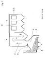
- Fig. 1 shows a longitudinal section of a schematically shown Waste incineration plant, which essentially consists of a water-cooled Combustion grate 1, a combustion chamber 2 arranged above it and one downstream boiler 3 with vertical empty trains 4 and a horizontal one Bundle train 5 exists.
- the firing material 6, in this case garbage, is placed on the grate 1 abandoned and burned with the supply of primary air 7 and 8 secondary air.
- the resulting smoke gases 9 enter the boiler 3 and flow under them Dissipation of heat through the vertical empty trains 4 and the horizontal Bundle train 5 of the boiler 3 and are then not shown Flue gas cleaning system supplied. To this extent, such systems are known.
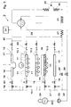
- Fig. 2 shows a schematic representation of the cooling system of the water-cooled grate 1 with downstream boiler 3 in a first Embodiment variant of the invention.
- the grate 1 consists essentially of several rows (10.1, 10.2, 10.3 ...) of side by side Grate covering units 11.
- Fig. 2 are examples of a thermally highly stressed Row 10.1 and two low thermal loads rows 10.2 and 10.3 are shown, the row 10.2 is a fixed grating unit row and the row 10.3 is to represent a moving row of grate pads and the two rows 10.2 and 10.3 are connected by a flexible connecting line 38.
- the Grate covering units 11 can be narrow grate bars or wider grate plates. Adjacent rows overlap like tiles. It can be lengthways of the grate alternately moving and fixed rows may be arranged or all rows can be moved.
- the grate 1 also has side walls 12 on.
- cooling channels 14 for Application of cooling water 15 is arranged, which in Fig. 2 only in the Grate covering unit row 10.3 is shown schematically.
- the cooling channels 14 are preferably coils cast into the grate covering units 11, which are connected to supply lines 16 and discharge lines 17, the Lines 16, 17 are thin tubes, each of which has an expansion circle 18 can have.
- the cooling channels 14 are comparatively small Inner diameter, for example 14 mm. This is designed in such a way that there is no separation of water and steam in the pipes.
- the Inner diameter of the feed lines 16 is much smaller than that Inner diameter of the cooling channels 14, for example 8 mm.
- the Inner diameter of the discharge lines 17 is due to the Vapor phase slightly larger than that of supply lines 16, but still much smaller than the diameter of the cooling channels 14 in the Grate covering units 11.
- each supply line 16 are a three-way valve 19 and at least one Pressure drop point 20 installed.
- these pressure drop points are 20 throttle valves.
- the supply lines 16 all branch off from a line 21, which in turn branches off from the feed water line 22, in which boiler feed water 23 from Feed water tank 24 via the feed water pump 25 and that Feed water control valve 26 via the economizer 27 in the drum 28 of the Boiler 3 is passed.
- the branching of line 21 from line 22 takes place after the feed water pump 25 and before the feed water control valve 26.
- the discharge lines 17 of the cooling systems each have check valves 29 and open into a collecting line 30 which connects to the drum 28 of the boiler 3 connected.
- the drum 28 is still with an evaporator 31 and a superheater 32 with a water injection 33, which via a Injector 36 is regulated in connection.
- the cooling system of the grate consists of several connected in parallel Subsystems.
- a subsystem for cooling is shown by way of example in FIG. 2 of the side walls 12, a subsystem for the cooling of a row of grating units 10.1 in the thermally highly stressed part of the grate 1, a subsystem for the Cooling of two grate lining unit rows 10.2 and 10.3 in the thermally lower loaded part of the grate 1 and a subsystem for cooling the central beams 13.
- cooling water 15 is used, which is a partial stream of demineralized degassed feed water 23 for the operation of the boiler 3.
- This cooling water 15 fits the economizer 27, it is after the feed water pump 25 and before the feed water control valve 26 removed from the feed line 22 and flows via line 15 into the supply lines 16 of the parallel subsystems of the Cooling system.
- the grate cooling thus takes place parallel to the economiser operation. Because part of the Boiler feed water is used as cooling water 15, stands for grate cooling there is always enough water available, which is also perfect Quality and sufficient pressure.
- the supply and discharge of the cooling water 15 to the grate components to be cooled 11, 12, 13 takes place via lines 16 and 17, which pipes with very small Are diameters. Thanks to this small diameter, they are so flexible that the movement of the grate covering units or a partial grate, the z. B. +/- 350 mm may be involved without further ado.
- expansion circles 18 are provided in the lines 16, 17 to compensate for the movement or the thermal expansions.
- the lines 16, 17 can also be made without expansion circles 18 be formed, as in FIG. 2 in the partial cooling system of the central beam 13 is shown.
- throttle valve 20 causes a pressure drop, which at least 1 ⁇ 4 of the pressure drop between the outlet from the Feed water pump 25 and entry into the drum 28 is.
- the cooling water 15 is used for cooling the grate covering units 11 Side walls 12 and the central beam 13 at least up to close to the Saturated steam temperature warmed up. In the normal case, the cooling water 15 except for the Saturated steam temperature warmed so that part of the water 15 evaporates.
- the Cooling water can also be completely or to a large extent (steam content> 0.3) evaporate, d. H. cooling is based on the single-tube boiler principle.
- the heat from the rust components to be cooled is combined with the water or removed the water / steam mixture. Flows per subsystem of the cooling system very little cooling water 15, so all the sensible heat and part of it Evaporation heat is used. Therefore, the cooling channels 14, that is Cooling pipes only of a relatively small diameter.
- the cooling channels 14, that is Cooling pipes only of a relatively small diameter have the advantage that steam and water do not separate. Thanks to the always safe Water supply for cooling does not require the guarantee of emergency running properties, so that no expensive high-alloyed as rust material Cast steel can be used, but cheaper low-alloy material can be used.
- the heated cooling water or water / steam mixture is discharged on the outlet side the lines 17 into a collecting line 30 and from there into the drum 28 guided.
- the cooling takes place at a pressure and temperature level that is only slightly above that of the drum 28. The advantage is that the delivery of the dissipated amount of heat in the drum 28 is always possible.
- a TCA temperature control system measures the outlet temperature of the heated cooling medium in line 17.
- the corresponding signals are passed to the valve 20, which depends on the respective Temperature level controls the amount of cooling water to be supplied 15, d. H. at a high temperature value, the valve 20 will open further, so that more Cooling water 15 is passed into the corresponding cooling channels 14 than at one lower temperature. In this way, the cooling can be optimized in which case slightly superheated steam is generated (single-tube boiler principle).
- Fig. 3 shows a schematic representation of the cooling system water-cooled grate with downstream boiler in a second Embodiment variant of the invention. This differs from that in FIG. 1 illustrated and described above only in that as Pressure drops 20 orifices can be used. This is compared to that first embodiment variant cheaper. Thin tubes or manually operated needle valves can be used.
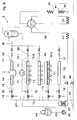
- Fig. 4 shows a third embodiment of the invention analogous to Fig. 2, in which as a consumer of the heated cooling water 15 or the water / steam mixture not the boiler 28, but the feed water tank 24 functions.
- the customer is the Air preheater (economiser 27) or, as shown in dashed lines, one District heating supply device 34.
- the vapor pressure which is set can be lower than the drum pressure, which is advantageously a deeper one Rust surface temperature.
- the manifold 30 in a steam separator 35th lead so that the water / steam mixture gets into the steam separator, the separated steam then into the drum 28 of the boiler 3 lead and the remaining saturated water into the feed water tank 24 attributable, thereby additionally the cooling water 15 via a Heat exchanger 37 can be preheated.
- the water supply line 16 to a moving Grid lining unit row 10.3 leads, this via a flexible connecting line 38 is connected to a fixed grating unit row 10.2 and the Discharge line 17 from the fixed grate lining unit row 10.2 to Bus line 30 leads.
- the discharge line 17 can have a larger diameter, since it does not have to be flexible and that in it contained water / steam mixture creates only a small pressure drop.
Landscapes
- Engineering & Computer Science (AREA)
- Mechanical Engineering (AREA)
- General Engineering & Computer Science (AREA)
- Chemical & Material Sciences (AREA)
- Combustion & Propulsion (AREA)
- Incineration Of Waste (AREA)
- Furnace Details (AREA)
- Preliminary Treatment Of Fibers (AREA)
- Waste-Gas Treatment And Other Accessory Devices For Furnaces (AREA)
- Baking, Grill, Roasting (AREA)
- Fertilizers (AREA)
- Control Of Steam Boilers And Waste-Gas Boilers (AREA)
Applications Claiming Priority (2)
| Application Number | Priority Date | Filing Date | Title |
|---|---|---|---|
| DE19943665A DE19943665B4 (de) | 1999-09-13 | 1999-09-13 | Verfahren zur Kühlung eines Rostes für einen Feuerraum mittels Wasser sowie Rost zur Verbrennung von Feststoffen |
| DE19943665 | 1999-09-13 |
Publications (2)
| Publication Number | Publication Date |
|---|---|
| EP1085264A1 true EP1085264A1 (fr) | 2001-03-21 |
| EP1085264B1 EP1085264B1 (fr) | 2005-11-16 |
Family
ID=7921746
Family Applications (1)
| Application Number | Title | Priority Date | Filing Date |
|---|---|---|---|
| EP00810789A Expired - Lifetime EP1085264B1 (fr) | 1999-09-13 | 2000-09-01 | Procédé et dispositif pour le refroidissement par eau d'une grille de combustion |
Country Status (7)
| Country | Link |
|---|---|
| EP (1) | EP1085264B1 (fr) |
| JP (1) | JP2001124324A (fr) |
| KR (1) | KR100659956B1 (fr) |
| AT (1) | ATE310209T1 (fr) |
| DE (2) | DE19943665B4 (fr) |
| NO (1) | NO323854B1 (fr) |
| TW (1) | TW550362B (fr) |
Cited By (3)
| Publication number | Priority date | Publication date | Assignee | Title |
|---|---|---|---|---|
| CN101956984A (zh) * | 2010-11-04 | 2011-01-26 | 无锡太湖锅炉有限公司 | 一种单锅筒三通道链条锅炉 |
| DE102014008858A1 (de) | 2014-06-16 | 2015-12-17 | Joachim Kümmel | Verfahren zur Verbrennung von Abfall und Biomassen auf einem Flossenwand-Stufenrost sowie Vorrichtung zur Durchführung des Verfahrens |
| CN106195987A (zh) * | 2016-08-30 | 2016-12-07 | 江苏太湖锅炉股份有限公司 | 高灰分低温余热锅炉 |
Families Citing this family (4)
| Publication number | Priority date | Publication date | Assignee | Title |
|---|---|---|---|---|
| CN101310146B (zh) * | 2005-07-19 | 2010-08-18 | 塞拉米克燃料电池有限公司 | 蒸汽发生器 |
| JP5530007B2 (ja) * | 2013-07-24 | 2014-06-25 | 有限会社春日サービス | 固形燃料焚きボイラー燃焼装置及び産業廃棄物用の焼却炉装置 |
| CN105180143A (zh) * | 2015-08-12 | 2015-12-23 | 神华集团有限责任公司 | 一种用于循环流化床锅炉的乏汽回收设备及系统 |
| CN115751347B (zh) * | 2023-02-13 | 2023-04-07 | 光大环保技术装备(常州)有限公司 | 水冷炉排温度和流量检测系统及其检测方法 |
Citations (11)
| Publication number | Priority date | Publication date | Assignee | Title |
|---|---|---|---|---|
| FR739654A (fr) * | 1900-01-01 | |||
| DE493854C (de) * | 1930-03-14 | Babcock & Wilcox Dampfkessel W | Aus wassergekuehlten, sich kreuzenden Rohren bestehender Rost fuer Kohlenstaubfeuerungen | |
| DE561099C (de) * | 1929-08-11 | 1932-10-10 | Willi Thieme | Feuerungsrost aus laengsliegenden Roststaeben, die zur Foerderung des Brennstoffes in Gruppen herausgezogen und in Richtung auf die Feuerbruecke zurueckgeschoben werden |
| DE808263C (de) * | 1948-10-02 | 1951-07-12 | Steinmueller Gmbh L & C | Selbstfoerdernder, wassergekuehlter Planrost |
| US3599609A (en) * | 1969-09-05 | 1971-08-17 | Charles L Wellons | Oven for burning waste wood products |
| WO1994018502A1 (fr) * | 1993-02-12 | 1994-08-18 | Ostlie L David | Grille de refroidissement a tubes empiles et systeme thermique d'une centrale electrique |
| DE4400992C1 (de) | 1994-01-14 | 1995-05-11 | Noell Abfall & Energietech | Roststab und Rost mit Kühleinrichtung |
| EP0621449B1 (fr) | 1993-04-20 | 1995-08-09 | Doikos Investments Ltd | Procédé pour la combustion de déchets sur une grille de combustion ainsi qu'une grille de combustion pour la mise en oeuvre du procédé et barreau pour la fabrication d'une telle grille |
| DE19508899A1 (de) | 1995-03-11 | 1996-09-12 | Erk Eckrohrkessel | Wassergekühlter Schrägrost mit mechanischem Brennstoff- und Aschetransport |
| WO1996029544A1 (fr) * | 1995-03-23 | 1996-09-26 | Theodor Koch | Grille de combustion et procede d'optimisation du fonctionnement d'une grille de combustion |
| EP0757206A2 (fr) | 1995-08-02 | 1997-02-05 | Asea Brown Boveri Ag | Grille pour un foyer |
Family Cites Families (4)
| Publication number | Priority date | Publication date | Assignee | Title |
|---|---|---|---|---|
| DE3207433A1 (de) * | 1982-03-02 | 1983-09-08 | Rudolf Dr. 6800 Mannheim Wieser | Wasserrohrkessel mit rostfeuerung |
| JPH0231523Y2 (fr) * | 1985-04-23 | 1990-08-27 | ||
| JPH07180824A (ja) * | 1993-12-22 | 1995-07-18 | Mitsubishi Heavy Ind Ltd | ストーカ |
| JPH116613A (ja) * | 1997-06-17 | 1999-01-12 | Kubota Corp | 火格子冷却機構 |
-
1999
- 1999-09-13 DE DE19943665A patent/DE19943665B4/de not_active Expired - Lifetime
-
2000
- 2000-09-01 AT AT00810789T patent/ATE310209T1/de active
- 2000-09-01 DE DE50011615T patent/DE50011615D1/de not_active Expired - Lifetime
- 2000-09-01 EP EP00810789A patent/EP1085264B1/fr not_active Expired - Lifetime
- 2000-09-12 NO NO20004547A patent/NO323854B1/no not_active IP Right Cessation
- 2000-09-13 JP JP2000278824A patent/JP2001124324A/ja active Pending
- 2000-09-14 KR KR1020000054077A patent/KR100659956B1/ko not_active Expired - Lifetime
- 2000-09-25 TW TW089118714A patent/TW550362B/zh not_active IP Right Cessation
Patent Citations (11)
| Publication number | Priority date | Publication date | Assignee | Title |
|---|---|---|---|---|
| FR739654A (fr) * | 1900-01-01 | |||
| DE493854C (de) * | 1930-03-14 | Babcock & Wilcox Dampfkessel W | Aus wassergekuehlten, sich kreuzenden Rohren bestehender Rost fuer Kohlenstaubfeuerungen | |
| DE561099C (de) * | 1929-08-11 | 1932-10-10 | Willi Thieme | Feuerungsrost aus laengsliegenden Roststaeben, die zur Foerderung des Brennstoffes in Gruppen herausgezogen und in Richtung auf die Feuerbruecke zurueckgeschoben werden |
| DE808263C (de) * | 1948-10-02 | 1951-07-12 | Steinmueller Gmbh L & C | Selbstfoerdernder, wassergekuehlter Planrost |
| US3599609A (en) * | 1969-09-05 | 1971-08-17 | Charles L Wellons | Oven for burning waste wood products |
| WO1994018502A1 (fr) * | 1993-02-12 | 1994-08-18 | Ostlie L David | Grille de refroidissement a tubes empiles et systeme thermique d'une centrale electrique |
| EP0621449B1 (fr) | 1993-04-20 | 1995-08-09 | Doikos Investments Ltd | Procédé pour la combustion de déchets sur une grille de combustion ainsi qu'une grille de combustion pour la mise en oeuvre du procédé et barreau pour la fabrication d'une telle grille |
| DE4400992C1 (de) | 1994-01-14 | 1995-05-11 | Noell Abfall & Energietech | Roststab und Rost mit Kühleinrichtung |
| DE19508899A1 (de) | 1995-03-11 | 1996-09-12 | Erk Eckrohrkessel | Wassergekühlter Schrägrost mit mechanischem Brennstoff- und Aschetransport |
| WO1996029544A1 (fr) * | 1995-03-23 | 1996-09-26 | Theodor Koch | Grille de combustion et procede d'optimisation du fonctionnement d'une grille de combustion |
| EP0757206A2 (fr) | 1995-08-02 | 1997-02-05 | Asea Brown Boveri Ag | Grille pour un foyer |
Non-Patent Citations (1)
| Title |
|---|
| "MODERN GERMAN BOILER PRACTICE", INFO AUSGABE DER WASSERROHRKESSEL VERBAND, XX, XX, 1 December 1954 (1954-12-01), XX, pages 20 - 22, XP002907570 |
Cited By (3)
| Publication number | Priority date | Publication date | Assignee | Title |
|---|---|---|---|---|
| CN101956984A (zh) * | 2010-11-04 | 2011-01-26 | 无锡太湖锅炉有限公司 | 一种单锅筒三通道链条锅炉 |
| DE102014008858A1 (de) | 2014-06-16 | 2015-12-17 | Joachim Kümmel | Verfahren zur Verbrennung von Abfall und Biomassen auf einem Flossenwand-Stufenrost sowie Vorrichtung zur Durchführung des Verfahrens |
| CN106195987A (zh) * | 2016-08-30 | 2016-12-07 | 江苏太湖锅炉股份有限公司 | 高灰分低温余热锅炉 |
Also Published As
| Publication number | Publication date |
|---|---|
| NO20004547D0 (no) | 2000-09-12 |
| NO20004547L (no) | 2001-03-14 |
| DE19943665B4 (de) | 2006-04-13 |
| EP1085264B1 (fr) | 2005-11-16 |
| DE19943665A1 (de) | 2001-03-15 |
| DE50011615D1 (de) | 2005-12-22 |
| KR20010030387A (ko) | 2001-04-16 |
| JP2001124324A (ja) | 2001-05-11 |
| ATE310209T1 (de) | 2005-12-15 |
| TW550362B (en) | 2003-09-01 |
| NO323854B1 (no) | 2007-07-16 |
| KR100659956B1 (ko) | 2006-12-22 |
Similar Documents
| Publication | Publication Date | Title |
|---|---|---|
| DE3147864C2 (de) | Abwärmekessel für die Kühlung von Synthesegas | |
| EP0815396B1 (fr) | Grille de combustion et procede d'optimisation du fonctionnement d'une grille de combustion | |
| DE2819185A1 (de) | Fliessbett-verbrennungsvorrichtung | |
| DE102005009202A1 (de) | Blockwärmetauscher für staubhaltige Rauchgase | |
| EP0713056B1 (fr) | Barreau de grille avec dispositif de refroidissement | |
| EP1701090A1 (fr) | Générateur de vapeur à construction horizontale | |
| DE19943665B4 (de) | Verfahren zur Kühlung eines Rostes für einen Feuerraum mittels Wasser sowie Rost zur Verbrennung von Feststoffen | |
| DD291803A5 (de) | Anlage und verfahren zur regelung der temperatur von zwischenueberhitzungsdampf bei dampfkesseln mit zirkulierender wirbelschicht | |
| DD218661A5 (de) | Verfahren und vorrichtung zum wiederaufheizen entschwefelter rauchgase | |
| EP3339733A1 (fr) | Installation de récupération de chaleur | |
| DE3050901C2 (de) | Verbrennungseinrichtung mit einer ein Fließbett enthaltenden Brennkammer | |
| EP1512905A1 (fr) | Générateur de vapeur à passage unique et méthode pour faire fonctionner ledit générateur de vapeur à passage unique | |
| EP0663561A1 (fr) | Générateur de vapeur | |
| DE3027517A1 (de) | Wirbelschichtfeuerung | |
| DE2039180A1 (de) | Mit einem fluidisierten Brennstoffbett betriebener Dampfkessel | |
| DE4300192A1 (de) | Verfahren zum Betrieb von mindestens zwei miteinander verknüpften Abhitzeprozessen und Dampferzeugungsanlage zur Durchführung des Verfahrens | |
| DE202013104381U1 (de) | Wirbelschichtfeuerung | |
| DE557596C (de) | Dampferzeuger mit Brennraum | |
| EP1959195B1 (fr) | Procédé de réglage de la température de gaz de fumées | |
| EP1398564A1 (fr) | Procédé pour faire fonctionner un générateur de vapeur à construcion horizontale, et générateur de vapeur pour mettre en oeuvre ledit procédé | |
| DE2905628A1 (de) | Kuehlanlage fuer einen hochofen | |
| DE465425C (de) | Dampfkessel, insbesondere fuer Kohlenstaubfeuerung, mit mittelbarer Erzeugung des Betriebsdampfs | |
| DE1401390A1 (de) | Abhitzekessel mit konstanter Last hinter intermittierend arbeitenden Huettenoefen,vorzugsweise hinter Stahlkonverten | |
| DE1501380A1 (de) | Verfahren und Vorrichtung zum Waermeaustausch zwischen Gasen,Daempfen,Fluessigkeiten und/oder festen Stoffen einerseits und festen oder fluessigen Waermetraegern andererseits | |
| EP2564117B1 (fr) | Générateur de vapeur |
Legal Events
| Date | Code | Title | Description |
|---|---|---|---|
| PUAI | Public reference made under article 153(3) epc to a published international application that has entered the european phase |
Free format text: ORIGINAL CODE: 0009012 |
|
| AK | Designated contracting states |
Kind code of ref document: A1 Designated state(s): AT BE CH CY DE DK ES FI FR GB GR IE IT LI LU MC NL PT SE |
|
| AX | Request for extension of the european patent |
Free format text: AL;LT;LV;MK;RO;SI |
|
| 17P | Request for examination filed |
Effective date: 20010912 |
|
| AKX | Designation fees paid |
Free format text: AT BE CH CY DE DK ES FI FR GB GR IE IT LI LU MC NL PT SE |
|
| RAP1 | Party data changed (applicant data changed or rights of an application transferred) |
Owner name: ALSTOM |
|
| TPAD | Observations filed by third parties |
Free format text: ORIGINAL CODE: EPIDOS TIPA |
|
| RAP1 | Party data changed (applicant data changed or rights of an application transferred) |
Owner name: ALSTOM (SWITZERLAND) LTD |
|
| RAP1 | Party data changed (applicant data changed or rights of an application transferred) |
Owner name: ALSTOM |
|
| 17Q | First examination report despatched |
Effective date: 20031006 |
|
| RAP1 | Party data changed (applicant data changed or rights of an application transferred) |
Owner name: MARTIN GMBH FUER UMWELT-UND ENERGIETECHNIK |
|
| GRAP | Despatch of communication of intention to grant a patent |
Free format text: ORIGINAL CODE: EPIDOSNIGR1 |
|
| GRAS | Grant fee paid |
Free format text: ORIGINAL CODE: EPIDOSNIGR3 |
|
| GRAA | (expected) grant |
Free format text: ORIGINAL CODE: 0009210 |
|
| AK | Designated contracting states |
Kind code of ref document: B1 Designated state(s): AT BE CH CY DE DK ES FI FR GB GR IE IT LI LU MC NL PT SE |
|
| PG25 | Lapsed in a contracting state [announced via postgrant information from national office to epo] |
Ref country code: GB Free format text: LAPSE BECAUSE OF FAILURE TO SUBMIT A TRANSLATION OF THE DESCRIPTION OR TO PAY THE FEE WITHIN THE PRESCRIBED TIME-LIMIT Effective date: 20051116 Ref country code: FI Free format text: LAPSE BECAUSE OF FAILURE TO SUBMIT A TRANSLATION OF THE DESCRIPTION OR TO PAY THE FEE WITHIN THE PRESCRIBED TIME-LIMIT Effective date: 20051116 Ref country code: IE Free format text: LAPSE BECAUSE OF FAILURE TO SUBMIT A TRANSLATION OF THE DESCRIPTION OR TO PAY THE FEE WITHIN THE PRESCRIBED TIME-LIMIT Effective date: 20051116 |
|
| REG | Reference to a national code |
Ref country code: GB Ref legal event code: FG4D Free format text: NOT ENGLISH |
|
| REG | Reference to a national code |
Ref country code: CH Ref legal event code: EP |
|
| REG | Reference to a national code |
Ref country code: IE Ref legal event code: FG4D Free format text: LANGUAGE OF EP DOCUMENT: GERMAN |
|
| REF | Corresponds to: |
Ref document number: 50011615 Country of ref document: DE Date of ref document: 20051222 Kind code of ref document: P |
|
| REG | Reference to a national code |
Ref country code: CH Ref legal event code: NV Representative=s name: MICHELI & CIE INGENIEURS-CONSEILS |
|
| PG25 | Lapsed in a contracting state [announced via postgrant information from national office to epo] |
Ref country code: DK Free format text: LAPSE BECAUSE OF FAILURE TO SUBMIT A TRANSLATION OF THE DESCRIPTION OR TO PAY THE FEE WITHIN THE PRESCRIBED TIME-LIMIT Effective date: 20060216 Ref country code: GR Free format text: LAPSE BECAUSE OF FAILURE TO SUBMIT A TRANSLATION OF THE DESCRIPTION OR TO PAY THE FEE WITHIN THE PRESCRIBED TIME-LIMIT Effective date: 20060216 |
|
| PG25 | Lapsed in a contracting state [announced via postgrant information from national office to epo] |
Ref country code: ES Free format text: LAPSE BECAUSE OF FAILURE TO SUBMIT A TRANSLATION OF THE DESCRIPTION OR TO PAY THE FEE WITHIN THE PRESCRIBED TIME-LIMIT Effective date: 20060227 |
|
| REG | Reference to a national code |
Ref country code: SE Ref legal event code: TRGR |
|
| PG25 | Lapsed in a contracting state [announced via postgrant information from national office to epo] |
Ref country code: PT Free format text: LAPSE BECAUSE OF FAILURE TO SUBMIT A TRANSLATION OF THE DESCRIPTION OR TO PAY THE FEE WITHIN THE PRESCRIBED TIME-LIMIT Effective date: 20060417 |
|
| GBV | Gb: ep patent (uk) treated as always having been void in accordance with gb section 77(7)/1977 [no translation filed] |
Effective date: 20051116 |
|
| REG | Reference to a national code |
Ref country code: IE Ref legal event code: FD4D |
|
| ET | Fr: translation filed | ||
| PLBE | No opposition filed within time limit |
Free format text: ORIGINAL CODE: 0009261 |
|
| STAA | Information on the status of an ep patent application or granted ep patent |
Free format text: STATUS: NO OPPOSITION FILED WITHIN TIME LIMIT |
|
| PG25 | Lapsed in a contracting state [announced via postgrant information from national office to epo] |
Ref country code: MC Free format text: LAPSE BECAUSE OF NON-PAYMENT OF DUE FEES Effective date: 20060930 |
|
| 26N | No opposition filed |
Effective date: 20060817 |
|
| PG25 | Lapsed in a contracting state [announced via postgrant information from national office to epo] |
Ref country code: LU Free format text: LAPSE BECAUSE OF NON-PAYMENT OF DUE FEES Effective date: 20060901 |
|
| PG25 | Lapsed in a contracting state [announced via postgrant information from national office to epo] |
Ref country code: CY Free format text: LAPSE BECAUSE OF FAILURE TO SUBMIT A TRANSLATION OF THE DESCRIPTION OR TO PAY THE FEE WITHIN THE PRESCRIBED TIME-LIMIT Effective date: 20051116 |
|
| REG | Reference to a national code |
Ref country code: FR Ref legal event code: PLFP Year of fee payment: 17 |
|
| REG | Reference to a national code |
Ref country code: FR Ref legal event code: PLFP Year of fee payment: 18 |
|
| REG | Reference to a national code |
Ref country code: FR Ref legal event code: PLFP Year of fee payment: 19 |
|
| PGFP | Annual fee paid to national office [announced via postgrant information from national office to epo] |
Ref country code: NL Payment date: 20190918 Year of fee payment: 20 Ref country code: FR Payment date: 20190925 Year of fee payment: 20 Ref country code: IT Payment date: 20190925 Year of fee payment: 20 Ref country code: SE Payment date: 20190918 Year of fee payment: 20 Ref country code: DE Payment date: 20190918 Year of fee payment: 20 |
|
| PGFP | Annual fee paid to national office [announced via postgrant information from national office to epo] |
Ref country code: BE Payment date: 20190918 Year of fee payment: 20 |
|
| PGFP | Annual fee paid to national office [announced via postgrant information from national office to epo] |
Ref country code: AT Payment date: 20190919 Year of fee payment: 20 |
|
| PGFP | Annual fee paid to national office [announced via postgrant information from national office to epo] |
Ref country code: CH Payment date: 20190919 Year of fee payment: 20 |
|
| REG | Reference to a national code |
Ref country code: DE Ref legal event code: R071 Ref document number: 50011615 Country of ref document: DE |
|
| REG | Reference to a national code |
Ref country code: NL Ref legal event code: MK Effective date: 20200831 |
|
| REG | Reference to a national code |
Ref country code: CH Ref legal event code: PL |
|
| REG | Reference to a national code |
Ref country code: BE Ref legal event code: MK Effective date: 20200901 Ref country code: AT Ref legal event code: MK07 Ref document number: 310209 Country of ref document: AT Kind code of ref document: T Effective date: 20200901 |