EP1085384B1 - Elektronische Chronographuhr - Google Patents
Elektronische Chronographuhr Download PDFInfo
- Publication number
- EP1085384B1 EP1085384B1 EP19990118374 EP99118374A EP1085384B1 EP 1085384 B1 EP1085384 B1 EP 1085384B1 EP 19990118374 EP19990118374 EP 19990118374 EP 99118374 A EP99118374 A EP 99118374A EP 1085384 B1 EP1085384 B1 EP 1085384B1
- Authority
- EP
- European Patent Office
- Prior art keywords
- hand
- watch
- central
- small
- seconds
- Prior art date
- Legal status (The legal status is an assumption and is not a legal conclusion. Google has not performed a legal analysis and makes no representation as to the accuracy of the status listed.)
- Expired - Lifetime
Links
- 230000006870 function Effects 0.000 description 12
- 238000010586 diagram Methods 0.000 description 3
- 230000009977 dual effect Effects 0.000 description 2
- 240000008042 Zea mays Species 0.000 description 1
- 238000012986 modification Methods 0.000 description 1
- 230000004048 modification Effects 0.000 description 1
- 230000007935 neutral effect Effects 0.000 description 1
- 239000010453 quartz Substances 0.000 description 1
- 238000007493 shaping process Methods 0.000 description 1
- VYPSYNLAJGMNEJ-UHFFFAOYSA-N silicon dioxide Inorganic materials O=[Si]=O VYPSYNLAJGMNEJ-UHFFFAOYSA-N 0.000 description 1
- 230000001960 triggered effect Effects 0.000 description 1
Images


Classifications
-
- G—PHYSICS
- G04—HOROLOGY
- G04C—ELECTROMECHANICAL CLOCKS OR WATCHES
- G04C3/00—Electromechanical clocks or watches independent of other time-pieces and in which the movement is maintained by electric means
- G04C3/14—Electromechanical clocks or watches independent of other time-pieces and in which the movement is maintained by electric means incorporating a stepping motor
- G04C3/146—Electromechanical clocks or watches independent of other time-pieces and in which the movement is maintained by electric means incorporating a stepping motor incorporating two or more stepping motors or rotors
-
- G—PHYSICS
- G04—HOROLOGY
- G04F—TIME-INTERVAL MEASURING
- G04F8/00—Apparatus for measuring unknown time intervals by electromechanical means
Definitions
- the present invention relates to electronic chronograph watches.
- the hour is indicated by an hour hand and a minute hand rotating around the center of the watch and by an off-center seconds hand, called a small second, generally placed at six o'clock.
- the indication of a timed time is made by means of a large seconds hand concentric to the hour and minute hands indicating the current time and two other small off-center hands located at ten o'clock and two o'clock, which show the hours, up to 12 or 24, and minutes, usually up to thirty.
- Such a watch is described, for example, in EP 0 617 346 .
- the seconds and minutes that are timed are indicated by two large concentric hands at the hour and minute hands for displaying the current time and two small hands at ten o'clock. at two o'clock for the indication of hours and tenths or twentieths of a second.
- the watch operates in chronograph mode
- the user no longer has the indication of the seconds of the current time, which can be embarrassing for him, especially when the time is long and can reach several hours .
- this user wants to reset his watch on time, to the nearest second while using the chronograph function, he can not.
- the present invention aims to overcome these disadvantages of existing watches and this goal is achieved through the features of the chronograph watch defined in claim 1.
- the chronograph watch 1 comprises a dial 2 in front of which can be moved, for the indication of the current time, a hand of the hours 3 and a hand of central and coaxial minutes 4, and a small hand seconds off-center and at six o'clock.
- this chronograph watch also comprises a central seconds hand 5, coaxial and superimposed on the hands of hours 3 and 4 minutes.
- the watch of the figure 1 also includes a small hand 7 hours timed off center at ten o'clock, a central hand 8 minutes timed part of the superposition of the other central needles 3, 4 and 5, and a needle 9 tenths of seconds timed off center at two o'clock.
- the timed seconds are indicated in this watch by the central hand 5 which thus fulfills the dual role of selectively indicating the seconds of the current time and the seconds timed.
- the watch of the figure 1 also comprises a ring 10 with three positions, T1, T2 and T3, respectively corresponding in the order to neutral, the correction of the time zone and the time setting, the latter position also stopping the indication of the current time.
- Two pushers P1 and P2 are provided for controlling the timing functions, the pushbutton P1 controlling the start and stop of the timing and the pusher P2 reset.
- Other commands known per se, can be assigned to pushbuttons P1 and P2.
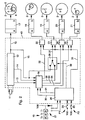
- FIG 2 represents a very simplified diagram of the chronograph watch that has just been described, this diagram representing only the elements and functions of its electrical circuit necessary for the understanding of the invention.
- a quartz oscillator vibrating for example at 32768 Hz and of which only the resonator 11 is represented on the figure 2 provides the time base of the watch to a frequency divider 12. This generates on a line 13 clock pulses for controlling the electronic functions of the watch.
- the divider 12 also provides pulses of tenths of a second on a line 14 and pulses of a second on a line 15. These lines are connected to a unit 16 for managing the timing functions.
- Line 15 transmits the second pulses also to a drive unit 17. This is mechanically coupled to a gear train (not shown) to permanently drive the needles 3, 4 and 6 for the indication of the current time.
- each unit comprising, as known per se, a driving circuit indicated by "a” and an engine indicated by "b".
- the drive unit 18 drives the needle 9 tenths of seconds, the unit 19, the central hand 5 of the seconds, the unit 20, the minute hand 8 and the unit 21, the hour hand 7 hours.
- the driving units 18 to 21 are associated with respective counters 22 to 25 whose states reflect at each instant, the angular positions of the needles to which they correspond.
- Each counter is set to zero at the initialization of the associated twelve-hour hand and counts each driving pulse transmitted by the timing management unit 16.
- the counter 22 can count to 10 (tenth of second), the counters 23 and 24 up to sixty and the counter 25 up to twelve.
- An input management unit 26 provides the shaping and distribution of the control signals respectively provided by a switch 27 associated with the ring gear 10 and by switches 28 and 29 respectively associated with the pushers P1 and P2.
- a command made by these members 27 to 29 returns, in a manner known per se, to apply to the management unit 26 the potential of one of the terminals (here Vdd) of a power source (not shown) such a battery incorporated in the watch 1.
- the input management unit 26 Depending on the actions on the pushbuttons P1 and P2, the input management unit 26 generates a timing start / stop command signal on a line 30 and a reset command signal on a line 31, the lines 30 and 31 being connected to the timing management unit 16.
- control pulses for the counters 22, 24 and 25 respectively on lines 32 to 34 can also be directly positioned by the input management unit 26 through a control line 35.
- a switching unit 36 is connected by a control line 37 to the counter 23 responsible for cooperating with the power unit 19 of the central seconds hand 5 indicating seconds.
- This switching unit 36 is connected on the one hand directly to the divider 12 by the line 15 on which the pulses of seconds of the current time pass, and on the other hand to the management unit 16 by a line 38 on which transits the timed second pulses.
- This switching unit 36 receives inversion commands from the input management unit 26 via a line 39.
- the rotation of the second hand can selectively be subordinated to the second pulses of the current time (line 15) or to the second pulses of the timed time. (line 38). That's why, right on the figure 2 , the needle 5 is shown in dashed lines on two representations of the dial 2.
- the watch rotates the needles 3, 4 and 6 by the drive unit 17 controlled by the pulses of second passing on the line 15.
- the needle 5 rotates in synchronism with the needle 6, 1 switching unit connecting this line 15 to the line 37 to control the drive unit 19. The user thus has a good readability of the second of the current time through the needle 5.
- the input management unit 26 controls the inversion of the switching unit 36 by the line 39 and the timing management unit 16 sends very quickly to the motor unit 19 pulses to return the needle 5 to the twelve o'clock position, if it is not already there and this at a speed sufficient not to distort the accuracy of time timed.
- the unit 16 applies the appropriate control signals to the lines 33, 34 and 37 so that through the counters 24, 25 and 23 and the drive units 20, 21 and 19 respectively, the needles 7, 8 and 5 respectively display the timed time.
- the counter 22 receives pulses of a tenth of a second but the drive unit 18 remains inactive and the needle 9 still.
- a new pressure on the pusher P1 stops the timing, without the position of the switching unit 36 is changed.
- the needles 5, 7 and 8 stop, while the motor unit 18 is activated by the timing management unit 16, so that the needle 9 advances to the angular position corresponding to the number of tenths of a second counted at moment of stopping timing.
- the input management unit 26 controls the inversion of the switching unit 36 and the timing management unit 16 sends pulses to the counter 23 and to the motor unit 19 so that the needle 5 quickly reaches the angular position that at this moment the second hand 6.
- the number of angular steps of this catch can be calculated by subtraction modulo 60 of the contents of the seconds counter (not shown) of the needle 6 by the content of the counter 23. This function is programmed in the microcontroller 40.
- the needle 6 continued to indicate the seconds of the current time. Therefore, the user continues to have information about the second of the current time, while the timing function is running.
- the embodiment shown on the figures 3 and 4 differs from that of figures 1 and 2 in that the display functions of the hands 7 and 8 are replaced by those of respective needles 7A and 8A, the first of which, 7A, indicates the minutes timed for example over 30 minutes and the second, 8A, the timed seconds.
- the programming of the microcontroller must of course be adapted accordingly.
- the needle 5 retains its dual role of displaying the second of the current time in phase with the seconds hand 6 to ensure good readability during walking in current time and display the second timed in timing step, the needle 5 then being superimposed on the needle 8A not to disturb a good reading of the second timed. During the execution of this function, the needle 6 continues to display the second of the current time.
- the timing function is triggered by an action on the pusher P1
- the needle 5 is superimposed in rapid traverse on the needle 8A.
- the display of the timed time is then ensured by the minute indicating needle 7A, the tenths of seconds indication needle 9 and superimposed by the seconds display needles 5 and 8A.
- the needle 5 is driven after tilting of the switching unit 36 under the control of the pulses of second timed transiting on the lines 38 and 37 and through the counter 23.
- a new pressure on the pushbutton P1 stops the timing and the hand 9 is positioned quickly to indicate the tenths of a second timed counted at the time of stopping timing.
- the needles 7A, 8A and 9 return to the starting position, while the needle 5 resumes at fast speed the position in phase with the needle 6 after tilting of the switching unit 36, the line 37 being connected again to the line 15 on which the pulses of seconds of the current time pass.
- this reinitialization can be carried out by means of particular and combined manipulations of the crown 10 and push-buttons P1 and P2, so as to bring back the small hand of seconds 6, the second hand at center 5 and in the first case ( figures 1 and 2 ) the chronograph minute hand 8 and in the second case the chronograph center seconds hand 8A at twelve o'clock.
- the needle 5 could act as a catch-up in the second embodiment of the invention.
Landscapes
- Physics & Mathematics (AREA)
- General Physics & Mathematics (AREA)
- Electromechanical Clocks (AREA)
- Measurement Of Unknown Time Intervals (AREA)
Claims (5)
- Elektronische Chronographenuhr umfassend :- einen zentralen Stundenzeiger (3), einen zentralen Minutenzeiger (4) und einen kleinen exzentrisch angeordneten Sekundenzeiger (6) zum ununterbrochenen Anzeigen der aktuellen Uhrzeit,- Chronographenzeiger (7, 8, 9; 7a, 8a, 9) zum Anzeigen einer chronometrierten Zeit, wenn die Uhr in einem Chronographenmodus betrieben wird,- Motoreinheiten (17 bis 21) zum Antreiben der Zeiger und- Generatormittel (40), welche manuellen Steuermitteln (P1, P2, 10, 27, 28, 29) gehorchen, um Steuerimpulse an die Motoreinheiten anzulegen,dadurch gekennzeichnet, dass sie ferner einen ersten zentralen Sekundenzeiger (5) umfasst, der von einer eigenen Motoreinheit (19) angetrieben wird, und dass die Generatormittel (40) Mittel (16, 36) umfassen, die geeignet ausgebildet sind, um an diese Motoreinheit (19) selektiv Steuerimpulse derart anzulegen, dass der zentrale Sekundenzeiger (5) die Sekunden der aktuellen Stunde in Phase mit dem kleinen exzentrisch angeordneten Sekundenzeiger (6) anzeigt, wenn die Uhr normal funktioniert, und die gemessenen Sekunden anzeigt, wenn die Uhr in Chronographenmodus funktioniert.
- Uhr nach Anspruch 1, dadurch gekennzeichnet, dass sie zur Anzeige einer gemessenen Zeit neben dem zentralen Sekundenzeiger (5) einen kleinen exzentrisch angeordneten Stundenzeiger (7), einen grossen zentralen Minutenzeiger (8) und einen kleinen exzentrisch angeordneten Zeiger für Zehntelsekunden (9) umfasst.
- Uhr nach Anspruch 1, dadurch gekennzeichnet, dass sie zur Anzeige einer gemessenen Zeit neben dem zentralen Sekundenzeiger (5) einen kleinen exzentrisch angeordneten Minutenzeiger (7a), einen kleinen exzentrisch angeordneten Zeiger (9) für Zehntelsekunden und einen zweiten zentralen Sekundenzeiger (8a) umfasst, der sich in Überlagerung mit dem ersten zentralen Sekundenzeiger (5) dreht, wenn die Uhr in einem Chronographenmodus betrieben wird.
- Uhr nach Anspruch 1, dadurch gekennzeichnet, dass die zentralen Stunden- und Minutenzeiger (3, 4) und der kleine exzentrisch angeordnete Sekundenzeiger (6) mechanisch miteinander gekoppelt sind und von einer gemeinsamen Motoreinheit (17) angetrieben sind.
- Uhr nach Anspruch 1, dadurch gekennzeichnet, dass die Chronographenzeiger (4. 8, 9; 7A, 8A, 9) wie der erste zentrale Sekundenzeiger (5) jeweils von einer Motoreinheit (18, 20, 21) angetrieben sind, die ihnen eigen ist.
Priority Applications (2)
| Application Number | Priority Date | Filing Date | Title |
|---|---|---|---|
| DE69939467T DE69939467D1 (de) | 1999-09-16 | 1999-09-16 | Elektronische Chronographuhr |
| EP19990118374 EP1085384B1 (de) | 1999-09-16 | 1999-09-16 | Elektronische Chronographuhr |
Applications Claiming Priority (1)
| Application Number | Priority Date | Filing Date | Title |
|---|---|---|---|
| EP19990118374 EP1085384B1 (de) | 1999-09-16 | 1999-09-16 | Elektronische Chronographuhr |
Publications (2)
| Publication Number | Publication Date |
|---|---|
| EP1085384A1 EP1085384A1 (de) | 2001-03-21 |
| EP1085384B1 true EP1085384B1 (de) | 2008-09-03 |
Family
ID=8239013
Family Applications (1)
| Application Number | Title | Priority Date | Filing Date |
|---|---|---|---|
| EP19990118374 Expired - Lifetime EP1085384B1 (de) | 1999-09-16 | 1999-09-16 | Elektronische Chronographuhr |
Country Status (2)
| Country | Link |
|---|---|
| EP (1) | EP1085384B1 (de) |
| DE (1) | DE69939467D1 (de) |
Families Citing this family (4)
| Publication number | Priority date | Publication date | Assignee | Title |
|---|---|---|---|---|
| JP2004020421A (ja) | 2002-06-18 | 2004-01-22 | Seiko Instruments Inc | 複数モータを備えたアナログクロノグラフ時計 |
| CH704948B1 (fr) * | 2004-02-17 | 2012-11-30 | Lvmh Swiss Mft Sa | Montre chronographe électromécanique à affichage rétrograde. |
| EP1939699B1 (de) | 2006-12-29 | 2012-05-30 | Montres Breguet S.A. | Multifunktionsvorrichtung zur koaxialen Korrektur |
| EP4105738B1 (de) * | 2021-06-14 | 2025-07-30 | ETA SA Manufacture Horlogère Suisse | Armbanduhr mit einer hilfsfunktion zur anzeige der sekunden |
Family Cites Families (3)
| Publication number | Priority date | Publication date | Assignee | Title |
|---|---|---|---|---|
| GB2166570B (en) * | 1984-09-26 | 1987-11-18 | Citizen Watch Co Ltd | Electronic timepiece with a chronograph system |
| CH686106B5 (fr) * | 1993-03-23 | 1996-07-15 | Ebauchesfabrik Eta Ag | Montre-chronographe avec indicateur de quantième. |
| DE69318575T2 (de) * | 1993-11-10 | 1998-11-26 | Citizen Watch Co., Ltd., Tokio/Tokyo | Weckeruhr |
-
1999
- 1999-09-16 DE DE69939467T patent/DE69939467D1/de not_active Expired - Lifetime
- 1999-09-16 EP EP19990118374 patent/EP1085384B1/de not_active Expired - Lifetime
Also Published As
| Publication number | Publication date |
|---|---|
| EP1085384A1 (de) | 2001-03-21 |
| DE69939467D1 (de) | 2008-10-16 |
Similar Documents
| Publication | Publication Date | Title |
|---|---|---|
| US6570823B1 (en) | Electronic chronograph watch | |
| EP0589353B1 (de) | Analoguhr mit der Möglichkeit zur Anzeige von Zusatzinformationen | |
| EP0589465B1 (de) | Analoguhr mit Warnungsmitteln für eine Betriebsartänderung | |
| EP1422583A1 (de) | Uhr mit numerischer Anzeige | |
| EP1625879B1 (de) | Elektronische Armbanduhr zum Erfassen des Golf-Scores | |
| EP0715233B1 (de) | Zeitmessgerät mit analoger Anzeige und Vorrichtung zur Auswahl von numerischen Informationen | |
| EP0059164B1 (de) | Uhr mit mehreren Funktionen | |
| CH704948B1 (fr) | Montre chronographe électromécanique à affichage rétrograde. | |
| EP0031077B1 (de) | Interaktive Vorrichtung zum Einführen von Daten in kleine Instrumente, insbesondere in Uhren | |
| EP0683441B1 (de) | Elektronische Uhr mit Minutenwiederholungsfunktion | |
| FR2490841A1 (fr) | Mouvement d'horlogerie electronique a dispositif de commutation indiquant la nature des modes de fonctionnement | |
| EP1085384B1 (de) | Elektronische Chronographuhr | |
| CH688461B5 (fr) | Pièce d'horlogerie à affichage analogique présentant au moins un mode d'affichage universel de l'heure. | |
| EP1807738B1 (de) | Elektronische uhr mit multifunktion und navigationshilfe, die speziell für weltraummissionen geeignet ist | |
| EP2021880A1 (de) | Verfahren zum wechseln einer zeitzone und uhr dafür | |
| EP1211579B1 (de) | Elektronische Chronographuhr mit analoger Anzeige | |
| FR2467429A1 (fr) | Piece d'horlogerie avec affichage de la seconde sur demande | |
| EP0202495B1 (de) | Zeitgeber | |
| EP0657792B1 (de) | Elektronischer analoger Chronograph mit Einholzeiger | |
| EP0027288B1 (de) | Elektronische Uhr mit Schrittmotor und Alarmschaltung | |
| EP0357633B1 (de) | Verfahren zum anzeigen von gespeicherten zeitinformationen auf einer uhrzeigerplatte und eine für ein solches verfahren ausgerüstete uhr | |
| WO2007098616A1 (fr) | Montre, notamment montre-bracelet | |
| CH685142B5 (fr) | Montre-chronographe comportant deux poussoirs à l'exclusion de toute tige-couronne. | |
| WO1990009623A1 (fr) | Dispositif d'affichage de dates, notamment pour piece d'horlogerie electronique | |
| WO2001096966A1 (fr) | Montre munie d'un indicateur de cycles hebdomadaires |
Legal Events
| Date | Code | Title | Description |
|---|---|---|---|
| PUAI | Public reference made under article 153(3) epc to a published international application that has entered the european phase |
Free format text: ORIGINAL CODE: 0009012 |
|
| AK | Designated contracting states |
Kind code of ref document: A1 Designated state(s): CH DE FR GB IT LI |
|
| AX | Request for extension of the european patent |
Free format text: AL;LT;LV;MK;RO;SI |
|
| 17P | Request for examination filed |
Effective date: 20010921 |
|
| AKX | Designation fees paid |
Free format text: CH DE FR GB IT LI |
|
| RAP1 | Party data changed (applicant data changed or rights of an application transferred) |
Owner name: ETA SA MANUFACTURE HORLOGERE SUISSE |
|
| GRAP | Despatch of communication of intention to grant a patent |
Free format text: ORIGINAL CODE: EPIDOSNIGR1 |
|
| GRAS | Grant fee paid |
Free format text: ORIGINAL CODE: EPIDOSNIGR3 |
|
| GRAA | (expected) grant |
Free format text: ORIGINAL CODE: 0009210 |
|
| AK | Designated contracting states |
Kind code of ref document: B1 Designated state(s): CH DE FR GB IT LI |
|
| REG | Reference to a national code |
Ref country code: GB Ref legal event code: FG4D Free format text: NOT ENGLISH |
|
| REG | Reference to a national code |
Ref country code: CH Ref legal event code: EP |
|
| REF | Corresponds to: |
Ref document number: 69939467 Country of ref document: DE Date of ref document: 20081016 Kind code of ref document: P |
|
| REG | Reference to a national code |
Ref country code: CH Ref legal event code: NV Representative=s name: ICB INGENIEURS CONSEILS EN BREVETS SA |
|
| PLBE | No opposition filed within time limit |
Free format text: ORIGINAL CODE: 0009261 |
|
| STAA | Information on the status of an ep patent application or granted ep patent |
Free format text: STATUS: NO OPPOSITION FILED WITHIN TIME LIMIT |
|
| 26N | No opposition filed |
Effective date: 20090604 |
|
| PG25 | Lapsed in a contracting state [announced via postgrant information from national office to epo] |
Ref country code: IT Free format text: LAPSE BECAUSE OF FAILURE TO SUBMIT A TRANSLATION OF THE DESCRIPTION OR TO PAY THE FEE WITHIN THE PRESCRIBED TIME-LIMIT Effective date: 20080903 |
|
| PGFP | Annual fee paid to national office [announced via postgrant information from national office to epo] |
Ref country code: GB Payment date: 20090827 Year of fee payment: 11 |
|
| GBPC | Gb: european patent ceased through non-payment of renewal fee |
Effective date: 20100916 |
|
| PG25 | Lapsed in a contracting state [announced via postgrant information from national office to epo] |
Ref country code: GB Free format text: LAPSE BECAUSE OF NON-PAYMENT OF DUE FEES Effective date: 20100916 |
|
| PGFP | Annual fee paid to national office [announced via postgrant information from national office to epo] |
Ref country code: DE Payment date: 20110902 Year of fee payment: 13 |
|
| PGFP | Annual fee paid to national office [announced via postgrant information from national office to epo] |
Ref country code: FR Payment date: 20111007 Year of fee payment: 13 |
|
| REG | Reference to a national code |
Ref country code: FR Ref legal event code: ST Effective date: 20130531 |
|
| PG25 | Lapsed in a contracting state [announced via postgrant information from national office to epo] |
Ref country code: DE Free format text: LAPSE BECAUSE OF NON-PAYMENT OF DUE FEES Effective date: 20130403 |
|
| PG25 | Lapsed in a contracting state [announced via postgrant information from national office to epo] |
Ref country code: FR Free format text: LAPSE BECAUSE OF NON-PAYMENT OF DUE FEES Effective date: 20121001 |
|
| REG | Reference to a national code |
Ref country code: DE Ref legal event code: R119 Ref document number: 69939467 Country of ref document: DE Effective date: 20130403 |
|
| PGFP | Annual fee paid to national office [announced via postgrant information from national office to epo] |
Ref country code: CH Payment date: 20180828 Year of fee payment: 20 |
|
| REG | Reference to a national code |
Ref country code: CH Ref legal event code: PL |