EP1085705A2 - Réseau avec plusiers noeuds et au moins un noeud central - Google Patents
Réseau avec plusiers noeuds et au moins un noeud central Download PDFInfo
- Publication number
- EP1085705A2 EP1085705A2 EP00203163A EP00203163A EP1085705A2 EP 1085705 A2 EP1085705 A2 EP 1085705A2 EP 00203163 A EP00203163 A EP 00203163A EP 00203163 A EP00203163 A EP 00203163A EP 1085705 A2 EP1085705 A2 EP 1085705A2
- Authority
- EP
- European Patent Office
- Prior art keywords
- star
- network
- pilot signal
- node
- assigned
- Prior art date
- Legal status (The legal status is an assumption and is not a legal conclusion. Google has not performed a legal analysis and makes no representation as to the accuracy of the status listed.)
- Granted
Links
Images



Classifications
-
- H—ELECTRICITY
- H04—ELECTRIC COMMUNICATION TECHNIQUE
- H04L—TRANSMISSION OF DIGITAL INFORMATION, e.g. TELEGRAPHIC COMMUNICATION
- H04L12/00—Data switching networks
- H04L12/28—Data switching networks characterised by path configuration, e.g. LAN [Local Area Networks] or WAN [Wide Area Networks]
- H04L12/44—Star or tree networks
Definitions
- the invention relates to a network with several network nodes.
- Such networks can, for example, in motor vehicles, in industrial automation (e.g. sensor systems) and home automation (e.g. lighting technology, alarm systems, heating system, Air conditioning technology etc.).
- industrial automation e.g. sensor systems
- home automation e.g. lighting technology, alarm systems, heating system, Air conditioning technology etc.
- TTP Time-Triggered Protocol
- This protocol enables secure data transmission and can therefore also be used in networks for safety-relevant devices (eg brakes).
- a bus system is mentioned as the network structure.
- the invention is based, another network with several mink nodes the task to accomplish.
- the idea on which this invention is based is the control of a star node by means of a pilot signal that is generated by the network nodes.
- the pilot signal will be before and after changed a message transmission so that one contained in the star node and one Star interface assigned to network nodes detects when the assigned network node does this Pilot signal changed.
- the other star interfaces then become like this in the star node switched that they only receive a message from the star interface that a message received from the assigned network node.
- the star interfaces ensure correct line termination at the input of a Star interface reached and by means of the pilot signal a clear control of the Enables traffic.
- each network node in the network is a specific, periodic repeating period of time assigned to send his messages.
- the Pilot signal generator in a network node signals when a pilot signal is sent this period.
- the pilot signal can be different from the actual one Message can be distinguished. For example, the pilot signal uses a different one Frequency range as the signal with the message to be transmitted.
- Claim 3 indicates that each star interface has a first and second switching element and contains a pilot signal detector.
- the switching elements can be a switchable amplifier, control depending on the pilot signal the flow of messages in a star interface.
- a star interface is generated during the transmission of messages by the pilot signal is displayed, an enable signal that via an OR link to the other star interfaces is supplied as described in claim 5.
- Claim 6 indicates that the OR link can be designed as an OR gate or as a wired-OR link can.
- pilot signal to control the message traffic enables this optionally adding redundant line connections such that for each additional Another star interface is added to the line connection. Beyond that the network node for each additional line connection by one circuit component for sending a message combined with a pilot signal and for Received such a message expanded. For fault finding and for selecting one A control unit is still required for the line connection.
- a line connection can be used, for example, for symmetrical signal transmission Line pair.
- the invention further relates to a star node in a network for coupling of multiple network nodes with multiple star interfaces that have at least one network node are assigned, and each in dependence on a pilot signal for forwarding a message from the assigned network node to the other star interfaces or from another star interface to at least one of the assigned Network nodes are provided.
- FIG. 1 An embodiment of the network according to the invention is shown in FIG. 1.
- This network contains, for example, four network nodes 1 to 4, each of which is coupled to one another via an active star node 9 via twisted line pairs 5 to 8 (twisted pair) provided for symmetrical signal transmission.
- the active star node 9 carries out a line adaptation, so that the line pairs 5 to 8 in the active star node 9 are terminated with the characteristic impedance, and detects a pilot signal transmitted by a network node 1 to 4. If the line pairs 5 to 8 were connected to each other without an active star node 9, a mismatch would result for each line pair in the star point due to the impedance jump from Z 0 to 1/3 Z 0 , which is caused by the parallel connection of the other line pairs.
- each network node 1 to 4 also contains a pilot signal generator.
- the active star node 9 contains a star interface for each line pair 5 to 8 forwarding the messages of a sending network node to all others on active star connected network node.
- An embodiment of a such a star interface is shown in FIG. 2.
- a pair of lines 5 to 8 is with the inputs of a switchable amplifier 10, with the outputs of another switchable Amplifier 11, with a pilot signal detector 12 and with a terminating resistor 13 connected.
- the value of the terminating resistor 13 corresponds to the characteristic impedance and is used for correct line termination.
- pilot signal detector 12 If the pilot signal detector 12 is a pilot signal detected, this generates an enable signal, which to a switching input 14 of the switchable amplifier 10, to an inverting input of an AND gate 15 and via an amplifier 17 and a line 18 to an OR gate 23 (FIG. 3) becomes. If the switchable amplifier 10 is released, this supplies data to one a data line 19 carrying a connection point. From this data line 19 data is also received from the other star interfaces and via the switchable Amplifier 11 passed to the associated line pair. Via a line 20 still the non-inverting input of the AND gate 15, an enable signal via the OR gate 23 (Fig. 3) supplied by another star interface. The non-inverting Output of the AND gate 15 is with a switching input 21 of the switchable Amplifier 11 and via an inverter 16 with an enable input 22 of the pilot signal detector connected.
- a switchable amplifier 10 or 11 can also be connected in series from the amplifier and Switch (switching element) are executed. When this switch is closed the output signal of the amplifier is passed on.
- the pilot signal detector checks whether the assigned network node by sending the Pilot signal shows that it is transmitting messages or data. If so, it will the amplifier 11 deactivated (in general it will already be in this state) and the amplifier 10 activated or released. That of the assigned line pair incoming message signal is routed to line 19 and thus to the others Star interfaces passed. In addition, the pilot signal detector 12 generated release signal to the other star interfaces signals that they in turn their Amplifier 11 should activate or release the messages to the respective forward assigned network nodes.
- the lines 18 of all star interfaces in the OR gate 23 linked. 3 shows four star interfaces 24 to 27, each with the line pairs 5 to 8 are coupled.
- the output of the OR gate 23 is with the Lines 20 (Fig. 2) each star interface 24 to 27 connected.
- the lines 19 (Fig. 2) each star interface 24 to 27 are connected to one another via a circuit node 28 connected.
- the enable signal transported via line 20 (FIG. 2) is activated via AND gates 15 and inverter 16 for suppressing the enable signal for the pilot signal detector 12 used.
- the amplifier 10 is thus also connected via its switching input 14 switched off or deactivated.
- the pilot signal detector 12, the pilot signal of which causes however, the assigned star interface receives or is to receive data still active in order to be able to recognize the end of the data transmission.
- the star node 9 In order for the active star node 9 to function properly, it is necessary that the network nodes 1 to 4 send their messages in a non-overlapping manner. Furthermore it must be ensured that there is no network node for the duration of a certain dead time is active or sends messages or data. In this state, the star node switched completely impermeable (i.e. all amplifiers 10 and 11 are deactivated). In this State, a star interface 24 to 27 in the star node 9 waits for a new pilot signal, with which a transmission request of messages is specified.
- the pilot signal is always before the start of the actual message transmission must be sent out. Only then is it ensured that the active Star node 9 is configured in time and also the start of the message all reached another network node.
- FIG. 4 shows the manner in which the pilot signal in a network node 1 to 4 generated and transmitted over a pair of lines 5 to 8.
- a network node is one
- a pilot signal generator receives a message or data to send to other network nodes 29 via a line 30, for example a start signal.
- the pilot signal generator 29 then supplies a pilot signal to a multiplexer 31, which is still supplied by a line 32 sending data are supplied.
- the signal output from the multiplexer 31 becomes given via an amplifier 33 to the assigned line pair.
- One from another Node-derived signal is transmitted from the line pair via an amplifier 34 led to a line 35 for further processing.
- the multiplexer shown in Fig. 4 can be used both as a time multiplexer (sending the Pilot signal as start and stop signal before and after the actual message) or be designed as a frequency multiplexer.
- the pilot signal is either as a continuous signal can accompany the entire message to be transmitted or that it is can be sent in the form of a start and stop signal.
- a start and stop signal e.g. by Different duration can be ensured that the start and stop signal are sufficient distinguish and the change between transmission period and transmission pause is not confused.
- the pilot signal can be generated in various ways.
- One possibility is that it can be a periodic signal whose frequency range lies outside the frequency range used for the transmission of the messages. This frequency range can be above or below the useful frequency band, but also with a corresponding specification of the useful band due to the narrow-band nature of the pilot signal in Gaps "of the useful frequency band.
- Another possibility is to transmit the actual message as a balanced push-pull signal and the pilot signal as a common-mode signal.
- the common-mode signal can be designed both in the form of a constant voltage and in the form of a periodic signal.
- a third possibility for the pilot signal is that this is realized in the form of message transmission of special symbols placed in front and behind.
- the proposed invention is particularly well suited for use in networks that work according to the TTP protocol for real-time communication, for example in a motor vehicle (cf. electronics booklet 14/1999: TTP: Drive by Wire "within reach", pages 36 to 43).
- TDMA Time Division Multiple Access
- a dead time interframe gap
- the TDMA method thus ensures that only one network node may ever send a message at a predetermined time and, for this purpose, activates or initiates the star interface assigned to it for forwarding messages by means of the pilot signal it sends out in the star node.
- bus guardian bus guardian
- This control signal can be used immediately
- Control of the pilot signal generator 29 can be used by this control signal the line 30 is supplied to the pilot signal generator 29.
- this control signal is identified by BG and the actual message by data.
- the control signal BG is, for example, during the transmission of a message in a low condition. During this low state of the control signal, the Message to be transmitted.
- a first time period T1 after a change in the control signal in the low state and a second period T2 before a change of Control signals in the high state must be selected so that the active Star node 9 is configured correctly and remains to transmit a message without errors to be able to. It remains to be mentioned that the TTP protocol is different (Constant) message delay times between different network nodes in the network supported. This violates that caused by the active star node 9 Delay time not against the TTP protocol.
- the network according to the invention enables the transmission of a pilot signal with everyone Type of signal transmission for the messages from a network node 1 to 4.
- a symmetrical push-pull transmission can be used for message transmission, Single wire transmission or carrier frequency modulated transmission can be selected.
- a supply voltage can be transmitted.
- FIG. 6 Another embodiment of a network is shown in FIG. 6.
- This network is with the network shown in Fig. 1 (mink nodes 1 to 4 and line pairs 5 to 8) almost identical except for four additional network nodes 36 to 39.
- the network node 36 is coupled directly to the active star node 9 via a further line pair 40.
- the network node 37 is connected to the line pair 5 via a line pair 41.
- the Network node 38 is via a line pair 42 with line pair 8 and the network node 39 connected to the line pair 42 via a line pair 43.
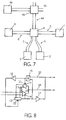
- FIG. 7 again shows the one known from FIG. 1 Topology of the network with nodes 1 to 4, line pairs 5 to 8 and the active star node 9.
- the active star node 9 is connected via a line pair 44 coupled to another active star node 45, to which in turn further network nodes can be connected.
- a network node 46 is shown here as an example.
- FIG. 8 shows a star interface suitable for the wired-OR connection.
- This star interface according to FIG. 8 is identical to the star interface of FIG. 2 except for the circuit-like connection of the output of the amplifier 17.
- the output of the amplifier 17 is thus connected to the inverting input of the AND gate 15.
- the amplifier 17 is shown in FIG Push-Pull "amplifier and in Fig. 8 as Open Collector "- or Open-drain "amplifier realized.
- the OR gate 23 is omitted in the active star node 9 and the result is a simple one Expandability of the network with further network nodes by eliminating the otherwise OR gate to be kept in different variants.
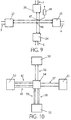
- the star interfaces 24 to 27 are connected to their respective lines 19 and 20 in this case, so that thereby forming two circuit nodes 47 and 48, as shown in FIG. 9.
- the resistor 49 the one with the circuit node 47 and the other is coupled to a supply voltage. This resistance forms together with the amplifiers 17 of each star interface, the wired OR link.
- the network of Fig. 10 contains four nodes 50 to 53 and a star node 54.
- the nodes 50 and 51 are via a pair of lines 56 and 57 and the nodes 52 and 53 via two each Line pairs 58 to 61 coupled to the star node 54. That means the network node 52 via the line pair 58 and 59 and the network node 53 via the line pair 60 and 61 is connected to the star node 54.
- FIG. 11 shows how a pilot signal is generated in a network node 52 and 53 and is sent over one of the line pairs 64 or 65.
- To generate a pilot signal serve the pilot signal generators 66 and 67.
- the lines 68 or 69 of a control unit 82 determine which pilot signal generator (66 or 67) generates a pilot signal.
- the pilot signal generator 66 or 67 delivers such a pilot signal to an associated multiplexer 70 or 71.
- the multiplexer 70 or 71 still receives a message or data via a line 72 or 73.
- the output signal of the multiplexer 70 or 71 is switched via a switchable amplifier 74 or 75 supplied to the respective line pair 64 or 65.
- Data originating from the star node 54 are transmitted via the line pair 64 or 65 fed to an amplifier 76 or 77.
- the amplifier 76 or 77 delivers the data a line 78 or 79 to further circuit components of the network node.
- a pilot signal detector 80 or 81 is connected to the output of each amplifier 76 or 77 connected.
- a control unit 82 state machine
- This control unit 82 controls the two switchable amplifiers 74 and 75.
- the control unit 82 controls the pilot signal generators 66 and 67 via lines 68 and 69.
- From the network node the start signal mentioned above is led on a line 83 to the control unit 82, which forms a control signal for the pilot signal generators 66 and 67.
- control unit 82 can report states to the network node, for example.
- circuit elements 66, 68, 70, 72, 74, 76, 78 and 80 form a first circuit component 85 and the circuit elements 67, 69, 71, 73, 75, 77, 79 and 81 a second Circuit component 86.
- Circuit components 85 and 86 are each identical built up.
- This control unit 82 manages the line pairs 64 and connected to the network node 65 so that the functionality of the line pairs 64 and 65 and the Circuit components 85 and 86 is checked.
- the control unit 82 checks whether the pilot signal actually arrives via both line pairs 64 and 65 - the arrival of one Pilot signal on one of the two redundant line pairs signals the start of one Receiving messages.
- the controller 82 checks during a particular one Time period whether after the arrival of the first pilot signal on one of the line pairs 64 or 65 the pilot signal has arrived on the other pair of lines. If not Case, it can be assumed that the other pair of lines is faulty.
- control unit 82 If there is no error and the control unit 82 has both line pairs 64 and 65 and has registered the two circuit components 85 and 86 as functional, for example, the circuit components 85 and 86 alternate with that send assigned star interface. In the event of an error, only the sends as error-free registered circuit component 85 or 86.
Landscapes
- Engineering & Computer Science (AREA)
- Computer Networks & Wireless Communication (AREA)
- Signal Processing (AREA)
- Small-Scale Networks (AREA)
Applications Claiming Priority (4)
| Application Number | Priority Date | Filing Date | Title |
|---|---|---|---|
| DE19944597 | 1999-09-16 | ||
| DE1999144596 DE19944596A1 (de) | 1999-09-16 | 1999-09-16 | Netzwerk mit mehreren Netzknoten und wenigstens einem Sternknoten |
| DE19944596 | 1999-09-16 | ||
| DE1999144597 DE19944597A1 (de) | 1999-09-16 | 1999-09-16 | Redundantes Netzwerk mit mehreren Netzknoten und wenigstens einem Sternknoten |
Publications (3)
| Publication Number | Publication Date |
|---|---|
| EP1085705A2 true EP1085705A2 (fr) | 2001-03-21 |
| EP1085705A3 EP1085705A3 (fr) | 2003-10-22 |
| EP1085705B1 EP1085705B1 (fr) | 2006-10-18 |
Family
ID=26054982
Family Applications (1)
| Application Number | Title | Priority Date | Filing Date |
|---|---|---|---|
| EP00203163A Expired - Lifetime EP1085705B1 (fr) | 1999-09-16 | 2000-09-12 | Réseau avec plusiers noeuds et au moins un noeud central |
Country Status (7)
| Country | Link |
|---|---|
| US (1) | US7099959B1 (fr) |
| EP (1) | EP1085705B1 (fr) |
| JP (1) | JP2001144792A (fr) |
| KR (1) | KR100686397B1 (fr) |
| CN (1) | CN1178433C (fr) |
| DE (1) | DE50013628D1 (fr) |
| ES (1) | ES2274763T3 (fr) |
Cited By (5)
| Publication number | Priority date | Publication date | Assignee | Title |
|---|---|---|---|---|
| EP1179921A3 (fr) * | 2000-08-10 | 2004-05-19 | Philips Intellectual Property & Standards GmbH | Détection d'activité dans un noeud central couplé à plusieurs noeuds |
| WO2004100449A1 (fr) * | 2003-05-08 | 2004-11-18 | Philips Intellectual Property & Standards Gmbh | Reseau de communication et procede de commande du reseau de communication |
| EP1213861A3 (fr) * | 2000-12-07 | 2005-10-05 | Siemens Aktiengesellschaft | Dispositif de noeud pour plusieurs dispositives étant réliés par un bus en série |
| WO2008107217A1 (fr) * | 2007-03-02 | 2008-09-12 | Robert Bosch Gmbh | Dispositif pour raccorder un appareil externe à un bus de données série flexray |
| EP1801967A3 (fr) * | 2005-12-22 | 2012-07-04 | Robert Bosch Gmbh | Point étoile actif pour installation dans un système de communication doté d'une topologie en étoile |
Families Citing this family (6)
| Publication number | Priority date | Publication date | Assignee | Title |
|---|---|---|---|---|
| EP1690377A2 (fr) * | 2003-11-19 | 2006-08-16 | Honeywell International Inc. | Arbitrage base sur la priorite pour mise en application d'un programme amrt dans un systeme multicanaux |
| US7366528B1 (en) * | 2004-01-13 | 2008-04-29 | At&T Mobility Ii Llc | Preventing wireless message delivery outside of specified times |
| WO2008029320A2 (fr) * | 2006-09-06 | 2008-03-13 | Nxp B.V. | Coupleur en étoile intelligent pour un protocole de communication déclenché temporellement et procédé de communication entre des nœuds dans un réseau utilisant un protocole déclenché temporellement |
| DE102008014254B4 (de) * | 2008-03-13 | 2014-11-27 | Audi Ag | Sternkoppler für ein Bussystem, Bussystem mit einem solchen Sternkoppler sowie Verfahren zum Austauschen von Signalen in einem Bussystem |
| KR101536921B1 (ko) * | 2009-01-07 | 2015-07-15 | 삼성전자주식회사 | 인지무선 시스템에서 전송휴지기간을 동기화하기 위한 방법 및 장치 |
| DE102009026430A1 (de) * | 2009-05-25 | 2010-12-09 | Robert Bosch Gmbh | Fahrzeugsensor, System mit einem Steuergerät zur Fahrzeugzustandsbestimmung und wenigstens zwei Fahrzeugsensoren und Verfahren zum Betreiben eines Systems mit einem Steuergerät zur Fahrzeugzustandsbestimmung und wenigstens zwei Fahrzeugsensoren |
Family Cites Families (21)
| Publication number | Priority date | Publication date | Assignee | Title |
|---|---|---|---|---|
| DE2917675A1 (de) * | 1979-04-27 | 1980-11-06 | Hertz Inst Heinrich | Digitales zeitmultiplex-nachrichtensystem |
| US4428046A (en) * | 1980-05-05 | 1984-01-24 | Ncr Corporation | Data processing system having a star coupler with contention circuitry |
| GB2155718B (en) * | 1984-03-08 | 1987-01-28 | Standard Telephones Cables Ltd | Local area network |
| JPS6167398A (ja) * | 1984-09-11 | 1986-04-07 | Kokusai Denshin Denwa Co Ltd <Kdd> | 光フアイバ信号分岐伝送方式 |
| US4630254A (en) * | 1984-10-26 | 1986-12-16 | Trw Inc. | Controlled star network |
| JPS61145995A (ja) * | 1984-12-20 | 1986-07-03 | Toshiba Corp | 集線分配装置 |
| US4781427A (en) * | 1985-09-19 | 1988-11-01 | The Mitre Corporation | Active star centered fiber optic local area network |
| US5189414A (en) * | 1986-09-30 | 1993-02-23 | Kabushiki Kaisha Toshiba | Network system for simultaneously coupling pairs of nodes |
| CA1322390C (fr) * | 1987-09-22 | 1993-09-21 | Nec Corporation | Reseau local en etoile |
| DE3919962C3 (de) * | 1989-06-19 | 1994-07-14 | Hirschmann Richard Gmbh Co | Verfahren und Anordnung zur Sicherung der Datenübertragung in einem linearen Rechnernetz |
| US5200949A (en) * | 1990-05-14 | 1993-04-06 | Fujitsu Limited | Link changeover control system for local area network of broadcasting arrangement |
| US5127067A (en) * | 1990-09-10 | 1992-06-30 | Westinghouse Electric Corp. | Local area network with star topology and ring protocol |
| DE4224339A1 (de) * | 1992-07-23 | 1994-01-27 | Sel Alcatel Ag | Bussystem für ein lokales Operationsnetzwerk |
| US5463488A (en) * | 1992-07-31 | 1995-10-31 | At&T Ipm Corp. | Distribution of clock signals by pump power modulation in an optically amplified network |
| DE19509558A1 (de) * | 1995-03-16 | 1996-09-19 | Abb Patent Gmbh | Verfahren zur fehlertoleranten Kommunikation unter hohen Echtzeitbedingungen |
| US6076117A (en) * | 1995-11-13 | 2000-06-13 | Billings; Roger E. | Packet merging hub system for sequentially merging received data in a network hub into data packets before broadcasting to a plurality of destination computers |
| US5764630A (en) * | 1996-03-25 | 1998-06-09 | Stanford Telecommunications, Inc. | Forward link carrier recovery in an OCDMA spread spectrum communication system without a pilot tone |
| US6493335B1 (en) * | 1996-09-24 | 2002-12-10 | At&T Corp. | Method and system for providing low-cost high-speed data services |
| JPH1117685A (ja) * | 1997-06-20 | 1999-01-22 | Oki Electric Ind Co Ltd | 帯域管理回路、伝送装置及び伝送システム |
| KR100309748B1 (ko) * | 1997-12-26 | 2001-12-17 | 윤종용 | 상향파일럿신호를이용한케이블에취에프씨망을위한양방향간선증폭기및에취에프씨망의케이블모뎀 |
| DE19950433A1 (de) * | 1999-10-19 | 2001-04-26 | Philips Corp Intellectual Pty | Netzwerk mit mehreren Netzknoten zur Medienzugangsprüfung |
-
2000
- 2000-09-12 ES ES00203163T patent/ES2274763T3/es not_active Expired - Lifetime
- 2000-09-12 DE DE50013628T patent/DE50013628D1/de not_active Expired - Lifetime
- 2000-09-12 CN CNB00130982XA patent/CN1178433C/zh not_active Expired - Fee Related
- 2000-09-12 EP EP00203163A patent/EP1085705B1/fr not_active Expired - Lifetime
- 2000-09-16 KR KR1020000054398A patent/KR100686397B1/ko not_active Expired - Fee Related
- 2000-09-18 JP JP2000281471A patent/JP2001144792A/ja not_active Withdrawn
- 2000-09-18 US US09/663,594 patent/US7099959B1/en not_active Expired - Lifetime
Cited By (6)
| Publication number | Priority date | Publication date | Assignee | Title |
|---|---|---|---|---|
| EP1179921A3 (fr) * | 2000-08-10 | 2004-05-19 | Philips Intellectual Property & Standards GmbH | Détection d'activité dans un noeud central couplé à plusieurs noeuds |
| KR100793451B1 (ko) * | 2000-08-10 | 2008-01-14 | 엔엑스피 비 브이 | 네트워크 및 스타 노드 |
| EP1213861A3 (fr) * | 2000-12-07 | 2005-10-05 | Siemens Aktiengesellschaft | Dispositif de noeud pour plusieurs dispositives étant réliés par un bus en série |
| WO2004100449A1 (fr) * | 2003-05-08 | 2004-11-18 | Philips Intellectual Property & Standards Gmbh | Reseau de communication et procede de commande du reseau de communication |
| EP1801967A3 (fr) * | 2005-12-22 | 2012-07-04 | Robert Bosch Gmbh | Point étoile actif pour installation dans un système de communication doté d'une topologie en étoile |
| WO2008107217A1 (fr) * | 2007-03-02 | 2008-09-12 | Robert Bosch Gmbh | Dispositif pour raccorder un appareil externe à un bus de données série flexray |
Also Published As
| Publication number | Publication date |
|---|---|
| ES2274763T3 (es) | 2007-06-01 |
| KR100686397B1 (ko) | 2007-02-23 |
| JP2001144792A (ja) | 2001-05-25 |
| DE50013628D1 (de) | 2006-11-30 |
| EP1085705B1 (fr) | 2006-10-18 |
| CN1292613A (zh) | 2001-04-25 |
| KR20010050487A (ko) | 2001-06-15 |
| CN1178433C (zh) | 2004-12-01 |
| US7099959B1 (en) | 2006-08-29 |
| EP1085705A3 (fr) | 2003-10-22 |
Similar Documents
| Publication | Publication Date | Title |
|---|---|---|
| DE10261174B3 (de) | Automatische Adressierung auf Bussystemen | |
| DE19950433A1 (de) | Netzwerk mit mehreren Netzknoten zur Medienzugangsprüfung | |
| DE10349600B4 (de) | Verfahren zur Überprüfung von Leitungsfehlern in einem Bussystem und Bussystem | |
| DE102012101957B3 (de) | Busteilnehmer-Einrichtung zum Anschluss an einen linienredundanten, seriellen Datenbus und Verfahren zur Steuerung der Kommunikation eines Busteilnehmers mit einem linienredundanten, seriellen Datenbus | |
| EP3977682B1 (fr) | Dispositif de test de détection d'erreur pour une station d'abonné d'un système de bus série et procédé de test de mécanismes de détection d'erreur lors d'une communication dans un système de bus série | |
| DE102008060007A1 (de) | Verfahren zum Übertragen von Daten in einem automatisierten Steuerungssystem | |
| WO2019030080A1 (fr) | Dispositif d'émission / réception pour un système de bus et procédé de réduction d'une disposition aux oscillations lors de la transition entre différents états binaires | |
| EP1085705A2 (fr) | Réseau avec plusiers noeuds et au moins un noeud central | |
| EP1687681A2 (fr) | Reseau, notamment reseau pa profibus, a proprietes de redondance, element de ramification pour appareil d'abonne dans un reseau de ce type, gestionnaire de redondance pour un reseau de ce type et procede pour faire fonctionner un reseau de ce type | |
| EP0214474A1 (fr) | Procédé et disposition pour transmettre des signaux de données entre les dispositifs de commande reliés entre eux par un système en anneau | |
| DE102009015944A1 (de) | Zeitteilermehrfahrzugriffs-Kommunikationsnetzwerksystem | |
| EP1179921B1 (fr) | Détection d'activité dans un noeud central couplé à plusieurs noeuds | |
| EP1227406A1 (fr) | Dispositif d'émission et de réception avec des moyens de gestion d'erreur | |
| EP1143668B1 (fr) | Solution des conflits d'acces aux supports dans des réseaux avec plusieurs noeuds et au moins un noed central | |
| DE102021127310B4 (de) | System und Verfahren zur Datenübertragung | |
| DE19944597A1 (de) | Redundantes Netzwerk mit mehreren Netzknoten und wenigstens einem Sternknoten | |
| EP4035314B1 (fr) | Dispositif esclave, système de bus et procédés | |
| DE102008049662B4 (de) | Verfahren und Vorrichtung zum Prüfen einer asynchronen Übertragung von Steuersignalen | |
| DE3327489C2 (fr) | ||
| EP3742680B1 (fr) | Dispositif distributeur et procédé correspondant | |
| DE19944596A1 (de) | Netzwerk mit mehreren Netzknoten und wenigstens einem Sternknoten | |
| DE19704021A1 (de) | Lichtwellenleiter-Bussystem mit in einer Ringstruktur angeordneten Teilnehmern | |
| DE102018221417B4 (de) | Fahrzeug mit einem Netzwerkverteiler zum Melden einer Störung in einem Kommunikationsnetzwerk | |
| EP3915227B1 (fr) | Dispositif d'émission/réception pour un poste d'abonné d'un système de bus série et procédé de communication dans un système de bus série | |
| WO2018162161A1 (fr) | Procédé et dispositif pour transmettre des informations sans rétroaction |
Legal Events
| Date | Code | Title | Description |
|---|---|---|---|
| PUAI | Public reference made under article 153(3) epc to a published international application that has entered the european phase |
Free format text: ORIGINAL CODE: 0009012 |
|
| AK | Designated contracting states |
Kind code of ref document: A2 Designated state(s): AT BE CH CY DE DK ES FI FR GB GR IE IT LI LU MC NL PT SE |
|
| AX | Request for extension of the european patent |
Free format text: AL;LT;LV;MK;RO;SI |
|
| RAP1 | Party data changed (applicant data changed or rights of an application transferred) |
Owner name: PHILIPS CORPORATE INTELLECTUAL PROPERTY GMBH Owner name: KONINKLIJKE PHILIPS ELECTRONICS N.V. |
|
| RAP1 | Party data changed (applicant data changed or rights of an application transferred) |
Owner name: KONINKLIJKE PHILIPS ELECTRONICS N.V. Owner name: PHILIPS INTELLECTUAL PROPERTY & STANDARDS GMBH |
|
| PUAL | Search report despatched |
Free format text: ORIGINAL CODE: 0009013 |
|
| AK | Designated contracting states |
Kind code of ref document: A3 Designated state(s): AT BE CH CY DE DK ES FI FR GB GR IE IT LI LU MC NL PT SE |
|
| AX | Request for extension of the european patent |
Extension state: AL LT LV MK RO SI |
|
| 17P | Request for examination filed |
Effective date: 20040422 |
|
| 17Q | First examination report despatched |
Effective date: 20040517 |
|
| AKX | Designation fees paid |
Designated state(s): DE ES FR GB IT |
|
| GRAP | Despatch of communication of intention to grant a patent |
Free format text: ORIGINAL CODE: EPIDOSNIGR1 |
|
| GRAS | Grant fee paid |
Free format text: ORIGINAL CODE: EPIDOSNIGR3 |
|
| GRAA | (expected) grant |
Free format text: ORIGINAL CODE: 0009210 |
|
| AK | Designated contracting states |
Kind code of ref document: B1 Designated state(s): DE ES FR GB IT |
|
| REG | Reference to a national code |
Ref country code: GB Ref legal event code: FG4D Free format text: NOT ENGLISH |
|
| REF | Corresponds to: |
Ref document number: 50013628 Country of ref document: DE Date of ref document: 20061130 Kind code of ref document: P |
|
| REG | Reference to a national code |
Ref country code: GB Ref legal event code: 732E |
|
| GBT | Gb: translation of ep patent filed (gb section 77(6)(a)/1977) |
Effective date: 20070116 |
|
| REG | Reference to a national code |
Ref country code: FR Ref legal event code: TP |
|
| ET | Fr: translation filed | ||
| REG | Reference to a national code |
Ref country code: ES Ref legal event code: FG2A Ref document number: 2274763 Country of ref document: ES Kind code of ref document: T3 |
|
| PLBE | No opposition filed within time limit |
Free format text: ORIGINAL CODE: 0009261 |
|
| STAA | Information on the status of an ep patent application or granted ep patent |
Free format text: STATUS: NO OPPOSITION FILED WITHIN TIME LIMIT |
|
| 26N | No opposition filed |
Effective date: 20070719 |
|
| REG | Reference to a national code |
Ref country code: ES Ref legal event code: PC2A |
|
| PGFP | Annual fee paid to national office [announced via postgrant information from national office to epo] |
Ref country code: DE Payment date: 20090910 Year of fee payment: 10 |
|
| PGFP | Annual fee paid to national office [announced via postgrant information from national office to epo] |
Ref country code: IT Payment date: 20090915 Year of fee payment: 10 |
|
| PG25 | Lapsed in a contracting state [announced via postgrant information from national office to epo] |
Ref country code: IT Free format text: LAPSE BECAUSE OF NON-PAYMENT OF DUE FEES Effective date: 20100912 |
|
| REG | Reference to a national code |
Ref country code: DE Ref legal event code: R119 Ref document number: 50013628 Country of ref document: DE Effective date: 20110401 |
|
| PG25 | Lapsed in a contracting state [announced via postgrant information from national office to epo] |
Ref country code: DE Free format text: LAPSE BECAUSE OF NON-PAYMENT OF DUE FEES Effective date: 20110401 |
|
| PGFP | Annual fee paid to national office [announced via postgrant information from national office to epo] |
Ref country code: ES Payment date: 20120910 Year of fee payment: 13 |
|
| REG | Reference to a national code |
Ref country code: ES Ref legal event code: FD2A Effective date: 20141010 |
|
| PGFP | Annual fee paid to national office [announced via postgrant information from national office to epo] |
Ref country code: GB Payment date: 20140910 Year of fee payment: 15 |
|
| PG25 | Lapsed in a contracting state [announced via postgrant information from national office to epo] |
Ref country code: ES Free format text: LAPSE BECAUSE OF NON-PAYMENT OF DUE FEES Effective date: 20130913 |
|
| PGFP | Annual fee paid to national office [announced via postgrant information from national office to epo] |
Ref country code: FR Payment date: 20140906 Year of fee payment: 15 |
|
| GBPC | Gb: european patent ceased through non-payment of renewal fee |
Effective date: 20150912 |
|
| REG | Reference to a national code |
Ref country code: FR Ref legal event code: ST Effective date: 20160531 |
|
| PG25 | Lapsed in a contracting state [announced via postgrant information from national office to epo] |
Ref country code: GB Free format text: LAPSE BECAUSE OF NON-PAYMENT OF DUE FEES Effective date: 20150912 |
|
| PG25 | Lapsed in a contracting state [announced via postgrant information from national office to epo] |
Ref country code: FR Free format text: LAPSE BECAUSE OF NON-PAYMENT OF DUE FEES Effective date: 20150930 |