EP1086363B1 - Automatische analysevorrichtung, zur feststellung der blutkoagulationszeit anwendbar - Google Patents
Automatische analysevorrichtung, zur feststellung der blutkoagulationszeit anwendbar Download PDFInfo
- Publication number
- EP1086363B1 EP1086363B1 EP99917005A EP99917005A EP1086363B1 EP 1086363 B1 EP1086363 B1 EP 1086363B1 EP 99917005 A EP99917005 A EP 99917005A EP 99917005 A EP99917005 A EP 99917005A EP 1086363 B1 EP1086363 B1 EP 1086363B1
- Authority
- EP
- European Patent Office
- Prior art keywords
- station
- receptacles
- pipette
- cup
- strip
- Prior art date
- Legal status (The legal status is an assumption and is not a legal conclusion. Google has not performed a legal analysis and makes no representation as to the accuracy of the status listed.)
- Expired - Lifetime
Links
- 238000004458 analytical method Methods 0.000 title claims abstract description 11
- 230000023555 blood coagulation Effects 0.000 title description 4
- 230000005291 magnetic effect Effects 0.000 claims abstract description 10
- 230000000694 effects Effects 0.000 claims abstract description 5
- 230000005294 ferromagnetic effect Effects 0.000 claims abstract description 5
- 230000000737 periodic effect Effects 0.000 claims abstract description 4
- 239000007788 liquid Substances 0.000 claims abstract description 3
- 238000012986 modification Methods 0.000 claims abstract description 3
- 230000004048 modification Effects 0.000 claims abstract description 3
- 238000001514 detection method Methods 0.000 claims description 12
- 238000002347 injection Methods 0.000 claims description 8
- 239000007924 injection Substances 0.000 claims description 8
- 239000008280 blood Substances 0.000 claims description 7
- 210000004369 blood Anatomy 0.000 claims description 7
- 238000005070 sampling Methods 0.000 claims description 7
- 238000011084 recovery Methods 0.000 claims description 2
- 239000003795 chemical substances by application Substances 0.000 claims 4
- 239000003153 chemical reaction reagent Substances 0.000 description 10
- 238000005259 measurement Methods 0.000 description 5
- 238000012360 testing method Methods 0.000 description 3
- 230000015271 coagulation Effects 0.000 description 2
- 238000005345 coagulation Methods 0.000 description 2
- 239000011324 bead Substances 0.000 description 1
- 238000013461 design Methods 0.000 description 1
- 238000009792 diffusion process Methods 0.000 description 1
- 238000006073 displacement reaction Methods 0.000 description 1
- 239000003302 ferromagnetic material Substances 0.000 description 1
- 239000012530 fluid Substances 0.000 description 1
- 230000001939 inductive effect Effects 0.000 description 1
- 239000000463 material Substances 0.000 description 1
- 238000000034 method Methods 0.000 description 1
- 238000000465 moulding Methods 0.000 description 1
- 230000005693 optoelectronics Effects 0.000 description 1
- 230000010355 oscillation Effects 0.000 description 1
- 230000002093 peripheral effect Effects 0.000 description 1
- 229920003023 plastic Polymers 0.000 description 1
- 239000000243 solution Substances 0.000 description 1
- 230000001360 synchronised effect Effects 0.000 description 1
- 238000012546 transfer Methods 0.000 description 1
Images
Classifications
-
- G—PHYSICS
- G01—MEASURING; TESTING
- G01N—INVESTIGATING OR ANALYSING MATERIALS BY DETERMINING THEIR CHEMICAL OR PHYSICAL PROPERTIES
- G01N35/00—Automatic analysis not limited to methods or materials provided for in any single one of groups G01N1/00 - G01N33/00; Handling materials therefor
- G01N35/02—Automatic analysis not limited to methods or materials provided for in any single one of groups G01N1/00 - G01N33/00; Handling materials therefor using a plurality of sample containers moved by a conveyor system past one or more treatment or analysis stations
- G01N35/021—Automatic analysis not limited to methods or materials provided for in any single one of groups G01N1/00 - G01N33/00; Handling materials therefor using a plurality of sample containers moved by a conveyor system past one or more treatment or analysis stations having a flexible chain, e.g. "cartridge belt", conveyor for reaction cells or cuvettes
-
- G—PHYSICS
- G01—MEASURING; TESTING
- G01N—INVESTIGATING OR ANALYSING MATERIALS BY DETERMINING THEIR CHEMICAL OR PHYSICAL PROPERTIES
- G01N11/00—Investigating flow properties of materials, e.g. viscosity, plasticity; Analysing materials by determining flow properties
- G01N11/10—Investigating flow properties of materials, e.g. viscosity, plasticity; Analysing materials by determining flow properties by moving a body within the material
- G01N11/16—Investigating flow properties of materials, e.g. viscosity, plasticity; Analysing materials by determining flow properties by moving a body within the material by measuring damping effect upon oscillatory body
-
- G—PHYSICS
- G01—MEASURING; TESTING
- G01N—INVESTIGATING OR ANALYSING MATERIALS BY DETERMINING THEIR CHEMICAL OR PHYSICAL PROPERTIES
- G01N33/00—Investigating or analysing materials by specific methods not covered by groups G01N1/00 - G01N31/00
- G01N33/48—Biological material, e.g. blood, urine; Haemocytometers
- G01N33/483—Physical analysis of biological material
- G01N33/487—Physical analysis of biological material of liquid biological material
- G01N33/49—Blood
- G01N33/4905—Determining clotting time of blood
-
- Y—GENERAL TAGGING OF NEW TECHNOLOGICAL DEVELOPMENTS; GENERAL TAGGING OF CROSS-SECTIONAL TECHNOLOGIES SPANNING OVER SEVERAL SECTIONS OF THE IPC; TECHNICAL SUBJECTS COVERED BY FORMER USPC CROSS-REFERENCE ART COLLECTIONS [XRACs] AND DIGESTS
- Y10—TECHNICAL SUBJECTS COVERED BY FORMER USPC
- Y10T—TECHNICAL SUBJECTS COVERED BY FORMER US CLASSIFICATION
- Y10T436/00—Chemistry: analytical and immunological testing
- Y10T436/11—Automated chemical analysis
Definitions
- the present invention relates to an automatic analysis apparatus which can be used in particular to the determination of the times of modification of the physical state of a fluid medium.
- each single-use cuvette has a shape small parallelepiped, the curved bottom of which forms the ball raceway, while the face opposite the bottom has an opening.
- These buckets are arranged side by side and fixed so detachable on a flexible support strip which temporarily seals their openings.
- the belt fitted with buckets can be wound on a reel can engage on a hub provided in a storage compartment and distribution system.
- an electronic camera takes an image of the plate with all its cavities in order to detect variations in the movement of ball
- the object of the invention is therefore more particularly to produce an apparatus simpler and less expensive in design but which nevertheless allows sufficient rates so as to be able to occupy the field of small and medium sizes.
- an analysis device automatic of the type in which a liquid sample to be analyzed is placed in a bowl containing a ferromagnetic ball entrained in a periodic movement under the effect of a magnetic field, this device including an electronic camera oriented towards the bowl and a processor able to detect from the image of the bowl changes in ball movements.
- this device is characterized in that it uses a plurality of cuvettes fixed on a support strip scrolling one by one in a detection, and in that the detection station comprises at least one camera electronics located below the bowls and electromagnetic means placed laterally with respect to the strip in line with the lateral faces of the cuvettes, so as to generate a magnetic field in the axis of displacement of the ball contained in the bowl located in the detection, the movement of movement of the strip may be of the step-by-step type not or even continuous.
- the electronic camera will be placed below the bowl, the electromagnetic means intended to generate the field magnetic outer being then arranged laterally, in the axis of moving the ball.
- the pipetting station may advantageously include a mobile pipette with both vertically and along a horizontal circular path so that ability to occupy an injection position located to the right of the bowl path in order to allow the injection of reagents inside them, a position of rinse located to the right of a rinse tank and at least one position reagent sampling located at the right of a sampling area of a reagent dispenser.
- This reagent dispenser may consist of a carousel comprising a plurality of movable reagent tanks in a circular path so as to be able to be brought successively into the sampling area.
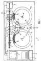
- the automatic analysis apparatus 1 involves a feeding in cuvettes comprising a coil 2 on which is wound a band B carrying a plurality of cuvettes C.
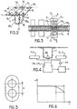
- the cups C produced by molding a transparent plastic material each have a body of flat parallelepiped shape, the curved bottom FI of which constitutes a raceway for a ball BE made of ferromagnetic material.
- the bowl C has an opening at the level of which its two opposite edges BO 1 , BO 2 are extended at right angles by two respective flanges R 1 , R 2 each provided with a cylindrical protuberance PC extending on the side opposite the body. These two protrusions are intended to force-engage in two respective holes TR respectively provided on the two lateral edges of the strip B.
- a P processor comprising a central unit as well as peripherals such as, for example example, a screen 8 / keyboard 9 assembly.
- the drive of the band B along its path is ensured by means of a step-by-step drive mechanism involving two endless bands B 1 , B 2 guided by rollers and bearing on the lateral faces of the bowls C carried by band B.
- the pipetting station 4 is served by an automated vertical pipette 10, movable in height, so that it can take a low position pipetting or rinsing and a high position allowing its movements in a horizontal plane.
- the pipette 10 can be brought successively at the pipetting area of the pipetting station 4, at an area of flush 13 diametrically opposite, equipped with one or more tanks rinsing and two sampling areas 14, 15 arranged symmetrically by relative to the axis passing through the pipetting area 4 and the rinsing area 13.
- the sampling areas 14, 15 are located in the path of containers R 1 , R 2 carried by two respective carousels CR 1 , CR 2 movable in rotation around two vertical axes 17, 18 and controlled by two servomotors controlled by the processor P .
- One of these CR 1 carousels is intended to contain the containers R 1 of blood samples to be analyzed while the other CR 2 contains containers R 2 assigned to the various reagents usable within the framework of the analyzes which it is wished to carry out. .
- the electromagnets E 1 , E ' 1 - E 2 , E' 2 - E 3 , E ' 3 are excited by a power circuit PR controlled by the processor P so as to generate a pulsed magnetic field capable of causing the ball BE according to an alternative movement at the bottom of the bowl C.
- the camera CM 1 - CM 3 is coupled to the processor P which analyzes, in real time, the image using appropriate software, so as to measure the amplitude of the BE ball oscillations and determine the critical instant when this amplitude drops below a determined threshold (for example 50% of the initial amplitude) ( Figures 5 and 6).
- a determined threshold for example 50% of the initial amplitude
- the processor P counts the time between the moment where the reagent was injected into cuvette C and this critical moment, so that deduce a coagulation time.
- stepwise movements of the strip are synchronized with the operating times of each of the machine's stations, and in particular with the magnetic field pulses generated by the coils.
- the pipetting station can be located in one location as the measuring station.
- each camera could present a field including several cuvettes each excited by a couple of separate electromagnets, way to follow the bowl on a multi-step advance with a processor P programmed to simultaneously detect the movements of the balls of different bowls.
Landscapes
- Health & Medical Sciences (AREA)
- Life Sciences & Earth Sciences (AREA)
- Chemical & Material Sciences (AREA)
- Engineering & Computer Science (AREA)
- Physics & Mathematics (AREA)
- Pathology (AREA)
- Biomedical Technology (AREA)
- General Health & Medical Sciences (AREA)
- General Physics & Mathematics (AREA)
- Immunology (AREA)
- Analytical Chemistry (AREA)
- Biochemistry (AREA)
- Hematology (AREA)
- Chemical Kinetics & Catalysis (AREA)
- Ecology (AREA)
- Biophysics (AREA)
- Molecular Biology (AREA)
- Urology & Nephrology (AREA)
- Food Science & Technology (AREA)
- Medicinal Chemistry (AREA)
- Investigating Or Analysing Biological Materials (AREA)
- Automatic Analysis And Handling Materials Therefor (AREA)
- Investigating Or Analyzing Materials By The Use Of Magnetic Means (AREA)
Claims (9)
- Gerät für die automatische Analyse, von dem Typ, bei dem eine zu analysierende flüssige Probe in einen Behälter (C) gebracht wird, der eine ferromagnetische Kugel (BE) enthält, die unter Einwirkung eines Magnetfeldes in eine regelmäßige Bewegung versetzt wird, wobei das Gerät eine elektronische Kamera (CM1, CM3) beinhaltet, die auf den Behälter (C) gerichtet ist, und einen Prozessor (P), der in der Lage ist, anhand des Bildes des Behälters (C) Veränderungen der Bewegungen der Kugel (BE) festzustellen, dadurch gekennzeichnet, dass das Gerät eine Vielzahl von Behältern verwendet, die an einem Transportband (B) befestigt sind und nacheinander an einer Sensorstation (5) vorbeilaufen, und dadurch, dass die Sensorstation mindestens eine elektronische Kamera (CM1, CM3) beinhaltet, die unter den Behältern angeordnet ist, und elektromagnetische Vorrichtungen, die im Verhältnis zum Band (B) seitlich und gegenüber den Seitenflächen der Behälter angeordnet sind, so dass in der Bewegungsachse der Kugel, die sich in dem Behälter befindet, der sich gerade in der Sensorstation befindet, ein Magnetfeld erzeugt wird, wobei die Bewegungsart des Bandes (B) eine schrittweise oder auch eine gleichmäßige Bewegung sein kann.
- Gerät gemäß Patentanspruch 1,
dadurch gekennzeichnet, dass das Band (B) einem geradlinigen Weg folgt, der nacheinander an einer eventuellen Station für das Einschneiden des Bandes (B), einer Pipettenstation (4), einer Sensorstation (5) und einer Auffangstation (6) für das Band mit den gebrauchten Behältern vorbeiführt. - Gerät gemäß einem der voranstehenden Patentansprüche,
dadurch gekennzeichnet, dass die Pipettenstation (4) von einer senkrecht angeordneten Pipette (10) bedient wird, deren Höhe verstellbar ist und die an einem Ende eines Amis (11) befestigt ist, der um eine senkrechte Achse drehbar montiert ist, so dass er durch Rotation nacheinander in den Pipettierbereich, in einen Spülbereich und in zwei Entnahmebereiche (14, 15) geführt werden kann. - Gerät gemäß Patentanspruch 3,
dadurch gekennzeichnet, dass die Entnahmebereiche (14, 15) auf dem Arbeitsweg der Behälter ( R1, R2) angeordnet sind, die von zwei Karussells (CR1, CR2) getragen werden, die sich um zwei senkrechte Achsen (17, 18) drehen, die von zwei Servomotoren betätigt werden, wobei eines der Karussells (CR1) für die Aufnahme der Behälter (R1) mit den Blutproben bestimmt ist, während das andere (CR2) Behälter (R2) für die Reaktionsmittel enthält, die im Rahmen der durchzuführenden Analysen verwendet werden können. - Gerät gemäß Patentanspruch 4,
dadurch gekennzeichnet, dass es einen Prozessor (P) beinhaltet, der so programmiert ist, dass er Pipettiersequenzen steuert, die nacheinander folgende Schritte beinhalten:einen vorausgehenden Spülvorgang der Pipette (10),die Entnahme einer Probendosis, die in einem der Behälter (R1) von Karussell (CR1) enthalten sind,die Injektion dieser Dosis in einen Behälter (C), der sich in der Pipettenstation (4) befindet,das Spülen der Pipette (10),die Entnahme einer Dosis eines Reaktionsmittels, das in einem der Behälter (R2) von Karussell (CR2) enthalten ist,Injektion dieser Dosis eines Reaktionsmittels in den Behälter (C). - Gerät gemäß Patentanspruch 5,
dadurch gekennzeichnet, dass die Identifizierung der zu analysierenden Blutproben sowie der Reaktionsmittel automatisch mithilfe eines Strichcodelesers (19) erfolgt, der in der Lage ist, die Strichcodes zu lesen, die auf den Behältern ( R1, R2) angebracht sind sind, die in den Karussells (CR1, CR2) stehen. - Gerät gemäß Patentanspruch 6,
dadurch gekennzeichnet, dass es einen einzigen Strichcodeleser (19) beinhaltet, der am Ende eines Arms (20) montiert ist, der sich so um eine senkrechte Achse (21) dreht, dass er drei Positionen einnehmen kann, nämlicheine Position (P1) für das Lesen der Strichcodes auf den Behältern (R1) von Karussell (CR1),eine Position (P2) für das Lesen der Strichcodes auf den Behältern (R2) von Karussell (CR2),eine Position (P3) für das Lesen der Behälter, die vom Bediener in eine Lesestation gestellt werden, z.B. um Informationen zu erfassen, die vom Prozessor im Rahmen des Gerätebetriebs verwendet werden. - Gerät gemäß irgendeinem der voranstehenden Patentansprüche,
dadurch gekennzeichnet, dass das Blickfeld der Kamera (CM1 - CM3) mehrere Behälter C) einschließt, die jeweils von verschiedenen elektromagnetischen Vorrichtungen erregt werden, - Gerät gemäß Patentanspruch 8,
dadurch gekennzeichnet, dass der Prozessor (P) so programmiert ist, dass er simultan die Bewegungen der Kugeln (BE) in den genannten Behältern (C) feststellt.
Applications Claiming Priority (3)
| Application Number | Priority Date | Filing Date | Title |
|---|---|---|---|
| FR9807484A FR2779827B1 (fr) | 1998-06-10 | 1998-06-10 | Appareil d'analyse automatique utilisable pour la determination du temps de coagulation du sang |
| FR9807484 | 1998-06-10 | ||
| PCT/FR1999/001082 WO1999064839A1 (fr) | 1998-06-10 | 1999-05-06 | Appareil d'analyse automatique utilisable pour la determination du temps de coagulation du sang |
Publications (2)
| Publication Number | Publication Date |
|---|---|
| EP1086363A1 EP1086363A1 (de) | 2001-03-28 |
| EP1086363B1 true EP1086363B1 (de) | 2002-01-09 |
Family
ID=9527367
Family Applications (1)
| Application Number | Title | Priority Date | Filing Date |
|---|---|---|---|
| EP99917005A Expired - Lifetime EP1086363B1 (de) | 1998-06-10 | 1999-05-06 | Automatische analysevorrichtung, zur feststellung der blutkoagulationszeit anwendbar |
Country Status (13)
| Country | Link |
|---|---|
| US (1) | US6767511B1 (de) |
| EP (1) | EP1086363B1 (de) |
| JP (1) | JP4266517B2 (de) |
| CN (1) | CN1145024C (de) |
| AT (1) | ATE211819T1 (de) |
| AU (1) | AU760171B2 (de) |
| CA (1) | CA2334759A1 (de) |
| DE (1) | DE69900793T2 (de) |
| DK (1) | DK1086363T3 (de) |
| ES (1) | ES2170578T3 (de) |
| FR (1) | FR2779827B1 (de) |
| PT (1) | PT1086363E (de) |
| WO (1) | WO1999064839A1 (de) |
Families Citing this family (33)
| Publication number | Priority date | Publication date | Assignee | Title |
|---|---|---|---|---|
| KR100916000B1 (ko) | 2002-02-01 | 2009-09-10 | 디아그노스티카 스타고 | 분석장치의 보울 구동장치 |
| FR2835617B1 (fr) * | 2002-02-01 | 2004-04-30 | Junior Instruments | Dispositif d'entrainement d'une bande de cuvettes dans un appareil d'analyse |
| FR2835616B1 (fr) | 2002-02-01 | 2005-02-11 | Junior Instruments | Dispositif pour l'analyse automatisee d'un echantillon liquide |
| GB0324641D0 (en) * | 2003-10-22 | 2003-11-26 | Unipath Ltd | Coagulation detection method |
| EP1544596B1 (de) * | 2003-12-17 | 2016-11-23 | Boehringer Ingelheim microParts GmbH | Verfahren und Vorrichtung zur Bestimmung der Viskosität |
| FR2873447B1 (fr) | 2004-07-23 | 2007-09-28 | Alain Michel Rousseau | Analyseur automatique pluridisciplinaire pour le diagnostic in vitro |
| FR2896589B1 (fr) * | 2006-01-25 | 2008-04-25 | Biocode Hycel France Sa Sa | Cuvette d'analyse polyvalente |
| CN101000352B (zh) * | 2007-01-17 | 2012-03-07 | 李钢 | 一种液体凝固时间的测量装置 |
| FR2911688B1 (fr) * | 2007-01-23 | 2009-04-17 | Stago Diagnostica | Cuvette de reaction pour appareil d'analyse automatique. |
| CN101315388B (zh) * | 2007-06-01 | 2012-07-04 | 北京普利生仪器有限公司 | 测试杯耗材控制系统及控制方法 |
| EP2040073A1 (de) * | 2007-09-20 | 2009-03-25 | Iline Microsystems, S.L. | Mikrofluidische Vorrichtung und Verfahren zur Flüssigkeitsgerinnungs-Zeitbestimmung |
| CN104777291B (zh) * | 2007-10-10 | 2017-09-12 | 普凯尔德诊断技术有限公司 | 用于鉴定尿中细菌的系统 |
| US9670551B2 (en) | 2007-11-30 | 2017-06-06 | Genomictree, Inc. | Diagnosis kit and chip for bladder cancer using bladder cancer specific methylation marker gene |
| EP2245467B1 (de) | 2008-02-05 | 2022-04-06 | Pocared Diagnostics Ltd. | System zur durchführung der identifizierung von bakterien in biologischen proben |
| US10288632B2 (en) * | 2009-09-21 | 2019-05-14 | Pocared Diagnostics Ltd. | System for conducting the identification of bacteria in biological samples |
| EP2508891B1 (de) * | 2009-12-04 | 2019-08-07 | Hitachi High-Technologies Corporation | Blutgerinnungsanalysegerät |
| FR2965622A1 (fr) * | 2010-10-05 | 2012-04-06 | Stago Diagnostica | Cuvette de reaction pour appareil automatique d'analyse chimique ou biologique |
| JP6279609B2 (ja) | 2012-12-11 | 2018-02-14 | ポカード・ディアグノスティクス・リミテッドPocared Diagnostics, Ltd. | 湾曲底部を備える光学カップ |
| US10823743B1 (en) | 2013-10-28 | 2020-11-03 | Ifirst Medical Technologies, Inc. | Methods of measuring coagulation of a biological sample |
| JP6320535B2 (ja) * | 2014-07-29 | 2018-05-09 | 株式会社日立ハイテクノロジーズ | 自動分析装置 |
| US9562840B2 (en) | 2014-12-03 | 2017-02-07 | Cambridge Viscosity, Inc. | High precision reciprocating bob viscometer |
| CN104568665B (zh) * | 2014-12-06 | 2017-07-07 | 深圳市前海安测信息技术有限公司 | 测量液体凝滞时间的方法 |
| FR3030048B1 (fr) * | 2014-12-15 | 2016-12-23 | Immunodiagnostic Systems France | Procede et dispositif de determination du temps de coagulation d’un echantillon sanguin, et cuvette de reaction |
| ES3038129T3 (en) | 2015-06-26 | 2025-10-09 | Abbott Lab | Rotating device in a diagnostic analyzer |
| EP3178556A1 (de) * | 2015-12-10 | 2017-06-14 | Holger Behnk | Küvette und messverfahren |
| TWI766942B (zh) | 2017-02-13 | 2022-06-11 | 美商海科生醫有限責任公司 | 透過利用瞬態和穩態間隔振動移液管來混合流體或介質的設備和方法 |
| CN107765021B (zh) * | 2017-11-24 | 2024-07-12 | 北京众驰伟业科技发展有限公司 | 一种测试杯集成式测试位 |
| US20210302412A1 (en) * | 2018-07-25 | 2021-09-30 | Ifirst Medical Technologies, Inc. | Medical analyzer and diagnostic sample profiler |
| CN112881234A (zh) * | 2019-11-29 | 2021-06-01 | 深圳市帝迈生物技术有限公司 | 容纳结构、液体状态检测装置及其方法、样本分析仪 |
| CN112881235B (zh) * | 2019-11-29 | 2021-11-16 | 深圳市帝迈生物技术有限公司 | 一种样本分析装置和计算凝固时长的方法 |
| US12277814B2 (en) | 2020-01-29 | 2025-04-15 | Ifirst Medical Technologies, Inc. | Medical analyzer and diagnostic sample profiler |
| CN111735970B (zh) * | 2020-07-23 | 2020-12-01 | 南京岚煜生物科技有限公司 | 一种凝血分析系统进行凝血分析的方法 |
| CN115078702B (zh) * | 2021-03-12 | 2025-01-14 | 重庆南方数控设备股份有限公司 | 一种基于磁珠的血栓弹力图检测装置及方法 |
Family Cites Families (8)
| Publication number | Priority date | Publication date | Assignee | Title |
|---|---|---|---|---|
| FR2566908B1 (fr) * | 1984-06-27 | 1986-07-18 | Girolami Antoine | Coagulometre et procede de mesure du temps de coagulation d'echantillons de produits fluides |
| DE3540661A1 (de) * | 1985-11-16 | 1987-05-21 | Amelung Gmbh Heinrich | Anlage zur messung der blutgerinnungszeit |
| DE3738375A1 (de) * | 1987-11-12 | 1989-05-24 | Amelung Gmbh Heinrich | Vorrichtung zum einsetzen von mit stahlkugeln bestueckten testkuevetten in eine messvorrichtung eines analysegeraetes |
| FR2634020B2 (fr) * | 1987-12-30 | 1991-02-22 | Serbio | Cuvette pour analyseur biologique |
| EP0596883A4 (de) * | 1991-07-26 | 1994-12-07 | Cirrus Diagnostics Inc | Automatisches analysiergerät für immunoassays. |
| EP0525273B1 (de) * | 1991-08-02 | 1996-10-16 | Grupo Grifols, S.A. | Verfahren und Vorrichtung zur Bestimmung der Gerinnungszeit von Blut und Plasma |
| US5394739A (en) * | 1994-06-06 | 1995-03-07 | Computational Systems, Inc. | Viscosity tester and method with orbiting object |
| US5885529A (en) * | 1996-06-28 | 1999-03-23 | Dpc Cirrus, Inc. | Automated immunoassay analyzer |
-
1998
- 1998-06-10 FR FR9807484A patent/FR2779827B1/fr not_active Expired - Lifetime
-
1999
- 1999-05-06 PT PT99917005T patent/PT1086363E/pt unknown
- 1999-05-06 AT AT99917005T patent/ATE211819T1/de not_active IP Right Cessation
- 1999-05-06 DE DE69900793T patent/DE69900793T2/de not_active Expired - Lifetime
- 1999-05-06 CA CA002334759A patent/CA2334759A1/en not_active Abandoned
- 1999-05-06 ES ES99917005T patent/ES2170578T3/es not_active Expired - Lifetime
- 1999-05-06 EP EP99917005A patent/EP1086363B1/de not_active Expired - Lifetime
- 1999-05-06 DK DK99917005T patent/DK1086363T3/da active
- 1999-05-06 JP JP2000553784A patent/JP4266517B2/ja not_active Expired - Lifetime
- 1999-05-06 US US09/719,091 patent/US6767511B1/en not_active Expired - Lifetime
- 1999-05-06 CN CNB998071781A patent/CN1145024C/zh not_active Expired - Lifetime
- 1999-05-06 AU AU35290/99A patent/AU760171B2/en not_active Ceased
- 1999-05-06 WO PCT/FR1999/001082 patent/WO1999064839A1/fr not_active Ceased
Also Published As
| Publication number | Publication date |
|---|---|
| AU760171B2 (en) | 2003-05-08 |
| HK1032264A1 (en) | 2001-07-13 |
| JP2002517749A (ja) | 2002-06-18 |
| PT1086363E (pt) | 2002-05-31 |
| DE69900793T2 (de) | 2005-07-07 |
| DK1086363T3 (da) | 2002-04-29 |
| AU3529099A (en) | 1999-12-30 |
| ES2170578T3 (es) | 2002-08-01 |
| DE69900793D1 (de) | 2002-02-28 |
| FR2779827B1 (fr) | 2000-08-11 |
| CA2334759A1 (en) | 1999-12-16 |
| US6767511B1 (en) | 2004-07-27 |
| JP4266517B2 (ja) | 2009-05-20 |
| CN1305585A (zh) | 2001-07-25 |
| EP1086363A1 (de) | 2001-03-28 |
| FR2779827A1 (fr) | 1999-12-17 |
| WO1999064839A1 (fr) | 1999-12-16 |
| CN1145024C (zh) | 2004-04-07 |
| ATE211819T1 (de) | 2002-01-15 |
Similar Documents
| Publication | Publication Date | Title |
|---|---|---|
| EP1086363B1 (de) | Automatische analysevorrichtung, zur feststellung der blutkoagulationszeit anwendbar | |
| EP1470425B1 (de) | Vorrichtung zur automatisierten analyse flüssiger proben | |
| JP3045336B2 (ja) | 吸引プローブのセンターリング装置及びセンターリング方法 | |
| BE1001048A5 (fr) | Instrument automatise pour analyse d'echantillon de patient. | |
| EP1976636B1 (de) | Einheitenküvette zur analyse eines biologischen fluids und automatische vorrichtung zur in-vitro-analyse | |
| JPH0736284Y2 (ja) | 検体容器の検体識別コード読取装置 | |
| JPH0321870B2 (de) | ||
| US5411065A (en) | Liquid specimen transfer apparatus and method | |
| CA2180364A1 (fr) | Appareil automatique de dosage immunologique | |
| EP2917741A1 (de) | Analysevorrichtung für in-vitro-diagnostik | |
| CA1313487C (en) | Analyzer with wash station separate from incubator | |
| JPH0251153B2 (de) | ||
| JPH04235352A (ja) | 液体充填容器の搬送装置 | |
| EP1470426B1 (de) | Antriebsvorrichtung einer küvettenkette in einer analysevorrichtung | |
| FR2474697A1 (fr) | Mecanisme de transfert de fluide a plusieurs positions | |
| FR2726653A1 (fr) | Dispositif pour la collecte ou la distribution d'echatillons liquides | |
| JP7467306B2 (ja) | 試薬容器、試薬提供装置及び自動分析装置 | |
| JPS61258170A (ja) | 免疫学的分析に用いられる担体収納容器 | |
| HK1032264B (en) | Automatic analysis apparatus used for timing blood coagulation | |
| HK1069436B (en) | Device for automatic analysis of a liquid sample |
Legal Events
| Date | Code | Title | Description |
|---|---|---|---|
| PUAI | Public reference made under article 153(3) epc to a published international application that has entered the european phase |
Free format text: ORIGINAL CODE: 0009012 |
|
| 17P | Request for examination filed |
Effective date: 20001207 |
|
| AK | Designated contracting states |
Kind code of ref document: A1 Designated state(s): AT BE CH CY DE DK ES FI FR GB GR IE IT LI LU MC NL PT SE |
|
| GRAG | Despatch of communication of intention to grant |
Free format text: ORIGINAL CODE: EPIDOS AGRA |
|
| 17Q | First examination report despatched |
Effective date: 20010510 |
|
| GRAG | Despatch of communication of intention to grant |
Free format text: ORIGINAL CODE: EPIDOS AGRA |
|
| GRAH | Despatch of communication of intention to grant a patent |
Free format text: ORIGINAL CODE: EPIDOS IGRA |
|
| GRAH | Despatch of communication of intention to grant a patent |
Free format text: ORIGINAL CODE: EPIDOS IGRA |
|
| GRAA | (expected) grant |
Free format text: ORIGINAL CODE: 0009210 |
|
| REG | Reference to a national code |
Ref country code: GB Ref legal event code: IF02 |
|
| AK | Designated contracting states |
Kind code of ref document: B1 Designated state(s): AT BE CH CY DE DK ES FI FR GB GR IE IT LI LU MC NL PT SE |
|
| REF | Corresponds to: |
Ref document number: 211819 Country of ref document: AT Date of ref document: 20020115 Kind code of ref document: T |
|
| REG | Reference to a national code |
Ref country code: CH Ref legal event code: EP |
|
| REG | Reference to a national code |
Ref country code: IE Ref legal event code: FG4D Free format text: FRENCH |
|
| REG | Reference to a national code |
Ref country code: CH Ref legal event code: NV Representative=s name: BUGNION S.A. |
|
| REF | Corresponds to: |
Ref document number: 69900793 Country of ref document: DE Date of ref document: 20020228 |
|
| REG | Reference to a national code |
Ref country code: DK Ref legal event code: T3 |
|
| REG | Reference to a national code |
Ref country code: PT Ref legal event code: SC4A Free format text: AVAILABILITY OF NATIONAL TRANSLATION Effective date: 20020220 |
|
| GBT | Gb: translation of ep patent filed (gb section 77(6)(a)/1977) |
Effective date: 20020530 |
|
| REG | Reference to a national code |
Ref country code: GR Ref legal event code: EP Ref document number: 20020401110 Country of ref document: GR |
|
| REG | Reference to a national code |
Ref country code: ES Ref legal event code: FG2A Ref document number: 2170578 Country of ref document: ES Kind code of ref document: T3 |
|
| PLBE | No opposition filed within time limit |
Free format text: ORIGINAL CODE: 0009261 |
|
| STAA | Information on the status of an ep patent application or granted ep patent |
Free format text: STATUS: NO OPPOSITION FILED WITHIN TIME LIMIT |
|
| 26N | No opposition filed | ||
| PGFP | Annual fee paid to national office [announced via postgrant information from national office to epo] |
Ref country code: MC Payment date: 20030408 Year of fee payment: 5 |
|
| PGFP | Annual fee paid to national office [announced via postgrant information from national office to epo] |
Ref country code: CY Payment date: 20030418 Year of fee payment: 5 |
|
| PG25 | Lapsed in a contracting state [announced via postgrant information from national office to epo] |
Ref country code: MC Free format text: LAPSE BECAUSE OF NON-PAYMENT OF DUE FEES Effective date: 20040406 |
|
| PG25 | Lapsed in a contracting state [announced via postgrant information from national office to epo] |
Ref country code: CY Free format text: LAPSE BECAUSE OF NON-PAYMENT OF DUE FEES Effective date: 20040506 |
|
| PG25 | Lapsed in a contracting state [announced via postgrant information from national office to epo] |
Ref country code: IT Free format text: LAPSE BECAUSE OF NON-PAYMENT OF DUE FEES Effective date: 20050506 |
|
| REG | Reference to a national code |
Ref country code: CH Ref legal event code: PLI Owner name: DIAGNOSTICA STAGO Free format text: STAGO INSTRUMENTS#125, AVENUE LOUIS ROCHE#92230 GENNEVILLIERS (FR) -TRANSFER TO- DIAGNOSTICA STAGO#9, RUE DES FRERES CHAUSSON#92600 ASNIERES (FR) Ref country code: CH Ref legal event code: PFA Owner name: STAGO INSTRUMENTS Free format text: JUNIOR INSTRUMENTS#125, AVENUE LOUIS ROCHE#92230 GENNEVILLIERS (FR) -TRANSFER TO- STAGO INSTRUMENTS#125, AVENUE LOUIS ROCHE#92230 GENNEVILLIERS (FR) |
|
| REG | Reference to a national code |
Ref country code: PT Ref legal event code: QB4A Owner name: DIAGNOSTICA STAGO, FR Effective date: 20050817 Ref country code: PT Ref legal event code: PD4A Owner name: STAGO INSTRUMENTS, FR Effective date: 20050817 |
|
| REG | Reference to a national code |
Ref country code: GB Ref legal event code: 732E |
|
| REG | Reference to a national code |
Ref country code: FR Ref legal event code: CL Ref country code: FR Ref legal event code: CD |
|
| NLT1 | Nl: modifications of names registered in virtue of documents presented to the patent office pursuant to art. 16 a, paragraph 1 |
Owner name: STAGO INSTRUMENTS |
|
| NLUE | Nl: licence registered with regard to european patents |
Effective date: 20060421 |
|
| REG | Reference to a national code |
Ref country code: ES Ref legal event code: PC2A |
|
| REG | Reference to a national code |
Ref country code: ES Ref legal event code: GD2A Effective date: 20061005 |
|
| PGFP | Annual fee paid to national office [announced via postgrant information from national office to epo] |
Ref country code: PT Payment date: 20070411 Year of fee payment: 9 Ref country code: IE Payment date: 20070411 Year of fee payment: 9 |
|
| PGFP | Annual fee paid to national office [announced via postgrant information from national office to epo] |
Ref country code: AT Payment date: 20070420 Year of fee payment: 9 |
|
| PGFP | Annual fee paid to national office [announced via postgrant information from national office to epo] |
Ref country code: FI Payment date: 20070504 Year of fee payment: 9 |
|
| PGFP | Annual fee paid to national office [announced via postgrant information from national office to epo] |
Ref country code: LU Payment date: 20070511 Year of fee payment: 9 |
|
| PGFP | Annual fee paid to national office [announced via postgrant information from national office to epo] |
Ref country code: SE Payment date: 20070515 Year of fee payment: 9 Ref country code: DK Payment date: 20070515 Year of fee payment: 9 Ref country code: BE Payment date: 20070515 Year of fee payment: 9 |
|
| PGFP | Annual fee paid to national office [announced via postgrant information from national office to epo] |
Ref country code: NL Payment date: 20070530 Year of fee payment: 9 |
|
| PGFP | Annual fee paid to national office [announced via postgrant information from national office to epo] |
Ref country code: CH Payment date: 20070607 Year of fee payment: 9 |
|
| PGFP | Annual fee paid to national office [announced via postgrant information from national office to epo] |
Ref country code: GR Payment date: 20070413 Year of fee payment: 9 |
|
| REG | Reference to a national code |
Ref country code: PT Ref legal event code: MM4A Free format text: LAPSE DUE TO NON-PAYMENT OF FEES Effective date: 20081106 |
|
| BERE | Be: lapsed |
Owner name: *STAGO INSTRUMENTS Effective date: 20080531 |
|
| REG | Reference to a national code |
Ref country code: CH Ref legal event code: PL |
|
| REG | Reference to a national code |
Ref country code: DK Ref legal event code: EBP |
|
| PG25 | Lapsed in a contracting state [announced via postgrant information from national office to epo] |
Ref country code: PT Free format text: LAPSE BECAUSE OF NON-PAYMENT OF DUE FEES Effective date: 20081106 Ref country code: NL Free format text: LAPSE BECAUSE OF NON-PAYMENT OF DUE FEES Effective date: 20081201 Ref country code: LI Free format text: LAPSE BECAUSE OF NON-PAYMENT OF DUE FEES Effective date: 20080531 Ref country code: CH Free format text: LAPSE BECAUSE OF NON-PAYMENT OF DUE FEES Effective date: 20080531 |
|
| REG | Reference to a national code |
Ref country code: IE Ref legal event code: MM4A |
|
| PG25 | Lapsed in a contracting state [announced via postgrant information from national office to epo] |
Ref country code: FI Free format text: LAPSE BECAUSE OF NON-PAYMENT OF DUE FEES Effective date: 20080506 Ref country code: AT Free format text: LAPSE BECAUSE OF NON-PAYMENT OF DUE FEES Effective date: 20080506 |
|
| PG25 | Lapsed in a contracting state [announced via postgrant information from national office to epo] |
Ref country code: BE Free format text: LAPSE BECAUSE OF NON-PAYMENT OF DUE FEES Effective date: 20080531 |
|
| PG25 | Lapsed in a contracting state [announced via postgrant information from national office to epo] |
Ref country code: IE Free format text: LAPSE BECAUSE OF NON-PAYMENT OF DUE FEES Effective date: 20080506 Ref country code: DK Free format text: LAPSE BECAUSE OF NON-PAYMENT OF DUE FEES Effective date: 20080531 |
|
| PG25 | Lapsed in a contracting state [announced via postgrant information from national office to epo] |
Ref country code: GR Free format text: LAPSE BECAUSE OF NON-PAYMENT OF DUE FEES Effective date: 20081204 |
|
| PGRI | Patent reinstated in contracting state [announced from national office to epo] |
Ref country code: IT Effective date: 20090501 |
|
| PG25 | Lapsed in a contracting state [announced via postgrant information from national office to epo] |
Ref country code: LU Free format text: LAPSE BECAUSE OF NON-PAYMENT OF DUE FEES Effective date: 20080506 |
|
| PG25 | Lapsed in a contracting state [announced via postgrant information from national office to epo] |
Ref country code: SE Free format text: LAPSE BECAUSE OF NON-PAYMENT OF DUE FEES Effective date: 20080507 |
|
| PGFP | Annual fee paid to national office [announced via postgrant information from national office to epo] |
Ref country code: ES Payment date: 20120524 Year of fee payment: 14 |
|
| PGFP | Annual fee paid to national office [announced via postgrant information from national office to epo] |
Ref country code: GB Payment date: 20130422 Year of fee payment: 15 |
|
| GBPC | Gb: european patent ceased through non-payment of renewal fee |
Effective date: 20140506 |
|
| PG25 | Lapsed in a contracting state [announced via postgrant information from national office to epo] |
Ref country code: GB Free format text: LAPSE BECAUSE OF NON-PAYMENT OF DUE FEES Effective date: 20140506 |
|
| REG | Reference to a national code |
Ref country code: DE Ref legal event code: R082 Ref document number: 69900793 Country of ref document: DE Representative=s name: PATENT- UND RECHTSANWAELTE DR. SOLF & ZAPF, DE Ref country code: DE Ref legal event code: R082 Ref document number: 69900793 Country of ref document: DE Representative=s name: PATENTANWAELTE DR. SOLF & ZAPF, DE Ref country code: DE Ref legal event code: R081 Ref document number: 69900793 Country of ref document: DE Owner name: DIAGNOSTICA STAGO SAS, FR Free format text: FORMER OWNER: STAGO INSTRUMENTS SAS, GENNEVILLIERS, FR Ref country code: DE Ref legal event code: R081 Ref document number: 69900793 Country of ref document: DE Owner name: DIAGNOSTICA STAGO SAS, FR Free format text: FORMER OWNER: JUNIOR INSTRUMENTS, GENNEVILLIERS, FR |
|
| REG | Reference to a national code |
Ref country code: FR Ref legal event code: TP Owner name: DIAGNOSTICA STAGO, FR Effective date: 20150917 |
|
| REG | Reference to a national code |
Ref country code: ES Ref legal event code: FD2A Effective date: 20160128 |
|
| REG | Reference to a national code |
Ref country code: FR Ref legal event code: PLFP Year of fee payment: 18 |
|
| PG25 | Lapsed in a contracting state [announced via postgrant information from national office to epo] |
Ref country code: ES Free format text: LAPSE BECAUSE OF NON-PAYMENT OF DUE FEES Effective date: 20140507 |
|
| REG | Reference to a national code |
Ref country code: FR Ref legal event code: PLFP Year of fee payment: 19 |
|
| REG | Reference to a national code |
Ref country code: FR Ref legal event code: PLFP Year of fee payment: 20 |
|
| PGFP | Annual fee paid to national office [announced via postgrant information from national office to epo] |
Ref country code: DE Payment date: 20180514 Year of fee payment: 20 |
|
| PGFP | Annual fee paid to national office [announced via postgrant information from national office to epo] |
Ref country code: IT Payment date: 20180514 Year of fee payment: 20 Ref country code: FR Payment date: 20180416 Year of fee payment: 20 |
|
| REG | Reference to a national code |
Ref country code: DE Ref legal event code: R071 Ref document number: 69900793 Country of ref document: DE |