EP1086768B1 - Streifenschere mit kompensierter Durchbiegung - Google Patents
Streifenschere mit kompensierter Durchbiegung Download PDFInfo
- Publication number
- EP1086768B1 EP1086768B1 EP00402150A EP00402150A EP1086768B1 EP 1086768 B1 EP1086768 B1 EP 1086768B1 EP 00402150 A EP00402150 A EP 00402150A EP 00402150 A EP00402150 A EP 00402150A EP 1086768 B1 EP1086768 B1 EP 1086768B1
- Authority
- EP
- European Patent Office
- Prior art keywords
- bearings
- shafts
- knives
- machine
- shaft
- Prior art date
- Legal status (The legal status is an assumption and is not a legal conclusion. Google has not performed a legal analysis and makes no representation as to the accuracy of the status listed.)
- Expired - Lifetime
Links
- 238000005452 bending Methods 0.000 title claims description 18
- 238000010008 shearing Methods 0.000 abstract 1
- 239000002184 metal Substances 0.000 description 6
- 230000005540 biological transmission Effects 0.000 description 2
- 230000000694 effects Effects 0.000 description 2
- 238000010276 construction Methods 0.000 description 1
- 230000005484 gravity Effects 0.000 description 1
- 238000005096 rolling process Methods 0.000 description 1
- 125000006850 spacer group Chemical group 0.000 description 1
- 230000001360 synchronised effect Effects 0.000 description 1
Images

Classifications
-
- B—PERFORMING OPERATIONS; TRANSPORTING
- B23—MACHINE TOOLS; METAL-WORKING NOT OTHERWISE PROVIDED FOR
- B23Q—DETAILS, COMPONENTS, OR ACCESSORIES FOR MACHINE TOOLS, e.g. ARRANGEMENTS FOR COPYING OR CONTROLLING; MACHINE TOOLS IN GENERAL CHARACTERISED BY THE CONSTRUCTION OF PARTICULAR DETAILS OR COMPONENTS; COMBINATIONS OR ASSOCIATIONS OF METAL-WORKING MACHINES, NOT DIRECTED TO A PARTICULAR RESULT
- B23Q11/00—Accessories fitted to machine tools for keeping tools or parts of the machine in good working condition or for cooling work; Safety devices specially combined with or arranged in, or specially adapted for use in connection with, machine tools
- B23Q11/001—Arrangements compensating weight or flexion on parts of the machine
- B23Q11/0028—Arrangements compensating weight or flexion on parts of the machine by actively reacting to a change of the configuration of the machine
-
- B—PERFORMING OPERATIONS; TRANSPORTING
- B23—MACHINE TOOLS; METAL-WORKING NOT OTHERWISE PROVIDED FOR
- B23D—PLANING; SLOTTING; SHEARING; BROACHING; SAWING; FILING; SCRAPING; LIKE OPERATIONS FOR WORKING METAL BY REMOVING MATERIAL, NOT OTHERWISE PROVIDED FOR
- B23D35/00—Tools for shearing machines or shearing devices; Holders or chucks for shearing tools
- B23D35/005—Adjusting the position of the cutting members
- B23D35/007—Adjusting the position of the cutting members for circular cutting members
-
- B—PERFORMING OPERATIONS; TRANSPORTING
- B23—MACHINE TOOLS; METAL-WORKING NOT OTHERWISE PROVIDED FOR
- B23Q—DETAILS, COMPONENTS, OR ACCESSORIES FOR MACHINE TOOLS, e.g. ARRANGEMENTS FOR COPYING OR CONTROLLING; MACHINE TOOLS IN GENERAL CHARACTERISED BY THE CONSTRUCTION OF PARTICULAR DETAILS OR COMPONENTS; COMBINATIONS OR ASSOCIATIONS OF METAL-WORKING MACHINES, NOT DIRECTED TO A PARTICULAR RESULT
- B23Q1/00—Members which are comprised in the general build-up of a form of machine, particularly relatively large fixed members
- B23Q1/25—Movable or adjustable work or tool supports
- B23Q1/26—Movable or adjustable work or tool supports characterised by constructional features relating to the co-operation of relatively movable members; Means for preventing relative movement of such members
- B23Q1/262—Movable or adjustable work or tool supports characterised by constructional features relating to the co-operation of relatively movable members; Means for preventing relative movement of such members with means to adjust the distance between the relatively slidable members
- B23Q1/265—Movable or adjustable work or tool supports characterised by constructional features relating to the co-operation of relatively movable members; Means for preventing relative movement of such members with means to adjust the distance between the relatively slidable members between rotating members
-
- B—PERFORMING OPERATIONS; TRANSPORTING
- B23—MACHINE TOOLS; METAL-WORKING NOT OTHERWISE PROVIDED FOR
- B23Q—DETAILS, COMPONENTS, OR ACCESSORIES FOR MACHINE TOOLS, e.g. ARRANGEMENTS FOR COPYING OR CONTROLLING; MACHINE TOOLS IN GENERAL CHARACTERISED BY THE CONSTRUCTION OF PARTICULAR DETAILS OR COMPONENTS; COMBINATIONS OR ASSOCIATIONS OF METAL-WORKING MACHINES, NOT DIRECTED TO A PARTICULAR RESULT
- B23Q1/00—Members which are comprised in the general build-up of a form of machine, particularly relatively large fixed members
- B23Q1/25—Movable or adjustable work or tool supports
- B23Q1/26—Movable or adjustable work or tool supports characterised by constructional features relating to the co-operation of relatively movable members; Means for preventing relative movement of such members
- B23Q1/267—Movable or adjustable work or tool supports characterised by constructional features relating to the co-operation of relatively movable members; Means for preventing relative movement of such members with means to prevent skewness between the relatively slidable members
-
- B—PERFORMING OPERATIONS; TRANSPORTING
- B26—HAND CUTTING TOOLS; CUTTING; SEVERING
- B26D—CUTTING; DETAILS COMMON TO MACHINES FOR PERFORATING, PUNCHING, CUTTING-OUT, STAMPING-OUT OR SEVERING
- B26D7/00—Details of apparatus for cutting, cutting-out, stamping-out, punching, perforating, or severing by means other than cutting
- B26D7/26—Means for mounting or adjusting the cutting member; Means for adjusting the stroke of the cutting member
- B26D7/2628—Means for adjusting the position of the cutting member
-
- B—PERFORMING OPERATIONS; TRANSPORTING
- B26—HAND CUTTING TOOLS; CUTTING; SEVERING
- B26D—CUTTING; DETAILS COMMON TO MACHINES FOR PERFORATING, PUNCHING, CUTTING-OUT, STAMPING-OUT OR SEVERING
- B26D7/00—Details of apparatus for cutting, cutting-out, stamping-out, punching, perforating, or severing by means other than cutting
- B26D7/26—Means for mounting or adjusting the cutting member; Means for adjusting the stroke of the cutting member
- B26D7/2628—Means for adjusting the position of the cutting member
- B26D7/265—Journals, bearings or supports for positioning rollers or cylinders relatively to each other
Definitions
- the present invention relates to a machine for slitting of a metal strip.
- Slitting is an operation which consists in dividing a metal strip into a plurality of strips by multiple cutting of this strip continuously along its longitudinal direction.
- a slitting machine mainly comprises a frame on which are mounted two parallel shafts rotated by motor means and bearing each a series of disc-shaped knives arranged in planes perpendicular to said trees and crossing at their periphery the series of knives from the other tree to form a series of shears.
- the bending correction is obtained by imposing a counter-bending stress on the trees knife holder (knife trees).
- EP 0 287 848 describes a solution in which a hydraulic cylinder by its extension, tends to spread one of the bearings end of a knife shaft of the adjacent bearing of the other tree around a spherical joint on which the bearings are clamped together. This forcing tends to bend the upper shaft towards the lower shaft which does not deform because it is held rigidly on the machine frame by its end bearings.
- the correction obtained is only partial and above all is not adjustable or adjustable depending on the work required the machine. Furthermore, this construction does not lend itself to enslavement of the work control over its unwinding.
- the invention therefore relates to a slitting machine comprising a frame on which are mounted two parallel shafts rotated by motor means and each carrying a series of disc-shaped knives arranged in planes perpendicular to said trees and crossing at their periphery the series of knives from the other tree for form a series of shears; the machine is provided with mechanical means for printing at least one of trees against bending towards each other for compensate for the bending produced during cutting tending to spread the knives of one tree from the knives of the other.
- each of the knife holder shafts is mounted to each of its ends in a long bearing, mounted on the frame to rotate around an axis perpendicular to the plane defined by the two shafts and the mechanical means aforementioned comprise at least one cylinder tending to make rotate each bearing around its pivot axis.
- its frame has two cages between which the knife shafts and in each of which is mounted a end bearing of each shaft against a span cylindrical of the cage whose axis cuts perpendicularly the axis of the corresponding tree while that the above-mentioned cylinder is disposed between the two bearings beyond the cage in relation to the knife trees.
- the cylinder body forms a cartridge inserted in the housing of one of the bearings while its rod cooperates by simple pressing with the casing on the other bearing.
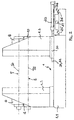
- the slitting machine comprises a frame 1 comprising a 1.1 base and a cradle-shaped upper part in U having, in the representation of FIG. 1, a vertical branch to the left 1.2 and one branch vertical right 1.3.
- Two 2.7 parallel shafts are mounted on the frame 1, between the vertical branches 1.2 and 1.3 of this frame.
- the two trees 2.7 are identical and are arranged parallel in a common vertical plane.
- each of the shafts 2.7 on the branches 1.2, 1.3 of the frame 1 is produced via long steps, with a left step 4.6 mounted on the left branch 1.2 of the frame 1 to pivot around an axis 13.15 perpendicular to the vertical plane defined by trees 2.7, and a right bearing 10.8 mounted on the right arm 1.3 of the frame 1 to pivot around an axis 14.16 perpendicular to this same plane.
- the bearings 4,6,8 and 10 have an outer casing by which they are articulated to branches 1.2 and 1.3 of the frame 2 so that a significant part of their length either overhanging the outside of these branches.
- the trees 2,7 respectively carry series of knives 17.11 in the form of discs perpendicular to the axes of these trees and separated by spacers 18.12.
- These two series of knives 17.11 carried by the trees 2.7 intersect at their periphery so as to form a series of shears capable of cutting into a plurality of strips the metal strip that passes between the two series of knives and which is thus split.
- Two thrust cylinders 9,20 are respectively mounted on right bearings 8,10 on the one hand and on the left 4,6 on the other hand. More specifically, the jack 9 has a body 9.1 hinged to the casing of the right bearing 10 of the lower shaft 2 and a rod 9.2 hinged to the outer casing of the right bearing 8 of the upper shaft 7. Similarly, the jack 20 has a body 20.1 articulated to the housing of the left bearing 4 of the lower shaft 2 and a rod 20.2 articulated to the housing of the left bearing 6 of the upper shaft 7.
- the joints of the body and the rod of each of the two jacks 9.20 define a vertical plane perpendicular to the axes of the shafts 2.7 and situated outside the U formed by the branches 1.2 and 1.3 of the frame 1, at a distance 1 from the vertical plane defined by the axes 13.15 of on the one hand and 14.16 on the other.
- This distance 1 between the articulations of the cylinders at the bearings and the articulations of the bearings at the frame constitutes a lever arm allowing the cylinders 9,20 to exert on the bearings 8,10 on the one hand and on the bearings 4,6 of on the other hand, counter-bending torques around the axes 16, 14 and 13, 15.
- the cylinders 9,20 which can be of the hydraulic type, pneumatic or electric, are controlled by a electronic unit (not shown in Figure 1).
- This electronic control unit (PLC programmable by example) controls the two cylinders 9 and 20 independently from each other, so that they exert on the right 8.10 and left 4.6 bearings different which are dynamically calculated in function of the flexural deformation of the trees to be obtained.
- the 2.7 shafts are driven by the gearmotor (not shown) via transmissions 5.19, rotating around their own axes in direction inverses of each other.
- the knife series 17.11 which are integral with these trees also rotate in opposite to each other like the rollers of a rolling mill.
- a metal strip to be split is engaged between the two sets of knives 17,11 following its direction longitudinal.
- the shears formed by the crossing of two sets of knives 17,11 cut metal strip into a plurality of strips along the longitudinal direction of the strip.
- this bending is compensated in the following manner.
- the electronic control unit supplies the cylinders 9,20 at a determined pressure so that they exert a thrust force between the left bearings 4.6 on the one hand and right bearings 8.10 on the other.
- These thrust forces translate due to the lever arm 1 between the axes of articulations of the cylinders to the bearings and the articulation axes 13,14,15,16 of the bearings to the frame 1, by a torque against bending which tends rotating the bearings 4,6,8,10 to return them to their normal horizontal position corresponding to a rectilinear geometry of the shafts 2,7.
- the supply pressure of the cylinders 9,20 is predetermined according to the different parameters of the slitting and can then be adjusted dynamically, up or down, depending on the observed deformation of the shafts 2,7.
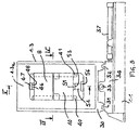
- the frame 1 has on the base 1.1 two cages 1.2 and 1.3 of which one 1.2 is fixed and the other 1.3 movable by on the other hand, in the direction of trees 2 and 7 and on the other hand, perpendicular to this direction.
- the cage 1.3 is mounted on a carriage 30 which can circulate on rails 31, 32, parallel to shafts 2 and 7, thanks to a actuating cylinder 33. It is thus possible to identify the right end (in Figure 2) of the trees their bearings 8, 10 carried by the cage 1.3.
- the cart 30 is then supported by a table 34 mounted on rails 35, 36 integral with the base 1.1 and perpendicular to the rails 31, 32.
- a jack 37 ensures the movement of the table 34 on these rails, which allows to retract laterally the cage 1.3 relative to the trees 2 and 7 and thus access the knives to change them.
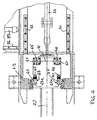
- each bearing 6 and 8 of the upper shaft 7 is mounted in the following manner.
- the corresponding cage (for example cage 1.3) is provided with two vertical rules 40, 41 introduced into lateral grooves 42, 43 of each casing. Biasing means 44, 45 hold the side 42 a, 43 a of each groove in firm contact with the face of the corresponding rule facing the shafts 2 and 7.
- the upper bearings 6 and 8 are also fitted in upper part 'A part 46 which bears on a pad 47 carried by the upper cross member of the corresponding cage (1.3 a for the cage 1.3).
- the bearing surface 48 of the parts 46 and 47 is a cylindrical surface with a horizontal axis 49 perpendicular to the axis 50 of the upper shaft 7 (axis of the bearing 8) and which intersects it.
- the bearings 6 and 8 are also kept fixed in the corresponding cage by means not shown preventing them from sliding down under the effect of gravity along the rules 40, 41.
- the lower bearings 4 and 10 cooperate from the same way as the upper levels with the rules 40, 41. These bearings are in the lower part equipped with a part such as 51 for the bearing 10, which rests on a bearing 52 with a contact surface as a contact surface cylindrical 53 with axis 54 parallel to axis 49 and intersecting the axis 55 of the bearings 4 and 10 (merged with the axis of the lower shaft 2).
- Each pad 52 supporting each lower bearing is itself carried by a jack hydraulic 56 which allows to adjust the position of the shaft 2 compared to that of shaft 7 and thus adjust the value of crossing knives. Maintaining the position of the shaft 2 is ensured by a control of the supply / exhaust of each jack 56 incorporating a position sensor not shown.
- each bearing 4, 6, 8 and 10 have a parallelepiped shape so that the lower bearings 4, 10 have a substantially face flat and horizontal opposite a similar face of upper levels 6 and 8.
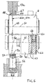
- the housings are fitted with small hydraulic cylinders (60, 61 for bearing 10) whose body is inserted under cartridge shape in the housings where the supply and exhaust channels 62 and 63 of each cylinder.
- the rod 64, 65 of each cylinder is in the state retracted retracted to surface level upper of the corresponding bearing housing while by its extension it comes to rest on the surface bottom of the housing of each upper bearing.
- the synchronized supply of the jacks 60, 61 causes the bearings to rotate about the axes 49 and 54 respectively, rotation allowed by an appropriate shape of the profile of the sides 42 a and 43 has grooves 42 and 43 of each casing (see FIG. 5) which can thus slide slightly on the rules 40, 41.
- This forced pivoting causes, as previously described with reference to FIG. 1, a counter-bending of the shafts 2 and 7 towards each other coming to counter the bending generated by the cutting. sheets during their slitting.
Landscapes
- Engineering & Computer Science (AREA)
- Mechanical Engineering (AREA)
- Life Sciences & Earth Sciences (AREA)
- Forests & Forestry (AREA)
- Bending Of Plates, Rods, And Pipes (AREA)
- Load-Engaging Elements For Cranes (AREA)
- Perforating, Stamping-Out Or Severing By Means Other Than Cutting (AREA)
- Shearing Machines (AREA)
- Debarking, Splitting, And Disintegration Of Timber (AREA)
- Accessories And Tools For Shearing Machines (AREA)
Claims (6)
- Streifenschneidemaschine, umfassend ein Gestell (1), an dem jeweils mittels zweier Längslager (4, 10, 6, 8) zwei parallele Wellen (2, 7) gelagert sind, die durch Antriebsmittel (5) in Drehrichtung angetrieben werden und jeweils eine Reihe von Schneidmessern (11, 17) in Form von Scheiben tragen, die in senkrecht zu den genannten Wellen verlaufenden Ebenen angeordnet sind und an ihrem Umfang die Reihe von Schneidmessem der anderen Welle kreuzen, um eine Reihe von Scheren zu bilden, wobei die Maschine mit mechanischen Mitteln versehen ist, um mindestens einer der Wellen eine Gegenbiegung in Richtung der anderen zu verleihen, um die während des Schneidens hervorgerufene Biegung auszugleichen, die darauf abzielt, die Schneidmesser der einen Welle von den Schneidmessern der anderen Welle zu entfernen, dadurch gekennzeichnet, daß jedes der Längslager (4, 10, 6, 8) derart am Gestell (1) gelagert ist, daß es um eine Achse (13, 14, 15, 16) schwenkt, die senkrecht zu der Ebene verläuft, die von den beiden Wellen (2, 7) festgelegt wird, und daß die obengenannten mechanischen Mittel mindestens einen Zylinder (9, 20) umfassen, der darauf abzielt, jedes Lager um dessen Schwenkachse zur Drehung zu bringen.
- Maschine nach Anspruch 1, dadurch gekennzeichnet, daß ihr Gestell zwei Ständer (1.2, 1.3) umfaßt, zwischen denen sich die Wellen (2, 7) mit Schneidmessern erstrecken und in denen jeweils ein Endlager (4, 6, 8, 10) jeder Welle (2, 7) an einer zylindrischen Auflagefläche (48, 53) des Ständers gelagert ist, deren Achse (49, 54) die Achse (50, 55) der entsprechenden Welle senkrecht schneidet, und daß der obengenannte Zylinder (60, 61) zwischen den beiden Lagern (8, 10) angeordnet ist, auf der den Messerwellen (2, 7) abgewandten Seite des Ständers (1.3).
- Maschine nach Anspruch 2, dadurch gekennzeichnet, daß das Gehäuse des Zylinders (60, 61) einen Einsatz bildet, der in das Gehäuse eines der Lager (10) eingesetzt wird, während seine Stange (64) mittels einfacher Auflage mit dem Gehäuse des anderen Lagers (8) zusammenwirkt.
- Maschine nach Anspruch 3, dadurch gekennzeichnet, daß sie zwischen den beiden von einem Ständer (1.3) getragenen Lagern (8, 10) zwei Zylinder (60, 61) umfaßt.
- Maschine nach Anspruch 4, dadurch gekennzeichnet, daß sie zwischen den beiden von dem anderen Ständer (1.2) getragenen Lagern zwei Zylinder umfaßt.
- Maschine nach Anspruch 4, dadurch gekennzeichnet, daß die Zylinderpaare (60, 61) unabhängig voneinander gesteuert werden.
Applications Claiming Priority (2)
| Application Number | Priority Date | Filing Date | Title |
|---|---|---|---|
| FR9909711A FR2796877B1 (fr) | 1999-07-27 | 1999-07-27 | Machine de refendage a fleche compensee |
| FR9909711 | 1999-07-27 |
Publications (2)
| Publication Number | Publication Date |
|---|---|
| EP1086768A1 EP1086768A1 (de) | 2001-03-28 |
| EP1086768B1 true EP1086768B1 (de) | 2003-09-03 |
Family
ID=9548550
Family Applications (1)
| Application Number | Title | Priority Date | Filing Date |
|---|---|---|---|
| EP00402150A Expired - Lifetime EP1086768B1 (de) | 1999-07-27 | 2000-07-27 | Streifenschere mit kompensierter Durchbiegung |
Country Status (4)
| Country | Link |
|---|---|
| EP (1) | EP1086768B1 (de) |
| AT (1) | ATE248680T1 (de) |
| DE (1) | DE60004939T2 (de) |
| FR (1) | FR2796877B1 (de) |
Families Citing this family (2)
| Publication number | Priority date | Publication date | Assignee | Title |
|---|---|---|---|---|
| CN114434535A (zh) * | 2022-01-25 | 2022-05-06 | 浙江荣晟环保纸业股份有限公司 | 一种箱纸板造纸设备用的分切装置 |
| CN118287740A (zh) * | 2024-04-12 | 2024-07-05 | 二重(德阳)重型装备有限公司 | 一种圆盘剪装置 |
Family Cites Families (2)
| Publication number | Priority date | Publication date | Assignee | Title |
|---|---|---|---|---|
| ATE52954T1 (de) * | 1987-04-23 | 1990-06-15 | Schloemann Siemag Ag | Laengsteil-streifenschere. |
| FR2651456A1 (fr) * | 1989-09-05 | 1991-03-08 | Ugine Aciers | Dispositif de cisaillage-refendage circulaire a froid de toles. |
-
1999
- 1999-07-27 FR FR9909711A patent/FR2796877B1/fr not_active Expired - Fee Related
-
2000
- 2000-07-27 AT AT00402150T patent/ATE248680T1/de not_active IP Right Cessation
- 2000-07-27 EP EP00402150A patent/EP1086768B1/de not_active Expired - Lifetime
- 2000-07-27 DE DE60004939T patent/DE60004939T2/de not_active Expired - Lifetime
Also Published As
| Publication number | Publication date |
|---|---|
| ATE248680T1 (de) | 2003-09-15 |
| DE60004939T2 (de) | 2004-07-15 |
| FR2796877B1 (fr) | 2001-09-07 |
| DE60004939D1 (de) | 2003-10-09 |
| FR2796877A1 (fr) | 2001-02-02 |
| EP1086768A1 (de) | 2001-03-28 |
Similar Documents
| Publication | Publication Date | Title |
|---|---|---|
| EP2177292B1 (de) | Vorrichtung zum Richten und Zuführen von einem halbstarren Materialstreifen in eine Maschine | |
| EP2964436B1 (de) | Regulierbare anordnung zur umwandlung einer ebenen halterung, kassette, einheit und damit ausgestattete maschine | |
| CA2122333C (fr) | Installation de positionnement bord a bord et de soudage au moyen d'un faisceau laser d'au moins deux flans de tole | |
| FR2840844A1 (fr) | Disque couper a plongee rotative avec contre-partie rainuree de style a griffe | |
| WO2010097100A1 (fr) | Procede de modification de la distance entre les rouleaux d'une machine de planage, machine et installation de planage pour la mise en oeuvre dudit procede | |
| EP3530404B1 (de) | Vorrichtung und verfahren zur bearbeitung einer extremität eines grundpaneels als vorbereitung auf seine bearbeitung durch reibrührschweissverfahren | |
| EP0707902B1 (de) | Walzanlage | |
| EP0547954B1 (de) | Rotationsstanzvorrichtung | |
| FR2475365A1 (fr) | Dispositif de rognage de la charge de tabac pour machine a fabriquer les cigarettes | |
| EP1005923B1 (de) | Walzwerk mit Mitteln zur Biegung der Arbeitswalzen | |
| EP1086768A1 (de) | Streifenschere mit kompensierter Durchbiegung | |
| FR2513608A1 (fr) | Appareil de manutention de feuilles minces de materiau | |
| FR2462241A1 (fr) | Dispositif de coupe a matrice rotative | |
| FR2550486A1 (fr) | Machine de coupe a disques a commande numerique et procede de reglage de ses ensembles de coupe | |
| EP1982937A1 (de) | Transportvorrichtung für eine Leim- und Faltmaschine | |
| EP2035164B1 (de) | Vorrichtung und verfahren zur verbindung zweier bleche durch crimping | |
| EP0368686B1 (de) | Automatisierbare Rundwalzeneinrichtung mit verzahnten Walzen | |
| FR2740943A1 (fr) | Machine a grigner | |
| FR2600919A1 (fr) | Procede et dispositif pour la retouche due a l'usure des cylindres d'un laminoir, sur la ligne de laminage | |
| EP0225198A1 (de) | Vorrichtung zum Streckrichten eines metallischen Bandes | |
| EP1749603A1 (de) | Vorrichtung zum Längsteilen von dünnen Bändern | |
| EP1719591A1 (de) | Verfahren zum Bearbeiten von Bahn- oder Blattförmigen Materialien sowie Presse zur Ausführung des Verfahrens | |
| FR2847836A1 (fr) | Dispositif de presse multifonction | |
| FR2465572A1 (en) | Machine for slitting roll of fabric - has mechanism for advancing rotating roll towards rotating circular blade | |
| FR2539338A1 (fr) | Laminoir a dispositif de controle de planeite |
Legal Events
| Date | Code | Title | Description |
|---|---|---|---|
| PUAI | Public reference made under article 153(3) epc to a published international application that has entered the european phase |
Free format text: ORIGINAL CODE: 0009012 |
|
| AK | Designated contracting states |
Kind code of ref document: A1 Designated state(s): AT BE CH CY DE DK ES FI FR GB GR IE IT LI LU MC NL PT SE |
|
| AX | Request for extension of the european patent |
Free format text: AL;LT;LV;MK;RO;SI |
|
| 17P | Request for examination filed |
Effective date: 20010705 |
|
| AKX | Designation fees paid |
Free format text: AT BE CH CY DE DK ES FI FR GB GR IE IT LI LU MC NL PT SE |
|
| 17Q | First examination report despatched |
Effective date: 20030108 |
|
| GRAH | Despatch of communication of intention to grant a patent |
Free format text: ORIGINAL CODE: EPIDOS IGRA |
|
| GRAH | Despatch of communication of intention to grant a patent |
Free format text: ORIGINAL CODE: EPIDOS IGRA |
|
| GRAA | (expected) grant |
Free format text: ORIGINAL CODE: 0009210 |
|
| AK | Designated contracting states |
Kind code of ref document: B1 Designated state(s): AT BE CH CY DE DK ES FI FR GB GR IE IT LI LU MC NL PT SE |
|
| PG25 | Lapsed in a contracting state [announced via postgrant information from national office to epo] |
Ref country code: AT Free format text: LAPSE BECAUSE OF FAILURE TO SUBMIT A TRANSLATION OF THE DESCRIPTION OR TO PAY THE FEE WITHIN THE PRESCRIBED TIME-LIMIT Effective date: 20030903 Ref country code: NL Free format text: LAPSE BECAUSE OF FAILURE TO SUBMIT A TRANSLATION OF THE DESCRIPTION OR TO PAY THE FEE WITHIN THE PRESCRIBED TIME-LIMIT Effective date: 20030903 Ref country code: IE Free format text: LAPSE BECAUSE OF FAILURE TO SUBMIT A TRANSLATION OF THE DESCRIPTION OR TO PAY THE FEE WITHIN THE PRESCRIBED TIME-LIMIT Effective date: 20030903 Ref country code: FI Free format text: LAPSE BECAUSE OF FAILURE TO SUBMIT A TRANSLATION OF THE DESCRIPTION OR TO PAY THE FEE WITHIN THE PRESCRIBED TIME-LIMIT Effective date: 20030903 Ref country code: CY Free format text: LAPSE BECAUSE OF FAILURE TO SUBMIT A TRANSLATION OF THE DESCRIPTION OR TO PAY THE FEE WITHIN THE PRESCRIBED TIME-LIMIT Effective date: 20030903 Ref country code: GB Free format text: LAPSE BECAUSE OF FAILURE TO SUBMIT A TRANSLATION OF THE DESCRIPTION OR TO PAY THE FEE WITHIN THE PRESCRIBED TIME-LIMIT Effective date: 20030903 |
|
| REG | Reference to a national code |
Ref country code: GB Ref legal event code: FG4D Free format text: NOT ENGLISH |
|
| RIN1 | Information on inventor provided before grant (corrected) |
Inventor name: COULMONT, JEAN-PIERRE Inventor name: LARDE, ALAIN Inventor name: CZTERNASTEK, FRANCIS |
|
| REG | Reference to a national code |
Ref country code: CH Ref legal event code: EP Ref country code: CH Ref legal event code: NV Representative=s name: BOVARD AG PATENTANWAELTE |
|
| REF | Corresponds to: |
Ref document number: 60004939 Country of ref document: DE Date of ref document: 20031009 Kind code of ref document: P |
|
| REG | Reference to a national code |
Ref country code: IE Ref legal event code: FG4D Free format text: FRENCH |
|
| PG25 | Lapsed in a contracting state [announced via postgrant information from national office to epo] |
Ref country code: SE Free format text: LAPSE BECAUSE OF FAILURE TO SUBMIT A TRANSLATION OF THE DESCRIPTION OR TO PAY THE FEE WITHIN THE PRESCRIBED TIME-LIMIT Effective date: 20031203 Ref country code: DK Free format text: LAPSE BECAUSE OF FAILURE TO SUBMIT A TRANSLATION OF THE DESCRIPTION OR TO PAY THE FEE WITHIN THE PRESCRIBED TIME-LIMIT Effective date: 20031203 Ref country code: GR Free format text: LAPSE BECAUSE OF FAILURE TO SUBMIT A TRANSLATION OF THE DESCRIPTION OR TO PAY THE FEE WITHIN THE PRESCRIBED TIME-LIMIT Effective date: 20031203 |
|
| PG25 | Lapsed in a contracting state [announced via postgrant information from national office to epo] |
Ref country code: ES Free format text: LAPSE BECAUSE OF FAILURE TO SUBMIT A TRANSLATION OF THE DESCRIPTION OR TO PAY THE FEE WITHIN THE PRESCRIBED TIME-LIMIT Effective date: 20031214 |
|
| NLV1 | Nl: lapsed or annulled due to failure to fulfill the requirements of art. 29p and 29m of the patents act | ||
| PG25 | Lapsed in a contracting state [announced via postgrant information from national office to epo] |
Ref country code: PT Free format text: LAPSE BECAUSE OF FAILURE TO SUBMIT A TRANSLATION OF THE DESCRIPTION OR TO PAY THE FEE WITHIN THE PRESCRIBED TIME-LIMIT Effective date: 20040203 |
|
| GBV | Gb: ep patent (uk) treated as always having been void in accordance with gb section 77(7)/1977 [no translation filed] |
Effective date: 20030903 |
|
| REG | Reference to a national code |
Ref country code: IE Ref legal event code: FD4D |
|
| PLBE | No opposition filed within time limit |
Free format text: ORIGINAL CODE: 0009261 |
|
| STAA | Information on the status of an ep patent application or granted ep patent |
Free format text: STATUS: NO OPPOSITION FILED WITHIN TIME LIMIT |
|
| PG25 | Lapsed in a contracting state [announced via postgrant information from national office to epo] |
Ref country code: LU Free format text: LAPSE BECAUSE OF NON-PAYMENT OF DUE FEES Effective date: 20040727 |
|
| PG25 | Lapsed in a contracting state [announced via postgrant information from national office to epo] |
Ref country code: MC Free format text: LAPSE BECAUSE OF NON-PAYMENT OF DUE FEES Effective date: 20040731 Ref country code: BE Free format text: LAPSE BECAUSE OF NON-PAYMENT OF DUE FEES Effective date: 20040731 |
|
| 26N | No opposition filed |
Effective date: 20040604 |
|
| BERE | Be: lapsed |
Owner name: *REDEX Effective date: 20040731 |
|
| BERE | Be: lapsed |
Owner name: *REDEX Effective date: 20040731 |
|
| REG | Reference to a national code |
Ref country code: CH Ref legal event code: PFA Owner name: REDEX Free format text: REDEX#ZONE INDUSTRIELLE#45210 FERRIERES (FR) -TRANSFER TO- REDEX#ZONE INDUSTRIELLE#45210 FERRIERES (FR) |
|
| PGFP | Annual fee paid to national office [announced via postgrant information from national office to epo] |
Ref country code: DE Payment date: 20140721 Year of fee payment: 15 Ref country code: CH Payment date: 20140721 Year of fee payment: 15 |
|
| PGFP | Annual fee paid to national office [announced via postgrant information from national office to epo] |
Ref country code: FR Payment date: 20140721 Year of fee payment: 15 |
|
| PGFP | Annual fee paid to national office [announced via postgrant information from national office to epo] |
Ref country code: IT Payment date: 20140729 Year of fee payment: 15 |
|
| REG | Reference to a national code |
Ref country code: DE Ref legal event code: R082 Ref document number: 60004939 Country of ref document: DE Representative=s name: SCHAUMBURG & PARTNER PATENTANWAELTE GBR, DE Ref country code: DE Ref legal event code: R082 Ref document number: 60004939 Country of ref document: DE Representative=s name: SCHAUMBURG & PARTNER PATENTANWAELTE MBB, DE Ref country code: DE Ref legal event code: R082 Ref document number: 60004939 Country of ref document: DE Representative=s name: SCHAUMBURG UND PARTNER PATENTANWAELTE MBB, DE |
|
| REG | Reference to a national code |
Ref country code: DE Ref legal event code: R119 Ref document number: 60004939 Country of ref document: DE |
|
| REG | Reference to a national code |
Ref country code: CH Ref legal event code: PL |
|
| PG25 | Lapsed in a contracting state [announced via postgrant information from national office to epo] |
Ref country code: LI Free format text: LAPSE BECAUSE OF NON-PAYMENT OF DUE FEES Effective date: 20150731 Ref country code: IT Free format text: LAPSE BECAUSE OF NON-PAYMENT OF DUE FEES Effective date: 20150727 Ref country code: CH Free format text: LAPSE BECAUSE OF NON-PAYMENT OF DUE FEES Effective date: 20150731 Ref country code: DE Free format text: LAPSE BECAUSE OF NON-PAYMENT OF DUE FEES Effective date: 20160202 |
|
| REG | Reference to a national code |
Ref country code: FR Ref legal event code: ST Effective date: 20160331 |
|
| PG25 | Lapsed in a contracting state [announced via postgrant information from national office to epo] |
Ref country code: FR Free format text: LAPSE BECAUSE OF NON-PAYMENT OF DUE FEES Effective date: 20150731 |