EP1086785A2 - Outil actionne par fluide - Google Patents
Outil actionne par fluide Download PDFInfo
- Publication number
- EP1086785A2 EP1086785A2 EP00123942A EP00123942A EP1086785A2 EP 1086785 A2 EP1086785 A2 EP 1086785A2 EP 00123942 A EP00123942 A EP 00123942A EP 00123942 A EP00123942 A EP 00123942A EP 1086785 A2 EP1086785 A2 EP 1086785A2
- Authority
- EP
- European Patent Office
- Prior art keywords
- piston
- fluid
- cylinder
- link
- housing
- Prior art date
- Legal status (The legal status is an assumption and is not a legal conclusion. Google has not performed a legal analysis and makes no representation as to the accuracy of the status listed.)
- Granted
Links
Images
Classifications
-
- B—PERFORMING OPERATIONS; TRANSPORTING
- B25—HAND TOOLS; PORTABLE POWER-DRIVEN TOOLS; MANIPULATORS
- B25B—TOOLS OR BENCH DEVICES NOT OTHERWISE PROVIDED FOR, FOR FASTENING, CONNECTING, DISENGAGING, OR HOLDING
- B25B21/00—Portable power-driven screw or nut setting or loosening tools; Attachments for drilling apparatus serving the same purpose
- B25B21/004—Portable power-driven screw or nut setting or loosening tools; Attachments for drilling apparatus serving the same purpose of the ratchet type
- B25B21/005—Portable power-driven screw or nut setting or loosening tools; Attachments for drilling apparatus serving the same purpose of the ratchet type driven by a radially acting hydraulic or pneumatic piston
-
- B—PERFORMING OPERATIONS; TRANSPORTING
- B25—HAND TOOLS; PORTABLE POWER-DRIVEN TOOLS; MANIPULATORS
- B25B—TOOLS OR BENCH DEVICES NOT OTHERWISE PROVIDED FOR, FOR FASTENING, CONNECTING, DISENGAGING, OR HOLDING
- B25B23/00—Details of, or accessories for, spanners, wrenches, screwdrivers
- B25B23/0078—Reaction arms
Definitions
- This invention relates to a fluid-operated tool for tightening or loosening a threaded connector.
- Fluid-operated tools are well known and widely used in industry. If a space in which to apply the tool is narrow, limited clearance fluid-operated tools can be utilized. These limited clearance tools have links which carry a threaded connector engaging element and which are connected with the tool housing to be turned by a drive arranged in the housing. In order to obtain the desired torque accuracy during tightening and loosening, it is important that the housing pivots around an axis of the engaging element or the threaded connector engaged by it.
- the housing of known tools is provided with side plates and the links, which usually include two drive plates and a ratchet pivotable in them, is sandwiched between the side plates. The side plates can either be a part of the housing or be steadily connected to the housing.
- US-A-2,972,918 and US-A-3,706,244 each disclose prior art fluid-operated tools for tightening or loosening threaded connectors. Both these prior art tools operate with a single cylinder-piston unit.
- the fluid-operated cylinder-piston means includes two cylinder-piston units.
- the fluid-operated cylinder-piston means has two cylinders, two pistons each reciprocatingly movable in a respective one of the cylinders and each having a connecting rod connected to the link means so that the connecting rods are connected with the link means at two points radially spaced from the pivot axis of the engaging element and from one another, the points of connection of the piston rods to the link means turning about the pivot axis by the same angle in response to displacement by the piston rods.
- a high torque accuracy is provided in addition to the reduction of the thickness of the engaging part of the tool.
- the housing means is connected with the link means so that under the action of a reaction force acting on the housing means, during tightening and/or loosening of a threaded connector, the housing means or at least a part of it can pivot relative to the link means.
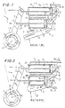
- Figure 1 shows a fluid-operated tool in accordance with the present invention including link means generally designated by the reference numeral 1.
- the link means 1 comprises two spaced apart levers or links 2 having circular openings therein, a ratchet 3 turnably received in the openings of the links 2 and having a portion located between the links 2 and provided with a plurality of teeth, and a pawl 4 arranged between the links 2 and having teeth engagable with the teeth of the ratchet 3.
- Such a construction is known in the art, as disclosed for example in my U.S. patents US-A-4,368,655 and US-A-4,706,527.
- the ratchet 3 forms an engaging element of the tool for engaging a threaded connector, for example a nut.
- the engaging element has a nut-engaging inner polygonal opening and is turnable about a pivot axis A for turning the nut.
- the fluid-operated tool further includes a housing, generally designated 5, having two housing parts 6 and 7.
- a fluid-operated drive, generally designated 8, is provided to pivot the link means 1 about the pivot axis A.
- the fluid-operated drive 8 includes two cylinder-piston units 9 and 10.
- the cylinder-piston unit 9 has a cylinder 11 formed by the housing part 6, a piston 12 reciprocatingly movable in the cylinder 11, and a piston rod 13 connected with the piston 12 and extending outwardly of the cylinder 11.
- the cylinder-piston unit 10 has a cylinder 14 formed in the housing part 7, a piston 15 reciprocatingly movable in the cylinder 14, and a piston rod 16 connected with the piston 15 and extending outwardly of the cylinder 14.
- the piston rod 13 of the cylinder-piston unit 9 is pivotably connected with the links 2 at a pivot point B, while the piston rod 16 of the cylinder-piston unit 10 is pivotably connected with the links 2 at a pivot point C.
- the cylinder 11 of the cylinder-piston unit 9 has a fluid inlet port 17 in its piston chamber and a fluid outlet port 18 in its piston rod chamber, whereas the cylinder 14 of the cylinder-piston unit 10 has a fluid inlet port 19 in its piston chamber and a fluid outlet port 20 in its piston rod chamber.
- a fluid connection connects the ports 18 and 19.
- the fluid-operated tool also has reaction means, generally designated 21, formed as a reaction member or plate 22 having one portion formed to abut against a neighbouring object, for example a nut, a bolt or the like, and another portion connected to the housing 5. More particularly, the other portion of the reaction plate 22 is pivotably connected to the housing parts 6 and 7 at pivot points D and E, for example by pivot pins extending through openings in the reaction plate 22 and corresponding projecting portions of the housing portions 6 and 7.
- the links 2 and ratchet 3 are positioned so that the polygonal opening of the ratchet 3 is fitted on a threaded connector, for example a nut.
- Pressure fluid is supplied through the port 17 into the piston chamber of the cylinder-piston unit 9 and displaces the piston 12 and piston rod 13 to the left, in Figure 1, so that the piston rod 13 displaces the pivot point B of the link means 1 through a counter-clockwise arc.
- pressure fluid is discharged through the port 18 and is supplied through the port 19 into the piston chamber of the cylinder-piston unit 10.
- the piston 15 and piston rod 16 move to the left and the pressure fluid is discharged through the port 20.
- the links 2 pivotally turn around the pivot axis A and turn the pawl 4 which turns the ratchet 3 and as a result turns the nut engaged in the ratchet. Since the cylinder-piston units 9 and 10 are in communication with one another, and because of the design of their cylinders, chambers, pistons, and piston rods, the pivot points B and C of the lever means 1 are pivoted around the pivot axis A by the same angle, despite the fact that the piston rods 13 and 16 perform strokes of different lengths.
- reaction force which is created during the forward stroke and which urges the housing portions 6 and 7 to move in directions opposite to the active stroke of their cylinder-piston units, is counteracted by the reaction plate 22 which abuts against a neighbouring object, such as for example a neighbouring nut or the like. Since, during the advance stroke, the piston rod 13 of the cylinder-piston unit 9 is pushed to the left by the fluid while the piston rod 16 of the cylinder-piston unit 10 is pulled, reaction forces act in opposite directions.
- reaction plate 22 is pivotably connected with the housing 6, 7 or the cylinders 9, 10, the reaction force pushes the cylinder 14 of the cylinder-piston unit 10 toward the front and pushes the cylinder 11 of the cylinder-piston unit 9 toward the rear.
- the pressure fluid is supplied in an opposite direction and firstly flows into the lower cylinder-piston unit 10 and then flows into the upper cylinder-piston unit 9.
- the piston rods 16 and 13 are thus displaced in an opposite direction and therefore turn the link means 1 in the opposite direction so as to turn the threaded connection in an opposite direction.
- the fluid-operated tool shown in Figure 2 is substantially similar to the fluid-operated tool shown in Figure 1.
- a reaction means 21' is formed as a reaction plate 22' which is fixedly connected to the lower housing portion 7 or the lower cylinder 14.
- a separate element 23 pivotably connects the housing portions 6, 7 or the cylinders 11, 14 of the cylinder-piston units 9 and 10 with one another.
- a fluid inlet port 24 and a fluid outlet port 25 of the cylinder-piston unit 10 are located in the piston chamber and the piston rod chamber, respectively.
- a fluid-inlet port 26 and a fluid outlet port 27 of the cylinder-piston unit 9 are arranged in the piston chamber and the piston rod chamber of the cylinder 11, respectively.
- the fluid is supplied into the cylinder-piston unit 10 to push the piston rod 16, while the piston rod 13 is pulled by the link means 1.
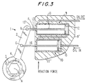
- the fluid-operated tool of Figure 3 is substantially analogous to the fluid-operated tool of Figure 1.
- housing 5' is formed as an integral housing containing both cylinders 11 and 14 of the cylinder-piston units 9 and 10. While the piston rod 16 of the cylinder-piston unit 10 is connected directly to the pivot point C of the link means 1, the piston rod 13 of the cylinder-piston unit 9 is connected with the pivot point B of the link means 1 pivotably about a pivot point F.
- the piston rod 13 has two portions 13' and 13" pivotally connected together with portion 13' connected to the piston 12 and portion 13" connected to the link means 1. This allows the housing 5 to turn relative to the link means 1 about the point F in response to different reaction forces acting on the cylinder-piston units and different strokes of the piston rods.
- the reaction means 22" is formed by a part of the housing 5'.
Landscapes
- Engineering & Computer Science (AREA)
- Mechanical Engineering (AREA)
- Jigs For Machine Tools (AREA)
- Actuator (AREA)
- Pens And Brushes (AREA)
- Steering Control In Accordance With Driving Conditions (AREA)
- Earth Drilling (AREA)
- Manipulator (AREA)
- Manufacturing Of Electrical Connectors (AREA)
Applications Claiming Priority (3)
| Application Number | Priority Date | Filing Date | Title |
|---|---|---|---|
| US36848 | 1998-03-09 | ||
| US09/036,848 US6105472A (en) | 1998-03-09 | 1998-03-09 | Fluid-operated tool |
| EP99300407A EP0941810A3 (fr) | 1998-03-09 | 1999-01-20 | Outil actionné par fluide sous pression |
Related Parent Applications (1)
| Application Number | Title | Priority Date | Filing Date |
|---|---|---|---|
| EP99300407A Division EP0941810A3 (fr) | 1998-03-09 | 1999-01-20 | Outil actionné par fluide sous pression |
Publications (3)
| Publication Number | Publication Date |
|---|---|
| EP1086785A2 true EP1086785A2 (fr) | 2001-03-28 |
| EP1086785A3 EP1086785A3 (fr) | 2002-04-17 |
| EP1086785B1 EP1086785B1 (fr) | 2005-12-07 |
Family
ID=21890992
Family Applications (2)
| Application Number | Title | Priority Date | Filing Date |
|---|---|---|---|
| EP99300407A Withdrawn EP0941810A3 (fr) | 1998-03-09 | 1999-01-20 | Outil actionné par fluide sous pression |
| EP00123942A Expired - Lifetime EP1086785B1 (fr) | 1998-03-09 | 1999-01-20 | Outil actionne par fluide |
Family Applications Before (1)
| Application Number | Title | Priority Date | Filing Date |
|---|---|---|---|
| EP99300407A Withdrawn EP0941810A3 (fr) | 1998-03-09 | 1999-01-20 | Outil actionné par fluide sous pression |
Country Status (4)
| Country | Link |
|---|---|
| US (1) | US6105472A (fr) |
| EP (2) | EP0941810A3 (fr) |
| AT (1) | ATE311960T1 (fr) |
| DE (1) | DE69928800D1 (fr) |
Families Citing this family (6)
| Publication number | Priority date | Publication date | Assignee | Title |
|---|---|---|---|---|
| US20040225604A1 (en) * | 2003-04-29 | 2004-11-11 | Foss Sheldon H. | System for providing a checkless checking account |
| US20140260816A1 (en) * | 2013-03-14 | 2014-09-18 | William Frank Budleski | Opposing force tool drive system |
| CN104723083B (zh) * | 2015-03-27 | 2017-03-01 | 苏州市吴中区木渎华利模具加工店 | 铝合金关节连接器组装机的螺母拧紧装置 |
| ES2927807T3 (es) | 2015-10-05 | 2022-11-11 | Hytorc Division Unex Corp | Aparato para apretar sujetadores roscados |
| CN113560865B (zh) * | 2021-08-25 | 2022-04-26 | 河北省科学院应用数学研究所 | 无源式机械旋拧装置 |
| US20240082993A1 (en) * | 2022-09-09 | 2024-03-14 | Joy Global Surface Mining Inc | Service tool |
Family Cites Families (7)
| Publication number | Priority date | Publication date | Assignee | Title |
|---|---|---|---|---|
| CH165226A (de) * | 1932-04-01 | 1933-11-15 | Juchli Helen | Schraubenschlüssel mit motorischem Antrieb. |
| US2729997A (en) * | 1954-07-06 | 1956-01-10 | Kell Strom Tool Co Inc | Hydraulically controlled reversible ratchet wrench |
| US2972918A (en) * | 1959-05-27 | 1961-02-28 | Texaco Inc | Device for use with a fluid pressure actuated wrench |
| US3706244A (en) * | 1971-03-01 | 1972-12-19 | Nsw Corp | Wrenching apparatus and method |
| DE3323904A1 (de) * | 1983-07-02 | 1985-01-10 | Paul-Heinz 5203 Much Wagner | Drehwerkzeug |
| US4669338A (en) * | 1985-10-11 | 1987-06-02 | Collins Bobby W | Ratcheting box wrench |
| US4916986A (en) * | 1988-05-19 | 1990-04-17 | Junkers John K | Fluid operated wrench |
-
1998
- 1998-03-09 US US09/036,848 patent/US6105472A/en not_active Expired - Fee Related
-
1999
- 1999-01-20 DE DE69928800T patent/DE69928800D1/de not_active Expired - Lifetime
- 1999-01-20 EP EP99300407A patent/EP0941810A3/fr not_active Withdrawn
- 1999-01-20 EP EP00123942A patent/EP1086785B1/fr not_active Expired - Lifetime
- 1999-01-20 AT AT00123942T patent/ATE311960T1/de not_active IP Right Cessation
Also Published As
| Publication number | Publication date |
|---|---|
| US6105472A (en) | 2000-08-22 |
| EP1086785A3 (fr) | 2002-04-17 |
| ATE311960T1 (de) | 2005-12-15 |
| EP0941810A3 (fr) | 2000-08-02 |
| DE69928800D1 (de) | 2006-01-12 |
| EP0941810A2 (fr) | 1999-09-15 |
| EP1086785B1 (fr) | 2005-12-07 |
Similar Documents
| Publication | Publication Date | Title |
|---|---|---|
| US4825730A (en) | Fluid operated wrench | |
| EP1063060B1 (fr) | Outil motorisé | |
| US4409865A (en) | Continuous ratchet drive | |
| USRE33951E (en) | Fluid operated wrench | |
| EP1086785B1 (fr) | Outil actionne par fluide | |
| EP0953411B1 (fr) | Outil actionné par fluide | |
| US4446762A (en) | Universally usable hydraulic wrench for simultaneously tightening or loosening two threaded connectors or for tightening or loosening a single threaded connector with a greater force | |
| US5016502A (en) | Power wrench | |
| EP0478760B1 (fr) | Cle dynamometrique a declenchement | |
| EP1052067B1 (fr) | Outil actionné par fluide | |
| US4387611A (en) | Hydraulic wrench for simultaneously tightening or loosening at least two threaded connectors | |
| US4406185A (en) | Universally usable hydraulic wrench for simultaneously tightening or loosening two threaded connectors | |
| US4233865A (en) | Hydraulic wrench | |
| EP0468614B1 (fr) | Connexion pivotante pour outil actionné par fluide | |
| US20020073808A1 (en) | Housing for a power tool | |
| HK1036244A (en) | Fluid-operated tool | |
| EP1296804B1 (fr) | Cle dynamometrique | |
| AU2001266144A1 (en) | Torque wrench | |
| US11618139B2 (en) | Multiplex bolting tool | |
| US4916986A (en) | Fluid operated wrench | |
| GB1562710A (en) | Hydraulic wrench | |
| JPS634619Y2 (fr) | ||
| HK1029772B (en) | Fluid-operated tool | |
| HK1020267B (en) | Fluid-operated tool | |
| JPH02232177A (ja) | 液圧作動レンチ |
Legal Events
| Date | Code | Title | Description |
|---|---|---|---|
| PUAI | Public reference made under article 153(3) epc to a published international application that has entered the european phase |
Free format text: ORIGINAL CODE: 0009012 |
|
| AC | Divisional application: reference to earlier application |
Ref document number: 941810 Country of ref document: EP |
|
| AK | Designated contracting states |
Kind code of ref document: A2 Designated state(s): AT BE CH CY DE DK ES FI FR GB GR IE IT LI LU MC NL PT SE |
|
| AX | Request for extension of the european patent |
Free format text: AL;LT;LV;MK;RO;SI |
|
| PUAL | Search report despatched |
Free format text: ORIGINAL CODE: 0009013 |
|
| AK | Designated contracting states |
Kind code of ref document: A3 Designated state(s): AT BE CH CY DE DK ES FI FR GB GR IE IT LI LU MC NL PT SE |
|
| AX | Request for extension of the european patent |
Free format text: AL;LT;LV;MK;RO;SI |
|
| 17P | Request for examination filed |
Effective date: 20020729 |
|
| AKX | Designation fees paid |
Free format text: AT BE CH CY DE DK ES FI FR GB GR IE IT LI LU MC NL PT SE |
|
| AXX | Extension fees paid |
Free format text: AL PAYMENT 20020729;LT PAYMENT 20020729;LV PAYMENT 20020729;MK PAYMENT 20020729;RO PAYMENT 20020729;SI PAYMENT 20020729 |
|
| 17Q | First examination report despatched |
Effective date: 20041001 |
|
| GRAP | Despatch of communication of intention to grant a patent |
Free format text: ORIGINAL CODE: EPIDOSNIGR1 |
|
| GRAS | Grant fee paid |
Free format text: ORIGINAL CODE: EPIDOSNIGR3 |
|
| GRAA | (expected) grant |
Free format text: ORIGINAL CODE: 0009210 |
|
| AC | Divisional application: reference to earlier application |
Ref document number: 0941810 Country of ref document: EP Kind code of ref document: P |
|
| AK | Designated contracting states |
Kind code of ref document: B1 Designated state(s): AT BE CH CY DE DK ES FI FR GB GR IE IT LI LU MC NL PT SE |
|
| AX | Request for extension of the european patent |
Extension state: AL LT LV MK RO SI |
|
| PG25 | Lapsed in a contracting state [announced via postgrant information from national office to epo] |
Ref country code: IT Free format text: LAPSE BECAUSE OF FAILURE TO SUBMIT A TRANSLATION OF THE DESCRIPTION OR TO PAY THE FEE WITHIN THE PRESCRIBED TIME-LIMIT;WARNING: LAPSES OF ITALIAN PATENTS WITH EFFECTIVE DATE BEFORE 2007 MAY HAVE OCCURRED AT ANY TIME BEFORE 2007. THE CORRECT EFFECTIVE DATE MAY BE DIFFERENT FROM THE ONE RECORDED. Effective date: 20051207 Ref country code: FI Free format text: LAPSE BECAUSE OF FAILURE TO SUBMIT A TRANSLATION OF THE DESCRIPTION OR TO PAY THE FEE WITHIN THE PRESCRIBED TIME-LIMIT Effective date: 20051207 Ref country code: BE Free format text: LAPSE BECAUSE OF FAILURE TO SUBMIT A TRANSLATION OF THE DESCRIPTION OR TO PAY THE FEE WITHIN THE PRESCRIBED TIME-LIMIT Effective date: 20051207 Ref country code: LI Free format text: LAPSE BECAUSE OF FAILURE TO SUBMIT A TRANSLATION OF THE DESCRIPTION OR TO PAY THE FEE WITHIN THE PRESCRIBED TIME-LIMIT Effective date: 20051207 Ref country code: NL Free format text: LAPSE BECAUSE OF FAILURE TO SUBMIT A TRANSLATION OF THE DESCRIPTION OR TO PAY THE FEE WITHIN THE PRESCRIBED TIME-LIMIT Effective date: 20051207 Ref country code: AT Free format text: LAPSE BECAUSE OF FAILURE TO SUBMIT A TRANSLATION OF THE DESCRIPTION OR TO PAY THE FEE WITHIN THE PRESCRIBED TIME-LIMIT Effective date: 20051207 Ref country code: CH Free format text: LAPSE BECAUSE OF FAILURE TO SUBMIT A TRANSLATION OF THE DESCRIPTION OR TO PAY THE FEE WITHIN THE PRESCRIBED TIME-LIMIT Effective date: 20051207 |
|
| REG | Reference to a national code |
Ref country code: GB Ref legal event code: FG4D |
|
| REG | Reference to a national code |
Ref country code: CH Ref legal event code: EP |
|
| REG | Reference to a national code |
Ref country code: IE Ref legal event code: FG4D |
|
| REF | Corresponds to: |
Ref document number: 69928800 Country of ref document: DE Date of ref document: 20060112 Kind code of ref document: P |
|
| PG25 | Lapsed in a contracting state [announced via postgrant information from national office to epo] |
Ref country code: IE Free format text: LAPSE BECAUSE OF NON-PAYMENT OF DUE FEES Effective date: 20060120 |
|
| PG25 | Lapsed in a contracting state [announced via postgrant information from national office to epo] |
Ref country code: LU Free format text: LAPSE BECAUSE OF NON-PAYMENT OF DUE FEES Effective date: 20060131 |
|
| PG25 | Lapsed in a contracting state [announced via postgrant information from national office to epo] |
Ref country code: SE Free format text: LAPSE BECAUSE OF FAILURE TO SUBMIT A TRANSLATION OF THE DESCRIPTION OR TO PAY THE FEE WITHIN THE PRESCRIBED TIME-LIMIT Effective date: 20060307 Ref country code: DK Free format text: LAPSE BECAUSE OF FAILURE TO SUBMIT A TRANSLATION OF THE DESCRIPTION OR TO PAY THE FEE WITHIN THE PRESCRIBED TIME-LIMIT Effective date: 20060307 Ref country code: GR Free format text: LAPSE BECAUSE OF FAILURE TO SUBMIT A TRANSLATION OF THE DESCRIPTION OR TO PAY THE FEE WITHIN THE PRESCRIBED TIME-LIMIT Effective date: 20060307 Ref country code: GB Free format text: LAPSE BECAUSE OF NON-PAYMENT OF DUE FEES Effective date: 20060307 |
|
| PG25 | Lapsed in a contracting state [announced via postgrant information from national office to epo] |
Ref country code: DE Free format text: LAPSE BECAUSE OF FAILURE TO SUBMIT A TRANSLATION OF THE DESCRIPTION OR TO PAY THE FEE WITHIN THE PRESCRIBED TIME-LIMIT Effective date: 20060308 |
|
| PG25 | Lapsed in a contracting state [announced via postgrant information from national office to epo] |
Ref country code: ES Free format text: LAPSE BECAUSE OF FAILURE TO SUBMIT A TRANSLATION OF THE DESCRIPTION OR TO PAY THE FEE WITHIN THE PRESCRIBED TIME-LIMIT Effective date: 20060318 |
|
| PG25 | Lapsed in a contracting state [announced via postgrant information from national office to epo] |
Ref country code: PT Free format text: LAPSE BECAUSE OF FAILURE TO SUBMIT A TRANSLATION OF THE DESCRIPTION OR TO PAY THE FEE WITHIN THE PRESCRIBED TIME-LIMIT Effective date: 20060508 |
|
| LTIE | Lt: invalidation of european patent or patent extension |
Effective date: 20051207 |
|
| NLV1 | Nl: lapsed or annulled due to failure to fulfill the requirements of art. 29p and 29m of the patents act | ||
| REG | Reference to a national code |
Ref country code: CH Ref legal event code: PL |
|
| PLBE | No opposition filed within time limit |
Free format text: ORIGINAL CODE: 0009261 |
|
| STAA | Information on the status of an ep patent application or granted ep patent |
Free format text: STATUS: NO OPPOSITION FILED WITHIN TIME LIMIT |
|
| REG | Reference to a national code |
Ref country code: IE Ref legal event code: MM4A |
|
| 26N | No opposition filed |
Effective date: 20060908 |
|
| GBPC | Gb: european patent ceased through non-payment of renewal fee |
Effective date: 20060307 |
|
| EN | Fr: translation not filed | ||
| REG | Reference to a national code |
Ref country code: HK Ref legal event code: WD Ref document number: 1036244 Country of ref document: HK |
|
| PG25 | Lapsed in a contracting state [announced via postgrant information from national office to epo] |
Ref country code: FR Free format text: LAPSE BECAUSE OF FAILURE TO SUBMIT A TRANSLATION OF THE DESCRIPTION OR TO PAY THE FEE WITHIN THE PRESCRIBED TIME-LIMIT Effective date: 20070126 |
|
| PG25 | Lapsed in a contracting state [announced via postgrant information from national office to epo] |
Ref country code: MC Free format text: LAPSE BECAUSE OF NON-PAYMENT OF DUE FEES Effective date: 20051207 |
|
| PG25 | Lapsed in a contracting state [announced via postgrant information from national office to epo] |
Ref country code: FR Free format text: LAPSE BECAUSE OF FAILURE TO SUBMIT A TRANSLATION OF THE DESCRIPTION OR TO PAY THE FEE WITHIN THE PRESCRIBED TIME-LIMIT Effective date: 20060131 |
|
| PG25 | Lapsed in a contracting state [announced via postgrant information from national office to epo] |
Ref country code: FR Free format text: LAPSE BECAUSE OF FAILURE TO SUBMIT A TRANSLATION OF THE DESCRIPTION OR TO PAY THE FEE WITHIN THE PRESCRIBED TIME-LIMIT Effective date: 20051207 Ref country code: CY Free format text: LAPSE BECAUSE OF FAILURE TO SUBMIT A TRANSLATION OF THE DESCRIPTION OR TO PAY THE FEE WITHIN THE PRESCRIBED TIME-LIMIT Effective date: 20051207 |