EP1086847A2 - Regelungsverfahren für die Stromversorgung eines hybrid-getriebenen bewegten Geräts - Google Patents
Regelungsverfahren für die Stromversorgung eines hybrid-getriebenen bewegten Geräts Download PDFInfo
- Publication number
- EP1086847A2 EP1086847A2 EP00120677A EP00120677A EP1086847A2 EP 1086847 A2 EP1086847 A2 EP 1086847A2 EP 00120677 A EP00120677 A EP 00120677A EP 00120677 A EP00120677 A EP 00120677A EP 1086847 A2 EP1086847 A2 EP 1086847A2
- Authority
- EP
- European Patent Office
- Prior art keywords
- fuel cell
- battery
- hybrid
- power
- control method
- Prior art date
- Legal status (The legal status is an assumption and is not a legal conclusion. Google has not performed a legal analysis and makes no representation as to the accuracy of the status listed.)
- Withdrawn
Links
- 238000000034 method Methods 0.000 title claims abstract description 26
- 239000000446 fuel Substances 0.000 claims abstract description 176
- 230000004044 response Effects 0.000 claims abstract description 13
- UFHFLCQGNIYNRP-UHFFFAOYSA-N Hydrogen Chemical compound [H][H] UFHFLCQGNIYNRP-UHFFFAOYSA-N 0.000 claims description 41
- 239000001257 hydrogen Substances 0.000 claims description 40
- 229910052739 hydrogen Inorganic materials 0.000 claims description 40
- XLYOFNOQVPJJNP-UHFFFAOYSA-N water Substances O XLYOFNOQVPJJNP-UHFFFAOYSA-N 0.000 claims description 33
- 230000008859 change Effects 0.000 claims description 28
- 238000010248 power generation Methods 0.000 claims description 21
- 238000001816 cooling Methods 0.000 claims description 10
- 238000004891 communication Methods 0.000 claims description 9
- 230000003247 decreasing effect Effects 0.000 claims description 6
- 210000004027 cell Anatomy 0.000 description 151
- OKKJLVBELUTLKV-UHFFFAOYSA-N Methanol Chemical compound OC OKKJLVBELUTLKV-UHFFFAOYSA-N 0.000 description 80
- 238000007254 oxidation reaction Methods 0.000 description 16
- 239000003054 catalyst Substances 0.000 description 15
- 230000015654 memory Effects 0.000 description 15
- 230000003647 oxidation Effects 0.000 description 15
- 238000001514 detection method Methods 0.000 description 13
- 230000002159 abnormal effect Effects 0.000 description 11
- QVGXLLKOCUKJST-UHFFFAOYSA-N atomic oxygen Chemical compound [O] QVGXLLKOCUKJST-UHFFFAOYSA-N 0.000 description 11
- 239000001301 oxygen Substances 0.000 description 11
- 229910052760 oxygen Inorganic materials 0.000 description 11
- CURLTUGMZLYLDI-UHFFFAOYSA-N Carbon dioxide Chemical compound O=C=O CURLTUGMZLYLDI-UHFFFAOYSA-N 0.000 description 8
- 238000006243 chemical reaction Methods 0.000 description 8
- 230000000875 corresponding effect Effects 0.000 description 8
- 230000005540 biological transmission Effects 0.000 description 7
- 230000005856 abnormality Effects 0.000 description 6
- 230000006866 deterioration Effects 0.000 description 6
- 238000010586 diagram Methods 0.000 description 6
- -1 Hydrogen ions Chemical class 0.000 description 5
- 229910002092 carbon dioxide Inorganic materials 0.000 description 5
- 150000002431 hydrogen Chemical class 0.000 description 5
- 239000002994 raw material Substances 0.000 description 5
- 230000004913 activation Effects 0.000 description 4
- 238000002485 combustion reaction Methods 0.000 description 4
- 230000001276 controlling effect Effects 0.000 description 4
- VNWKTOKETHGBQD-UHFFFAOYSA-N methane Chemical compound C VNWKTOKETHGBQD-UHFFFAOYSA-N 0.000 description 4
- 239000000203 mixture Substances 0.000 description 4
- 230000009467 reduction Effects 0.000 description 4
- 230000001105 regulatory effect Effects 0.000 description 4
- 239000002828 fuel tank Substances 0.000 description 3
- 230000005012 migration Effects 0.000 description 3
- 238000013508 migration Methods 0.000 description 3
- 230000002265 prevention Effects 0.000 description 3
- 238000012545 processing Methods 0.000 description 3
- 230000001172 regenerating effect Effects 0.000 description 3
- 230000002441 reversible effect Effects 0.000 description 3
- IJGRMHOSHXDMSA-UHFFFAOYSA-N Atomic nitrogen Chemical compound N#N IJGRMHOSHXDMSA-UHFFFAOYSA-N 0.000 description 2
- UGFAIRIUMAVXCW-UHFFFAOYSA-N Carbon monoxide Chemical compound [O+]#[C-] UGFAIRIUMAVXCW-UHFFFAOYSA-N 0.000 description 2
- 230000001174 ascending effect Effects 0.000 description 2
- 239000001273 butane Substances 0.000 description 2
- 229910002091 carbon monoxide Inorganic materials 0.000 description 2
- 238000006555 catalytic reaction Methods 0.000 description 2
- 230000003111 delayed effect Effects 0.000 description 2
- 230000006870 function Effects 0.000 description 2
- IJDNQMDRQITEOD-UHFFFAOYSA-N n-butane Chemical compound CCCC IJDNQMDRQITEOD-UHFFFAOYSA-N 0.000 description 2
- OFBQJSOFQDEBGM-UHFFFAOYSA-N n-pentane Natural products CCCCC OFBQJSOFQDEBGM-UHFFFAOYSA-N 0.000 description 2
- 238000002360 preparation method Methods 0.000 description 2
- 230000008569 process Effects 0.000 description 2
- 230000010349 pulsation Effects 0.000 description 2
- 230000004043 responsiveness Effects 0.000 description 2
- 230000001133 acceleration Effects 0.000 description 1
- 230000009471 action Effects 0.000 description 1
- 230000001154 acute effect Effects 0.000 description 1
- 239000003570 air Substances 0.000 description 1
- 239000000956 alloy Substances 0.000 description 1
- 229910045601 alloy Inorganic materials 0.000 description 1
- 239000003990 capacitor Substances 0.000 description 1
- 239000001569 carbon dioxide Substances 0.000 description 1
- 210000005056 cell body Anatomy 0.000 description 1
- 239000000567 combustion gas Substances 0.000 description 1
- 239000000498 cooling water Substances 0.000 description 1
- 230000010485 coping Effects 0.000 description 1
- 238000012937 correction Methods 0.000 description 1
- 230000002596 correlated effect Effects 0.000 description 1
- 230000001419 dependent effect Effects 0.000 description 1
- 238000011161 development Methods 0.000 description 1
- 238000007599 discharging Methods 0.000 description 1
- 238000001704 evaporation Methods 0.000 description 1
- 230000008020 evaporation Effects 0.000 description 1
- 239000000945 filler Substances 0.000 description 1
- 239000007789 gas Substances 0.000 description 1
- 239000003502 gasoline Substances 0.000 description 1
- 230000001788 irregular Effects 0.000 description 1
- 239000000463 material Substances 0.000 description 1
- 229910052757 nitrogen Inorganic materials 0.000 description 1
- 230000005855 radiation Effects 0.000 description 1
- 239000000725 suspension Substances 0.000 description 1
Images


Classifications
-
- B—PERFORMING OPERATIONS; TRANSPORTING
- B60—VEHICLES IN GENERAL
- B60L—PROPULSION OF ELECTRICALLY-PROPELLED VEHICLES; SUPPLYING ELECTRIC POWER FOR AUXILIARY EQUIPMENT OF ELECTRICALLY-PROPELLED VEHICLES; ELECTRODYNAMIC BRAKE SYSTEMS FOR VEHICLES IN GENERAL; MAGNETIC SUSPENSION OR LEVITATION FOR VEHICLES; MONITORING OPERATING VARIABLES OF ELECTRICALLY-PROPELLED VEHICLES; ELECTRIC SAFETY DEVICES FOR ELECTRICALLY-PROPELLED VEHICLES
- B60L58/00—Methods or circuit arrangements for monitoring or controlling batteries or fuel cells, specially adapted for electric vehicles
- B60L58/30—Methods or circuit arrangements for monitoring or controlling batteries or fuel cells, specially adapted for electric vehicles for monitoring or controlling fuel cells
- B60L58/32—Methods or circuit arrangements for monitoring or controlling batteries or fuel cells, specially adapted for electric vehicles for monitoring or controlling fuel cells for controlling the temperature of fuel cells, e.g. by controlling the electric load
- B60L58/34—Methods or circuit arrangements for monitoring or controlling batteries or fuel cells, specially adapted for electric vehicles for monitoring or controlling fuel cells for controlling the temperature of fuel cells, e.g. by controlling the electric load by heating
-
- B—PERFORMING OPERATIONS; TRANSPORTING
- B60—VEHICLES IN GENERAL
- B60L—PROPULSION OF ELECTRICALLY-PROPELLED VEHICLES; SUPPLYING ELECTRIC POWER FOR AUXILIARY EQUIPMENT OF ELECTRICALLY-PROPELLED VEHICLES; ELECTRODYNAMIC BRAKE SYSTEMS FOR VEHICLES IN GENERAL; MAGNETIC SUSPENSION OR LEVITATION FOR VEHICLES; MONITORING OPERATING VARIABLES OF ELECTRICALLY-PROPELLED VEHICLES; ELECTRIC SAFETY DEVICES FOR ELECTRICALLY-PROPELLED VEHICLES
- B60L58/00—Methods or circuit arrangements for monitoring or controlling batteries or fuel cells, specially adapted for electric vehicles
- B60L58/30—Methods or circuit arrangements for monitoring or controlling batteries or fuel cells, specially adapted for electric vehicles for monitoring or controlling fuel cells
- B60L58/32—Methods or circuit arrangements for monitoring or controlling batteries or fuel cells, specially adapted for electric vehicles for monitoring or controlling fuel cells for controlling the temperature of fuel cells, e.g. by controlling the electric load
- B60L58/33—Methods or circuit arrangements for monitoring or controlling batteries or fuel cells, specially adapted for electric vehicles for monitoring or controlling fuel cells for controlling the temperature of fuel cells, e.g. by controlling the electric load by cooling
-
- B—PERFORMING OPERATIONS; TRANSPORTING
- B60—VEHICLES IN GENERAL
- B60L—PROPULSION OF ELECTRICALLY-PROPELLED VEHICLES; SUPPLYING ELECTRIC POWER FOR AUXILIARY EQUIPMENT OF ELECTRICALLY-PROPELLED VEHICLES; ELECTRODYNAMIC BRAKE SYSTEMS FOR VEHICLES IN GENERAL; MAGNETIC SUSPENSION OR LEVITATION FOR VEHICLES; MONITORING OPERATING VARIABLES OF ELECTRICALLY-PROPELLED VEHICLES; ELECTRIC SAFETY DEVICES FOR ELECTRICALLY-PROPELLED VEHICLES
- B60L58/00—Methods or circuit arrangements for monitoring or controlling batteries or fuel cells, specially adapted for electric vehicles
- B60L58/40—Methods or circuit arrangements for monitoring or controlling batteries or fuel cells, specially adapted for electric vehicles for controlling a combination of batteries and fuel cells
-
- Y—GENERAL TAGGING OF NEW TECHNOLOGICAL DEVELOPMENTS; GENERAL TAGGING OF CROSS-SECTIONAL TECHNOLOGIES SPANNING OVER SEVERAL SECTIONS OF THE IPC; TECHNICAL SUBJECTS COVERED BY FORMER USPC CROSS-REFERENCE ART COLLECTIONS [XRACs] AND DIGESTS
- Y02—TECHNOLOGIES OR APPLICATIONS FOR MITIGATION OR ADAPTATION AGAINST CLIMATE CHANGE
- Y02T—CLIMATE CHANGE MITIGATION TECHNOLOGIES RELATED TO TRANSPORTATION
- Y02T10/00—Road transport of goods or passengers
- Y02T10/60—Other road transportation technologies with climate change mitigation effect
- Y02T10/70—Energy storage systems for electromobility, e.g. batteries
-
- Y—GENERAL TAGGING OF NEW TECHNOLOGICAL DEVELOPMENTS; GENERAL TAGGING OF CROSS-SECTIONAL TECHNOLOGIES SPANNING OVER SEVERAL SECTIONS OF THE IPC; TECHNICAL SUBJECTS COVERED BY FORMER USPC CROSS-REFERENCE ART COLLECTIONS [XRACs] AND DIGESTS
- Y02—TECHNOLOGIES OR APPLICATIONS FOR MITIGATION OR ADAPTATION AGAINST CLIMATE CHANGE
- Y02T—CLIMATE CHANGE MITIGATION TECHNOLOGIES RELATED TO TRANSPORTATION
- Y02T90/00—Enabling technologies or technologies with a potential or indirect contribution to GHG emissions mitigation
- Y02T90/40—Application of hydrogen technology to transportation, e.g. using fuel cells
Definitions
- This invention relates to a power source control method for a hybrid-driven mobile body comprising a motor type power system for travelling, and a fuel cell and a secondary battery as power sources for supplying electric power in response to load of said power system which may be applied to vehicles, watercrafts, or the like, and particularly to a power source control method for a hybrid-driven mobile body with a fuel cell and a secondary battery as power sources.
- a hybrid type motor-powered vehicle has been developed for the purpose of reducing pollution due to vehicles in which an electric motor is used for driving the vehicle, and two kinds of devices are provided and combined as power sources of the vehicle, one of which is a secondary battery (battery), such as a lead battery, capable of supplying electric power to the electric motor in quick response to load change, as well as of charging, and the other of which is a fuel cell adapted to use easily-supplied fuel and having low pollution properties.
- a secondary battery battery
- a fuel cell adapted to use easily-supplied fuel and having low pollution properties.
- two types of fuel cells are contemplated, one of which uses hydrogen gas in a hydrogen gas reservoir as fuel, and the other of which uses hydrogen gas generated in a reformer, with methanol, methane or butane as primary fuel.
- a vehicle controller for drivingly controlling the motor in an optimum condition by supplying electric power efficiently according to the operating conditions after switching on of the power source.
- Modules constituting the equipment such as a motor, a fuel cell and a battery are provided with sensors for detecting data, such as temperature, rpm or a state of voltages and currents, corresponding to the modules necessary for drive control of the vehicle, respectively, and the vehicle controller calculates required electric power or expected travel distance according to the detected output, for control of charging/discharging the battery, output of the fuel cell, or motor driving.
- load variation (required load due to manipulation of accelerator, or changes in external load due to slope or irregularities of the road) to the motor is great, and quick response is required.
- the fuel cell if using pure hydrogen in the hydrogen reservoir, may cause delayed response due to inertia of the hydrogen gas flow, or pulsation in the short-time variation of the hydrogen gas flow, with unstable output, and if using reformed hydrogen, it is unable to increase the output immediately at the time of starting or sudden load increase because of poor response of the reformer, with the result that the quick response power characteristics might not be achieved.
- a power source control method for a hybrid-driven mobile body comprising a motor type power system for travelling, and a fuel cell and a secondary battery as power sources for supplying electric power in response to load of said power system, wherein to a varying load, electric power corresponding to a base load portion at a given level and with a substantially small variation is supplied from the fuel cell and electric power corresponding to a varying load portion is supplied from the secondary battery.
- the fuel cell constantly bears a load of a given level as a base load portion
- the secondary battery bears a varying load portion exceeding the base load portion. Therefore, electric power is supplied from the fuel cell with constant stability for the base load portion which is constant or varies slowly according to the operating mode, while electric power is supplied from the battery for the finely varying load portion exceeding the base load portion, thereby decreasing burden of the battery, preventing abrupt capacity drop or deterioration of the battery, and ensuring stable running by sharing the whole load efficiently between the fuel cell and the battery.
- the base load portion is increased when the capacity of the secondary battery is smaller than a specified value, and the base load portion is decreased when the capacity is larger than a specified value.
- the remaining capacity of the secondary battery is metered, and if the remaining capacity is smaller than a specified value, the base load portion is raised to increase power supply by the fuel cell beyond the actual load so as to charge the battery, while if the remaining capacity is larger than a specified value, the base load portion is lowered to decrease power supply by the fuel cell and to increase the battery load share so as to discharge the battery, so that the capacity of the battery is maintained in a proper condition.
- electric power is supplied continuously from the fuel cell after stoppage of travelling.
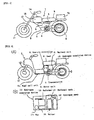
- Fig. 1 is a general structural view of a hybrid-driven vehicle according to an embodiment of this invention.
- the hybrid-driven vehicle 1 of this embodiment is applied to a motor bicycle.
- the hybrid-driven vehicle 1 is provided with a hybrid-driven system 2.
- the hybrid-driven system 2 comprises an electric motor unit 3, a transmission 4, a vehicle controller 5, a battery unit 6 and a fuel cell unit 7.
- a fuel cell sub-unit 7a comprised mainly of a fuel cell and a reformer, is disposed rearwardly of a seat 8 and upwardly of a drive wheel 9.
- a methanol tank 13 In front of the seat 8 and between the seat and a front fork 12 for steering a steering wheel 11, is disposed a methanol tank 13.
- the methanol tank 13 is provided with a filler cap 14.
- the hybrid system comprised of a fuel cell in the fuel cell sub-unit 7a and a battery in the battery unit 6 is adapted to drive an electric motor in the electric motor unit 3 to rotate the drive wheel 9.
- the fuel cell sub-unit comprised mainly of a fuel cell body and the reformer may be disposed at a position shown by numeral 13, and the methanol tank, at a position shown by numeral 7.
- Fig. 2(A) is a view of an example of another type of hybrid-driven motor bicycle
- Fig. 2(B) is a structural view of a hydrogen supplying device for the fuel cell.
- the hybrid-driven vehicle 1 has a vehicle controller 5 and a battery unit 6 under a seat 8; under a vehicle controller 5 is provided an electric motor unit 3; and in front thereof is provided a fuel cell sub-unit 7b comprised mainly of a fuel cell. On a carrier to the rear of the seat 8 is provided a hydrogen supplying device 15 for supplying hydrogen for power generation to the fuel cell sub-unit 7b.
- the hydrogen supplying device 15 as shown in Fig. 2(B), is provided with a hydrogen bombe 16 together with a methanol tank 13, and with a fan 17 and a burner 18 for supplying combustion air, and further with a reformer 19 for producing hydrogen through catalyst, with primary fuel being heated and vaporized.
- Fig. 3 is a schematic block diagram to the whole of the power transmission system and the control system mounted on the hybrid-driven vehicle according to this invention.
- the hybrid-driven vehicle 1 is provided with a main switch SW1, a seat 8, a stand 20, a foot rest 21, an acceleration grip 22, a brake 23, an indicator 24, a lamp unit 25 including a light, a winker, etc, a user input device 26, a non-volatile memory 27 and a timer 28, and further with an electric motor unit 3, a transmission 4, a vehicle controller 5, a battery unit 6 and a fuel cell unit 7.
- ON/OFF signals are sent from the main switch SW1 to the vehicle controller 5 to drive the motor-powered vehicle.
- To the seat 8, stand 20, foot rest 21 and brake 23 are fitted sensors S1-S4, respectively, and ON/OFF signals are sent from these sensors S1-S4 to the vehicle controller 5, where the respective operating conditions are detected.
- the accelerator grip 22 constitutes output setting means, and to the accelerator grip 22 is fitted an accelerator opening sensor S5, from which signals of accelerator opening are sent to the vehicle controller 5 through gripping manipulation of the driver.
- the electric motor is controlled according to accelerator opening.
- the vehicle controller 5 constitutes control means for controlling the output of the electric motor based on the output setting value from the output setting means constituted by the accelerator grip 22.
- the driver is able to input various data from a user input device 26 to the vehicle controller 5 to change, for example, the operating characteristics of the vehicle. Also, data are transferred between the non-volatile memory 27 and timer 28 and the vehicle controller 5, that is, to the non-volatile memory 27 is stored the information of the operating conditions of the vehicle at the time of stoppage, and the vehicle controller 5 reads the information of the stored operating conditions for control when operation is started.
- the indicator 24 is driven by indicator-ON/OFF signals from the vehicle controller 5 and the operating conditions of the motor-powered vehicle are indicated on the indicator 24.
- the lamp unit 25 including a light, winker, etc is comprised of lamps 25b of the light, winker, etc.
- Activation-ON/OFF signals from the vehicle controller 5 drive a DC/DC converter 25a to light the lamps 25b.
- the electric motor unit 3 is provided with a motor driver 30, an electric motor 31 connected to the drive wheel 9, an encoder 32, a regenerative current sensor S11 and regenerative energy control means 33.
- the motor driver 30 controls the electric motor 31 through duty signals from the vehicle controller 5, and the drive wheel 9 is driven by the output of the electric motor 31.
- the encoder 32 detects the position of the magnetic poles and the number of revolution of the electric motor 31. Information of the motor speed from the encoder 32 is stored in a memory in the motor driver 30 to be sent to the vehicle controller 5 as required. Output of the electric motor 31 is changed in its speed by the transmission 4 to drive the drive wheel 9, and the transmission 4 is controlled by speed-change command signals from the vehicle controller 5.
- the electric motor 31 is provided with a motor voltage sensor or a motor current sensor S7, and information of the voltages and currents of the motor is stored in a memory in the motor driver to be sent to the vehicle controller 5 as required.
- the battery unit 6 is provided with a battery 60, a battery controller 61 and a battery relay 62.
- the fuel cell unit 7 is provided with a fuel cell 70 constituting power generating means, a fuel cell controller 71, a reverse current prevention element 72 and a fuel cell relay 73.
- a first power supply path L1 allowing supply of the output current from the fuel cell 70 to the battery 60
- a second power supply path L2 allowing supply of the output current from the battery 60 to the electric motor 31, and electric power is supplied through an electric power regulating section 80.
- the battery controller 61 is provided with detection means for detecting the charging state of the battery 60, and the detection means is comprised of a battery temperature sensor S12, a battery voltage sensor S13 and a battery current sensor S14, and information from these sensors is stored in a memory in the battery controller 61 to be entered in the vehicle controller 5 as required.
- the battery relay 62 is activated by ON/OFF signals from the vehicle controller 5 to control electric power supply from the second power supply path L2.
- Communication data are sent from the vehicle controller 5 to the fuel cell controller 71, and the fuel cell controller 71 controls the fuel cell 70 on the basis of these data.
- the fuel cell controller 71 is provided with detection means for detecting the state of the fuel cell 70.
- the detection means is comprised of various temperature sensors S21, a fuel cell voltage sensor S22 and a fuel cell current sensor S23, and information from these sensors is stored in a memory in the fuel cell controller 71 to be entered in the vehicle controller 5 as required.
- the fuel cell relay 73 connected to the fuel cell controller through rectifier diode (reverse current prevention element) 72 is activated by ON/OFF signals from the vehicle controller 5 to control electric power supply from the first power supply path L1.
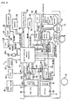
- Fig. 4 is a structural diagram of a portion of a fuel cell according to an embodiment of this invention.
- the fuel cell unit 7 in this embodiment comprises a methanol tank 102, a reformer 103, a shift converter 104, a selective oxidation reactor 105, a fuel cell 70, a moisture collecting heat exchanger 107, a water tank 108 and a fuel cell battery controller 71, various devices such as valves, pumps and fans, and sensors.
- the fuel cell controller 71 is connected to the devices such as valves, pumps and fans, and sensors.
- the reformer 103, shift converter 104, selective oxidation reactor 105 and fuel cell 70 are provided with temperature sensors Tr, Tb, Ts, Tp, Tc, and the temperature of these components is controlled properly by the fuel cell battery controller 71 (Fig. 3) through temperature detection.
- the reformer 103 is provided with a burner 110, an evaporator 111 and a catalyst layer 112.
- To the burner 110 is supplied methanol from the methanol tank 102 by a burner pump 113 activated through temperature detection by the temperature sensor Tb, and air by a burner fan 114, and the evaporator 111 is heated by combustion action of the mixture.
- the double circle in the figure represents an air inlet.
- To the evaporator 111 is supplied methanol fed from the methanol tank 102 by the methanol pump 115, and water fed from the water tank 108 by the water pump 116, with methanol and water mixed together.
- the burner 110 heats the evaporator 111 to vaporize the fuel mixture of methanol and water, and the vaporized fuel mixture in the evaporator 111 is supplied to the catalyst layer 112.
- the burner 110 To the burner 110 is supplied surplus (or bypassing) hydrogen from the fuel cell 70 through a line 201 for combustion.
- the combustion heat of the burner 110 vaporizes primary fuel (raw material) composed of methanol and water, and heats the catalyst layer 112 to maintain its temperature at a value required for catalytic reaction. Combustion gas, and air not involved in the reaction are discharged to the outside through an exhaust passage 202.
- the catalyst layer 112 is made, for example, of Cu-base catalyst, and resolves the mixture of methanol and water into hydrogen and carbon dioxide at a catalyst reaction temperature of about 300 °C as follows: CH 3 OH + H 2 O ⁇ 3H 2 + CO 2
- carbon monoxide in the resolved gas is turned to CO2 at a reaction temperature of about 200 °C in the following chemical reaction by surplus water vapor: CO + H 2 O ⁇ H 2 + CO 2 and CO concentration is lowered to the order of about 0.1%.
- CO is further changed chemically to CO2 at a catalyst temperature of about 120 °C using platinum-base catalyst in the oxidation reaction as: 2CO + O 2 ⁇ 2CO 2 and its concentration is reduced further to 1/10 of the previous value or smaller.
- the CO concentration in the cell 70 can be lowered to the order of some tens of ppm.
- the reformer 103 allows raw material to be reformed so as to produce hydrogen as described above, and the hydrogen acquired is supplied to the fuel cell 70 through the shift converter 104 and the selective oxidation reactor 105. Between the reformer 103 and the shift converter 104 are provided a buffer tank 117 for absorbing pulsation and pressure change and switching valves 117a, 117b, and the hydrogen is returned to the burner 110 through activation of these switching valves 117a, 117b.
- the shift converter 104 is cooled by a cooling fan 118 after temperature detection by the temperature sensor Ts. Cooling air is discharged to the outside through an exhaust passage 203.
- a buffer tank 124 and switching valves 124a, 124b are provided between the shift converter 104 and the selective oxidation reactor 105.
- Hydrogen sent from the shift converter 104 is mixed with air fed by a reaction air pump 119 to be supplied to the selective oxidation reactor 105.
- the selective oxidation reactor 105 is cooled by a cooling fan 120 after temperature detection by the temperature sensor Tp.
- the cooling air is discharged to the outside through an exhaust passage 204.
- a buffer tank 121 and switching valves 121a, 121b are provided between the selective oxidation reactor 105 and the fuel cell 70.
- hydrogen is returned to the burner 110 in the reformer 103 through activation of these switching valves.
- the amount of hydrogen supplied to the fuel cell 70 can be regulated for output control. Excessive oxygen is supplied in this case, so that output is controlled according to the amount of hydrogen.
- Such an output control is performed as follows: required output is calculated by the vehicle controller 5 based on the data from sensors S21-S23 and the detected data of the operating conditions from other various sensors, the flow rate of each switching valve is calculated by the vehicle controller 5 or the fuel cell controller 71 based on the calculation results, taking account of the time lag required for the hydrogen quantity in the cell to be changed after activation of the switching valve, on the basis of which ON/OFF control or opening control of each switching valve is performed by the fuel cell controller 71.
- a larger supply quantity of the primary fuel such as methanol may increase the amount of evaporation of hydrogen to thereby increase output, in which case time lag is produced by the time hydrogen is increased in quantity enough to participate in power generation.
- time lag is compensated for by the electric power from the battery.
- To the fuel cell 70 is supplied water from the water tank 108 by a cooling and humidifying pump 122, and air is supplied from the moisture collection heat exchanger 107 by a pressurizing air pump 123 through temperature detection of the temperature sensor Tc. Using the water, air and hydrogen, power generation is performed in the fuel cell 70, as described below.
- the fuel cell 70 is configured such that electrodes are each formed with, for example, a platinum-base porous catalyst layer (not shown) provided on both sides of a cell film (not shown) with a cooling and humidifying water passage 205 formed therein.
- a platinum-base porous catalyst layer (not shown) provided on both sides of a cell film (not shown) with a cooling and humidifying water passage 205 formed therein.
- oxygen (air) supplied to one electrode is supplied hydrogen from the selective oxidation reactor 105 through a hydrogen passage 206, and to the other electrode, oxygen (air) through an oxygen passage 207.
- Hydrogen ions move from the hydrogen passage 205 of the hydrogen side electrode to the oxygen side electrode through the cell film and are combined with oxygen to form water.
- the migration of electrons (-) associated with the migration of the hydrogen ions (+) allows an electric current to flow between the electrodes for power generation.
- This power generating reactor is a heat development reactor, and for the purpose of cooling and smooth migration of hydrogen ions to the oxygen side electrode, water is supplied from the water tank 108 to the water passage 205 in the cell film between both electrodes by the pump 122.
- the water tank 108 is provided with a radiation fins 208 for cooling water.
- Numeral 20 designates an overflow pipe.
- Air is introduced to the heat exchanger 107.
- the air after exchanging heat with water at an elevated temperature, is turned to a hot air, and supplied to the oxygen passage 207 by the air pump 123.
- an air inlet shown in the figure by a double circle
- Oxygen in the air passing through the oxygen passage 207 and combined with hydrogen ions is turned into water and collected in the water tank 108.
- the surplus air (oxygen and nitrogen) is discharged to the outside through an exhaust passage 210.
- the reformer 103 in which the evaporator 111 is heated by the burner 110 and raw material vaporized by the evaporator 111 is supplied to the catalyst layer 112, the raw material is reformed to produce hydrogen, and the hydrogen acquired is supplied to the fuel cell 70 through the shift converter 104 and the selective oxidation reactor 105 for power generation.
- hydrogen acquired from the selective oxygen reactor 105 may be stored, as shown in Fig. 2(B), temporarily in the hydrogen bombe 16.
- the output of the fuel cell 70 is connected to the power regulating section 80 through the reverse current prevention element 72 and the fuel cell battery relay 73, and the power regulating section 80 is connected to the battery 60 and the electric motor 31.
- a reformer 103, a shift converter 104, a selective oxidation reactor 105, etc are used for producing hydrogen gas with methanol as a row material
- any one of gasoline, methane and butane may be held in a tank and a reformer 103 carrying catalyst corresponding to the raw material, a shift converter 104, a selective oxidation reactor 105, etc, may be used to produce hydrogen gas for the fuel cell 70.
- a fuel cell unit 7 may be comprised mainly of a fuel cell and a hydrogen gas bombe containing a hydrogen-gas storing alloy, and this hydrogen bombe may be mounted exchangeably on the fuel cell unit 7. In this case, the hydrogen bombe is filled with hydrogen gas of high purity produced for industrial use in a factory.
- Fig. 5 is a block diagram of the power source control system of the hybrid-driven vehicle according to this invention.
- the vehicle controller 5 is connected to the electric motor unit 3, battery unit 6 and fuel cell unit 7 through two-way communication lines 220, 221, 222, respectively.
- the fuel cell unit 7 is connected to the electric motor unit 3 through (+) side current line 223a and (-) side current line 223b.
- a switch 225 On the (+) side current line 223a is provided a switch 225. This switch 225 is turned ON and OFF by the vehicle controller 5.
- the battery unit 6 is connected to the electric motor unit 3 through the (+) side current line 223a and the (-) side current line 223b which are directly connected to the (+) side current line 224a and (-) side current line 224b, respectively.
- a switch 226 On the (+) side current line 224a is provided a switch 226. This switch 226 is turned ON and OFF by the vehicle controller 5.
- the electric motor unit 3 is a unit in which a motor driver 30, an encoder and sensors, as well as an electric motor 31 (Fig. 3), are integrated together as a module.
- Such an electric motor unit 3 can be mounted detachably on a vehicle as a unitary component. Therefore, the two-way communication line 220 and the current lines 223a, 223b, 224a, 224b are each adapted to connect the electric motor unit 3 and the vehicle controller through the respective couplers (not shown).
- Detected data such as the operating conditions of the electric motor unit 3 (for example, number of revolution), throttle opening, running speed, request load, temperature and shift position are sent to the vehicle controller 5 to update the memory in the vehicle controller 5 for storage.
- the battery unit 6 is a unit in which a battery controller 61, sensors S12-S14 and a relay 52, as well as a battery 60 as shown in Fig. 3, are integrated together as a module.
- a battery unit 6 can be mounted detachably on a vehicle as a unitary component. Therefore, the two-way communication line 221 and the current lines 224a, 224b are connected to the battery controller 61 of the battery unit 6 through couplers (not shown).
- the battery controller 61 has a memory, to which are stored the data of the battery unit conditions such as temperature, voltage and current, and the remaining capacity of the battery 60 while updated constantly.
- the data can be transferred through two-way communication between the battery controller and the vehicle controller to supply required power during running, and when the battery 60 is replaced, the remaining capacity can be immediately recognized by the vehicle controller for processing of expected travel distance, etc.
- the fuel cell unit 7 is a unit in which a fuel cell controller 71, sensors S21-S23 (Fig. 3) and a relay 52, as well as the fuel cell 70, reformer, etc, are integrated together as a module.
- a fuel cell unit 7 can be mounted detachably on a vehicle as a unitary component. Therefore, the two-way communication line 222 and the current lines 223a, 223b are connected to the fuel cell controller 71 of the fuel cell unit 7 through couplers (not shown).
- the fuel cell controller 71 has a memory, to which are stored the data of the fuel cell unit conditions such as temperature, voltage and current, and the capacity (specifically, the remainder in the methanol tank) of the fuel cell while updated constantly.
- the data can be transferred through two-way communication between the fuel cell controller and the vehicle controller to supply required power during running, and processing of expected travel distance, etc can be performed.
- a fuel cell and a battery are used for two power supply sources constituting the hybrid-driven vehicle, two fuel cells or two batteries (second batteries) may be used, or an engine type generator or a capacitor may be used.
- this invention can be applied to watercrafts or other equipment in addition to vehicles.
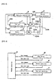
- Fig. 6 is an illustration of data communication in the control system of the hybrid-driven vehicle according to this invention.
- the vehicle controller 5 transmits, to the electric motor unit 3 (encoder 32 and other sensor group), battery controller 61 and fuel cell controller 71, request signals of various data stored in the memories of the controllers. Upon this data request, required data are sent back to the vehicle controller 5 from the sensor group of the electric motor unit 3, and the controllers 61, 71.
- the contents of the data include the state information such as temperature, voltage, current, error information and capacity, and the control information such as output request.
- the vehicle controller 5 calculates, on the basis of the data from the sensor group and the controllers 61, 71, the optimum amount of drive to the units, and the data of the amount of drive are sent, as operation command data, to the motor driver 30 and controllers 61, 71 for the control of the electric motor unit 3, battery unit 6 and fuel cell unit 7.
- Fig. 7 and Fig. 8 are flowcharts of the control carried out by the vehicle controller 5.
- Fig. 9 is a flowchart of the operation control of the fuel cell.
- Fig.10 is a graph, illustrating burden ratios of a power source in a power source control method for a motor-powered vehicle according to an embodiment of the invention.
- the drawing shows patterns of the load change for an electric motor of an motor-powered bicycle.
- the term "load” is referred as the requested load inputted through a accelerator grip by a driver (for example, intention to accelerate speed or to maintain speed at an ascending slope, i.e. a request to the output of the electric motor from an driver) or referred as the external load applied on an electric motor from the external, such as air resistance and ascending or descending slope.
- the load described herein shall be the output to be provided by the electric motor. This output to be provided should be balanced with the external load and increased or decreased in response to the external load.
- a lightweight vehicle such as a two-wheeled vehicle
- external load is apt to change due to irregular road surfaces
- the speed is also apt to vary corresponding to the output change, due to its lightweight
- the requested load is further apt to change when the driver intends to enjoy his driving.
- symbol “a” denotes the whole load change and symbol “b” denotes part of the whole change, the load level of which is lower than that of the part "c" of the whole change, that is, symbol “b” denotes the load in the part substantially having no change of load (i.e. "base load” referred in this invention).
- the electric power corresponding to the base load “b” is supplied from the fuel cell and the electric power corresponding to the load of change part "c" exceeding the base load is supplied from the battery.
- the load change “c” varies finely with time progress, but the base load is maintained at approximately constant value and the resultant change pattern is gradual.
- the base load “b” as the targeted value for the output of the fuel cell is determined depending on the load level. For example, it is determined as the given ratio to the average value of the changed loads. Also, the rate of the base load may be determined corresponding to operation modes or the like.
- the fuel cell having inactive response can follow the load change slowly during long time period and the battery ensures to follow the fine change part only, thereby to achieve a driving control in which superior characteristics of both power sources is fully put to practical use and to improve their responsiveness to the load.
- the burden on the battery is reduced, resulting in no abrupt application of load as well as no abrupt reduction of capacity. This causes no shortage of capacity during running and therefore the number of miles driven is secured. Furthermore, long life span is achieved as the deterioration is suppressed.
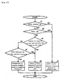
- Fig.11 is a flow chart for the power source control method according to the invention and Fig.12 is a graph, showing the change of battery capacity in Fig.11.
- the battery capacity For the battery capacity, if the electrical charge is incommensurate, the output becomes short and therefore the number of miles driven is not ensured with deterioration of the battery being accelerated. On the contrary, if the electrical charge is excessive, the battery is deteriorated due to overcharge or overcurrent caused by regenerative current. Accordingly, it is desired to maintain the battery capacity at the adequate level.
- the battery capacity is detected (Step c1).
- the detected battery capacity is discriminated whether larger or smaller than the lower limit of warning (Step c2).
- This lower limit of warning may be, for example, 50% of the maximum capacity. If the battery capacity is not more than the lower limit (50%) of warning (at the point B in Fig.12), then the instruction to increase the output of the fuel cell is sent (Step c3). In this step, the warning may be displayed though LED or the like.
- the increase of the output of the fuel cell causes the reduction of the burden loaded on the battery and therefore part of the increase of the output of the fuel cell charges the battery to increase the battery capacity.
- Step c3 if the battery capacity is not less than the lower limit of warning, then at Step c4 the battery capacity is discriminated whether larger or smaller than the upper limit of warning.
- This upper limit of warning may be, for example, 70% of the maximum capacity. If the battery capacity is not less than the upper limit of warning (at the point A in Fig.12), then the instruction for decreasing the output of the fuel cell is sent (Step c5). Also, in this step, the warning may be displayed though LED or the like. The decrease of the output of the fuel cell causes the increase of the burden loaded on the battery and therefore the battery discharge increases, resulting in the reduction of battery capacity.
- the battery capacity can be always maintained between the upper usage limit (for example 80%) and the lower usage limit (for example 40%) by comparing the battery charge with the upper limit (70%) of warning and the lower limit (50%) of warning and then controlling. As a result, the deterioration of battery is suppressed.
- Fig. 13 is a graph, showing the change of battery capacity in the power source control method of the invention.
- the output of the fuel cell is reduced.
- the discharge from the battery increases and at the time T2 the capacity is reduced to the upper limit, where in turn the output of the fuel cell is increased again to return to the original value.
- normal driving is continued and then at the time T3 if the battery capacity is reduced under the lower limit, then the output of the battery is increased. This causes the discharge from the battery to stop and then the charging is performed.
- the battery capacity achieves the predetermined level, the output of the fuel cell is returned to the original value and then the hybrid driving with the battery is performed according to the normal control program for driving.
- Fig.14 is a graph, showing patterns of load change according to another embodiment of the invention.
- This embodiment is an example in which this invention is applied to a power-assisted bicycle having an electric motor
- the power-assisted bicycle is one in which human power (out put) acting upon the pedals can be transmitted to a wheel by a power transmission such as a chain, the output of an electric motor is combined with the human power at any portion of the power transmission and the resulting force can be also transmitted to a wheel.
- the output of the electric motor shall be obtained by multiplying the pedaling force acting on pedals by a given positive coefficient. Therefore, the output (equal to the load) to be provided by the electric motor is correlated with the pedaling force.
- the maximum pedaling force is limited by the driver's weight and the bottom value (minimum pedaling force) in each wave of varied pedaling force is approximately zero. Therefore, patterns of load change are shown in Fig.14.
- the fuel cell charges a constant base load "b" and the battery charges the changed part "c" exceeding the load "b.”
- the base load "b” is preset in each driving mode, based on the output of the known average load level of a normal motor-assisted bicycle. As the vehicle controller of this motor-assisted bicycle has learning function, the base load "b” may be set by calculating the average load level from the latest running data for every running mode according to effected by turning on the main switch, and correcting the base load "b" for every running.
- the fuel cell When the vehicle is stopped for a short period due to, for example the waiting for traffic signals (time T in the drawing), the fuel cell continues to generate power without shut down fuel cell and as a result the battery is charged. Provided that the battery capacity is not more than the given upper limit. In such a manner that the fuel cell does operate during a short time stoppage of the bicycle, the warm-up time for restart is not required and stable output from the fuel cell can be obtained.
- the base load shall be an envelope curve (maximum load line) formed of a line connecting peaks of varied waves, the battery is always charged.
- the base load shall be an median line between the maximum load line and a line connecting valleys of load waves, the battery charge is balanced with the battery discharge. It is desirable to make the base load constant as far as possible. Even if it cannot be made constant, it should be set such that the absolute of the differential value is smaller than that of changed load:
- the base load is set at least such that the wave has frequency higher than that changed load waves.
- the fuel cell having responsiveness lower than that of the battery can also follow to generate.
- the battery In the area where the changed load waves is larger than the base load "a,” the battery is discharged and the area where it is smaller, it is charged.
- the base load "b" may be set larger than the median line if the capacity is less than the given value or further may be larger than the maximum load line.
- the base load "b" may be set smaller than the median line if the capacity is more than the given value or further may be smaller than the minimum load line.
- Fig. 15 is a flow chart, showing a subroutine of generation control for determining a temporary stoppage and charging the battery.
- the main stand switch (sensor 2) of the stand 20 (Fig.3) is determined whether it is in ON or OFF. If the stand is in use (ON), it is determined as the vehicle being in stoppage and the amount of generation is calculated according the stand by mode for next driving (Step d7). If the stand is not used (OFF), the seat switch (sensor 1) on the seat 8 is determined whether it is in ON or OFF (Step d2). If it is not seated (OFF), it is determined as the vehicle being in stoppage and the amount of generation is calculated according the stand by mode for next driving (Step d7).
- Step d3 it is determined whether or not the right and left feet are on the right and left footrests for more than specified time period. This is decided depending on the ON/OFF state of the right and left footrests. If both feet are on the footrest for more than specified time period, the vehicle is determined to be in stoppage, the amount of generation is calculated according to the normal running generation mode (Step d6).
- Step d3 If seated and the feet rest on the footrests ("NO" at Step d3), it is determined with the signal from an encoder, whether the speed of the motor 31 is zero (or not more than the specified speed) for more than specified time period (Step d4). If the speed is not less than the specified speed, it is determined that the vehicle is running (the vehicle is driven with the driver's foot is away from the footrests for the meantime and then the amount of generation is calculated according to the normal running generation mode (Step d6).
- Step d4 if the motor speed is zero (or not more than the specified speed) for the specified time period, it is determined as the temporary stoppage and then the amount of generation is calculated according to the temporary stoppage generation mode (Step d5).
- Fig.16 is a graph, showing the change of the battery capacity during temporary stoppage.
- the temporary stoppage of the vehicle is detected and then the charge is initiated.
- the battery capacity is gradually increased, and at T6, the vehicle is started. After the start, the battery capacity is gradually reduced. Additionally, against the acute increase of the load at start, the output of the fuel cell is also increased.
- Fig. 17 is a flow chart of another embodiment of the invention.
- This embodiment is a power source control method for controlling the output of the fuel cell, on the basis of the calculated average of the output current from means for storing the last running state.
- the fuel cell constantly bears a load of a given level as a base load portion
- the secondary battery bears a varying load portion exceeding the base load portion. Therefore, electric power is supplied from the fuel cell with constant stability for the base load portion which is constant with respect to time or varies slowly according to the operating mode, while electric power is supplied from the battery for the finely varying load portion exceeding the base load portion, thereby decreasing burden of the battery, preventing abrupt capacity drop or deterioration of the battery, and ensuring stable running by sharing the whole load efficiently between the fuel cell and the battery.
Landscapes
- Engineering & Computer Science (AREA)
- Life Sciences & Earth Sciences (AREA)
- Sustainable Development (AREA)
- Sustainable Energy (AREA)
- Power Engineering (AREA)
- Transportation (AREA)
- Mechanical Engineering (AREA)
- Electric Propulsion And Braking For Vehicles (AREA)
- Fuel Cell (AREA)
Applications Claiming Priority (2)
| Application Number | Priority Date | Filing Date | Title |
|---|---|---|---|
| JP26731999 | 1999-09-21 | ||
| JP26731999A JP2001095107A (ja) | 1999-09-21 | 1999-09-21 | ハイブリッド駆動式移動体の電源制御方法 |
Publications (2)
| Publication Number | Publication Date |
|---|---|
| EP1086847A2 true EP1086847A2 (de) | 2001-03-28 |
| EP1086847A3 EP1086847A3 (de) | 2002-04-03 |
Family
ID=17443178
Family Applications (1)
| Application Number | Title | Priority Date | Filing Date |
|---|---|---|---|
| EP00120677A Withdrawn EP1086847A3 (de) | 1999-09-21 | 2000-09-21 | Regelungsverfahren für die Stromversorgung eines hybrid-getriebenen bewegten Geräts |
Country Status (4)
| Country | Link |
|---|---|
| US (1) | US6555928B1 (de) |
| EP (1) | EP1086847A3 (de) |
| JP (1) | JP2001095107A (de) |
| CA (1) | CA2320433A1 (de) |
Cited By (13)
| Publication number | Priority date | Publication date | Assignee | Title |
|---|---|---|---|---|
| WO2002036385A1 (en) * | 2000-10-31 | 2002-05-10 | Nissan Motor Co., Ltd. | Operating load control for fuel cell power system in fuel cell vehicle |
| EP1275553A2 (de) | 2001-06-15 | 2003-01-15 | Toyota Jidosha Kabushiki Kaisha | Stromversorgungsvorrichtung mit einer Brennstoffzelle und Verfahren dafür |
| WO2003069718A1 (de) * | 2002-02-12 | 2003-08-21 | Heliocentris Energiesysteme Gmbh | Herausnehmbare brennstoffzellenanlage zur energieversorgung einer mobilen maschine |
| WO2003099633A1 (de) * | 2002-05-28 | 2003-12-04 | Volkswagen Ag | Dynamischer, sicherheitsrelevanter hochstromverbraucher in einem kraftfahrzeugbordnetz |
| EP1375239A2 (de) | 2002-06-24 | 2004-01-02 | Delphi Technologies, Inc. | Verfahren und Vorrichtung zum Steuern eines Brennstoffzellensystems |
| FR2901071A1 (fr) * | 2006-05-09 | 2007-11-16 | Renault Sas | Systeme et procede de production d'energie electrique pour vehicule automobile a moteur de traction electrique |
| EP1706930A4 (de) * | 2004-01-22 | 2008-03-12 | Jadoo Power Systems Inc | Brennstoffzelle-leistungs- und -verwaltungssystem und steuer- und betriebssystem dafür |
| EP1967407A1 (de) * | 2007-03-06 | 2008-09-10 | The Boeing Company | Hybride elektrische Stromquelle |
| GB2452308A (en) * | 2007-08-31 | 2009-03-04 | Antig Technology Corp | Electric power system with hybrid energy sources |
| WO2011008377A1 (en) * | 2009-07-13 | 2011-01-20 | Illinois Tool Works Inc. | Hybrid welding systems and devices comprising a fuel cell and an energy storage device |
| EP2361827A3 (de) * | 2010-02-19 | 2013-03-27 | Yamaha Hatsudoki Kabushiki Kaisha | Elektromotorrad |
| WO2018202348A1 (de) * | 2017-05-04 | 2018-11-08 | Robert Bosch Gmbh | Verfahren und system zum betrieb eines brennstoffzellensystems |
| EP4420921A1 (de) * | 2023-02-21 | 2024-08-28 | Volvo Truck Corporation | Computerimplementiertes verfahren zur steuerung eines stromversorgungssystems eines fahrzeugs |
Families Citing this family (73)
| Publication number | Priority date | Publication date | Assignee | Title |
|---|---|---|---|---|
| JP4596657B2 (ja) * | 2001-02-01 | 2010-12-08 | 株式会社Ihi | 燃料電池システム |
| JP2002289238A (ja) * | 2001-03-26 | 2002-10-04 | Denso Corp | 燃料電池システム |
| JP3745309B2 (ja) | 2001-06-12 | 2006-02-15 | 本田技研工業株式会社 | 燃料電池自動車の制御装置 |
| JP2003243010A (ja) * | 2002-02-13 | 2003-08-29 | Nissan Motor Co Ltd | 燃料電池車両 |
| US6752229B2 (en) * | 2002-07-23 | 2004-06-22 | Chien-Chang Ho | Vehicle with motor and engine |
| DE10233821A1 (de) | 2002-07-25 | 2004-02-05 | Daimlerchrysler Ag | Verfahren und Anordnung zur Steuerung der Energieversorgung einer wenigstens einen elektrischen Antriebsmotor aufweisenden, mobilen Vorrichtung mit einem hybriden Energiesystem, das ein Brennstoffzellensystem und ein dynamisches Energiesystem enthält |
| US20040044448A1 (en) * | 2002-08-27 | 2004-03-04 | Ford Motor Company | Vehicle systems controller with modular architecture |
| US6792341B2 (en) * | 2002-10-23 | 2004-09-14 | Ford Motor Company | Method and system for controlling power distribution in a hybrid fuel cell vehicle |
| US6732942B1 (en) * | 2002-11-19 | 2004-05-11 | Delphi Technologies, Inc. | Heating, venting, and air conditioning system for providing supplemental heat in a vehicle |
| US20040166746A1 (en) * | 2003-02-25 | 2004-08-26 | Krietzman Mark H. | Electric personal water craft |
| JP3793168B2 (ja) * | 2003-04-01 | 2006-07-05 | 株式会社シマノ | 自転車用電源装置及び自転車用電力供給方法 |
| US6795756B1 (en) * | 2003-04-16 | 2004-09-21 | Ford Motor Company | Method and system for controlling power distribution in a hybrid fuel cell vehicle |
| JP3933096B2 (ja) * | 2003-06-03 | 2007-06-20 | トヨタ自動車株式会社 | 車両に搭載されたバッテリ制御装置および制御方法 |
| JP2005032039A (ja) * | 2003-07-07 | 2005-02-03 | Sony Corp | 電子機器及び電子機器の電源管理制御方法、並びに電源装置 |
| DE10330815A1 (de) * | 2003-07-08 | 2005-01-27 | Still Gmbh | Flurförderzeug mit einem elektrischen Antrieb und einem Brennstoffzellensystem und Verfahren zum Betrieb eines Flurförderzeugs |
| JP2005063748A (ja) * | 2003-08-08 | 2005-03-10 | Hitachi Home & Life Solutions Inc | 燃料電池システム |
| US6846208B1 (en) * | 2003-11-03 | 2005-01-25 | Lockheed Martin Corporation | Wave rotor based power and propulsion generation for a marine vessel |
| JP4188227B2 (ja) * | 2003-12-26 | 2008-11-26 | 本田技研工業株式会社 | 車両 |
| US20050260471A1 (en) * | 2004-05-18 | 2005-11-24 | Logan Victor W | Electrical current measurement in a fuel cell |
| US20070256872A1 (en) * | 2004-08-18 | 2007-11-08 | Shigeki Yamamuro | Electric Wheelchair |
| JP4684598B2 (ja) * | 2004-08-20 | 2011-05-18 | 本田技研工業株式会社 | 燃料電池車両における懸架装置 |
| US20060046107A1 (en) * | 2004-09-01 | 2006-03-02 | Caterpillar Inc. | System for fuel cell power plant load following and power regulation |
| JP5119568B2 (ja) * | 2004-10-06 | 2013-01-16 | 日産自動車株式会社 | 燃料電池システムの制御装置及び燃料電池システムの制御方法 |
| JP2006252954A (ja) * | 2005-03-10 | 2006-09-21 | Fujitsu Ltd | 燃料電池装置、その制御方法及び電子機器 |
| JP2006252953A (ja) * | 2005-03-10 | 2006-09-21 | Fujitsu Ltd | 燃料電池装置及び電子機器 |
| JP5051989B2 (ja) * | 2005-08-04 | 2012-10-17 | トヨタ自動車株式会社 | 電圧制御システム及び移動体 |
| JP2007068358A (ja) * | 2005-09-01 | 2007-03-15 | Toyota Motor Corp | 電動車両 |
| JP2007099059A (ja) * | 2005-10-04 | 2007-04-19 | Yamaha Motor Co Ltd | 水素貯蔵容器搭載自動二輪車 |
| JP2007327625A (ja) * | 2006-06-09 | 2007-12-20 | Yamaha Motor Co Ltd | ガス供給装置およびこれを備えた移動体 |
| US20080180058A1 (en) * | 2007-01-30 | 2008-07-31 | Bijal Patel | Plug-in battery charging booster for electric vehicle |
| JP5109468B2 (ja) * | 2007-05-14 | 2012-12-26 | 富士電機株式会社 | 燃料電池発電システム |
| US8122985B2 (en) * | 2007-07-30 | 2012-02-28 | GM Global Technology Operations LLC | Double-ended inverter drive system for a fuel cell vehicle and related operating method |
| FR2923187B1 (fr) * | 2007-11-05 | 2009-11-13 | Renault Sas | Procede de gestion de l'energie dans un vehicule automobile |
| DE102008045099A1 (de) * | 2008-06-19 | 2009-12-31 | GM Global Technology Operations, Inc., Detroit | Doppelseitiges Wechselrichterantriebssystem für ein Brennstoffzellenfahrzeug und zugehöriges Betriebsverfahren |
| JP5319177B2 (ja) * | 2008-06-19 | 2013-10-16 | 本田技研工業株式会社 | 燃料電池移動体 |
| US8328214B2 (en) * | 2008-07-15 | 2012-12-11 | Tai-Her Yang | Manpower-driven device with bi-directional input and constant directional rotation output |
| US8297636B2 (en) * | 2008-07-15 | 2012-10-30 | Tai-Her Yang | Manpower-driven device with bi-directional input and constant directional rotation output |
| JP2010063265A (ja) * | 2008-09-03 | 2010-03-18 | Toyota Industries Corp | 燃料電池搭載車両 |
| JP5406561B2 (ja) * | 2009-02-27 | 2014-02-05 | ヤマハ発動機株式会社 | 燃料電池システムおよびそれを備える輸送機器 |
| US8486574B2 (en) | 2009-07-14 | 2013-07-16 | Ford Global Technologies, Llc | Method and system for power control in an automotive vehicle |
| JP5101583B2 (ja) | 2009-09-16 | 2012-12-19 | 本田技研工業株式会社 | 燃料電池車両 |
| JP4915447B2 (ja) * | 2009-12-25 | 2012-04-11 | トヨタ自動車株式会社 | バッテリの車両搭載構造 |
| JP5608032B2 (ja) * | 2010-09-30 | 2014-10-15 | 本田技研工業株式会社 | 電動二輪車の車両接近告知装置 |
| CN103201153B (zh) * | 2010-11-04 | 2016-01-20 | 丰田自动车株式会社 | 混合动力车辆的控制装置 |
| WO2012061819A1 (en) * | 2010-11-05 | 2012-05-10 | Aerobic Cruiser Hybrid Cycles, Llc | Electric vehicle power regulating control method with manual-assist hybrid modes |
| JP2012142120A (ja) * | 2010-12-28 | 2012-07-26 | Jx Nippon Oil & Energy Corp | 燃料電池システム |
| JP5356423B2 (ja) * | 2011-01-21 | 2013-12-04 | 日立建機株式会社 | 旋回体を有する建設機械 |
| US20120203404A1 (en) * | 2011-02-04 | 2012-08-09 | GM Global Technology Operations LLC | Method for heating hybrid powertrain components |
| WO2012129809A1 (zh) * | 2011-03-31 | 2012-10-04 | Hung Jui-Tung | 能源管理和能源生产系统 |
| US8919483B2 (en) | 2012-01-03 | 2014-12-30 | Hero Motorcorp, Ltd. | Ridden vehicle with integrated fuel tank |
| US8950539B2 (en) | 2012-01-03 | 2015-02-10 | Hero Motorcorp Ltd. | Lightweight integrated rear suspension and drive enclosure for a ridden motorized vehicle |
| CN104684799B (zh) | 2012-10-02 | 2019-05-07 | 布里福运动公司 | 踏板车组件 |
| JP5948210B2 (ja) * | 2012-10-15 | 2016-07-06 | 株式会社豊田自動織機 | 車両に搭載される燃料電池システム |
| US8996261B2 (en) | 2012-10-25 | 2015-03-31 | Toyota Motor Engineering & Manufacturing North America, Inc. | Automobile paddle shifters locking device and system |
| US8996260B2 (en) | 2012-10-25 | 2015-03-31 | Toyota Motor Engineering & Manufacturing North America, Inc. | Automobile paddle shifters with first and second positions |
| US9002597B2 (en) | 2012-10-26 | 2015-04-07 | Toyota Motor Engineering & Manufacturing North America, Inc. | Automobile paddle shifters with secondary paddles |
| JP6057209B2 (ja) * | 2012-11-15 | 2017-01-11 | パナソニックIpマネジメント株式会社 | 発電システムおよび発電システムの運転方法 |
| USD712980S1 (en) | 2013-05-17 | 2014-09-09 | Bravo Sports | Scooter connector tubing |
| US10189533B2 (en) | 2013-12-18 | 2019-01-29 | Bravo Sports | Electric scooter |
| US9592876B2 (en) | 2013-12-18 | 2017-03-14 | Bravo Sports | Three-wheeled electric scooter |
| CA2996844A1 (en) * | 2014-08-29 | 2016-06-16 | Tzunum, Inc. | Power train for a hybrid-electric aircraft |
| JP6225218B2 (ja) * | 2016-05-23 | 2017-11-01 | 公益財団法人鉄道総合技術研究所 | 燃料電池鉄道車両の電力制御方法 |
| EP3340355B1 (de) * | 2016-12-20 | 2020-02-05 | The Boeing Company | Hybrides leistungssystem und steuerverfahren dafür |
| JP6546612B2 (ja) * | 2017-02-21 | 2019-07-17 | 株式会社Subaru | 電池システムの制御装置及び電池システム |
| JP7251913B2 (ja) | 2017-06-28 | 2023-04-04 | トヨタ自動車株式会社 | 機械の設計方法 |
| US10486767B1 (en) * | 2019-08-23 | 2019-11-26 | Civilized Cycles Incorporated | Electric bicycle with integrated air supply system |
| DE102020204739A1 (de) * | 2020-04-15 | 2021-10-21 | Robert Bosch Gesellschaft mit beschränkter Haftung | Steuergerätearchitektur |
| JP7579078B2 (ja) * | 2020-07-31 | 2024-11-07 | 川崎重工業株式会社 | 舶用電源システム |
| DE102020213771A1 (de) * | 2020-11-02 | 2022-05-05 | Robert Bosch Gesellschaft mit beschränkter Haftung | Verfahren zum Überwachen einer Energiequelle in einem Bordnetz |
| JP7564072B2 (ja) * | 2021-10-06 | 2024-10-08 | 株式会社豊田自動織機 | 燃料電池システム |
| US20230271513A1 (en) * | 2022-02-21 | 2023-08-31 | Ford Global Technologies, Llc | Method and System for Coordinating Operation of Fuel Cell System and Traction Battery to Improve Durability and Fuel Economy |
| JP7639794B2 (ja) * | 2022-08-23 | 2025-03-05 | トヨタ自動車株式会社 | 制御装置、プログラム及び制御装置の動作方法 |
| TWI861960B (zh) * | 2023-06-26 | 2024-11-11 | 三陽工業股份有限公司 | 電動車輛之自動關機方法 |
Family Cites Families (5)
| Publication number | Priority date | Publication date | Assignee | Title |
|---|---|---|---|---|
| US4962462A (en) * | 1983-09-29 | 1990-10-09 | Engelhard Corporation | Fuel cell/battery hybrid system |
| JP3687991B2 (ja) * | 1994-02-24 | 2005-08-24 | 株式会社エクォス・リサーチ | ハイブリッド電源装置 |
| GB9410389D0 (en) * | 1994-05-24 | 1994-07-13 | Rover Group | Control of a vehicle powertrain |
| EP0782209A1 (de) * | 1995-12-29 | 1997-07-02 | FINMECCANICA S.p.A. AZIENDA ANSALDO | Versorgungsanordnung mit Brennstoffzellen und Pufferbatterie für energieautonome Fahrzeug mit elektrischem Antrieb |
| ES2167809T5 (es) * | 1996-12-20 | 2013-06-20 | Manuel Dos Santos Da Ponte | Aparato generador híbrido |
-
1999
- 1999-09-21 JP JP26731999A patent/JP2001095107A/ja active Pending
-
2000
- 2000-09-21 US US09/666,778 patent/US6555928B1/en not_active Expired - Fee Related
- 2000-09-21 EP EP00120677A patent/EP1086847A3/de not_active Withdrawn
- 2000-09-21 CA CA002320433A patent/CA2320433A1/en not_active Abandoned
Cited By (30)
| Publication number | Priority date | Publication date | Assignee | Title |
|---|---|---|---|---|
| WO2002036385A1 (en) * | 2000-10-31 | 2002-05-10 | Nissan Motor Co., Ltd. | Operating load control for fuel cell power system in fuel cell vehicle |
| US7059436B2 (en) | 2000-10-31 | 2006-06-13 | Nissan Motor Co., Ltd. | Operating load control for fuel cell power system in fuel cell vehicle |
| EP1275553A2 (de) | 2001-06-15 | 2003-01-15 | Toyota Jidosha Kabushiki Kaisha | Stromversorgungsvorrichtung mit einer Brennstoffzelle und Verfahren dafür |
| EP1275553A3 (de) * | 2001-06-15 | 2003-12-03 | Toyota Jidosha Kabushiki Kaisha | Stromversorgungsvorrichtung mit einer Brennstoffzelle und Verfahren dafür |
| EP2444271A1 (de) * | 2001-06-15 | 2012-04-25 | Toyota Jidosha Kabushiki Kaisha | Stromausgabevorrichtung mit Brennstoffzelle und Verfahren dafür |
| US8017276B2 (en) | 2001-06-15 | 2011-09-13 | Toyota Jidosha Kabushiki Kaisha | Power output device with fuel cell and method therefor |
| US8012637B2 (en) | 2001-06-15 | 2011-09-06 | Toyota Jidosha Kabushiki Kaisha | Power output device with fuel cell and method therefor |
| WO2003069718A1 (de) * | 2002-02-12 | 2003-08-21 | Heliocentris Energiesysteme Gmbh | Herausnehmbare brennstoffzellenanlage zur energieversorgung einer mobilen maschine |
| WO2003099633A1 (de) * | 2002-05-28 | 2003-12-04 | Volkswagen Ag | Dynamischer, sicherheitsrelevanter hochstromverbraucher in einem kraftfahrzeugbordnetz |
| EP1375239A2 (de) | 2002-06-24 | 2004-01-02 | Delphi Technologies, Inc. | Verfahren und Vorrichtung zum Steuern eines Brennstoffzellensystems |
| EP1375239A3 (de) * | 2002-06-24 | 2005-04-13 | Delphi Technologies, Inc. | Verfahren und Vorrichtung zum Steuern eines Brennstoffzellensystems |
| US6989211B2 (en) | 2002-06-24 | 2006-01-24 | Delphi Technologies, Inc. | Method and apparatus for controlling a fuel cell system |
| EP1706930A4 (de) * | 2004-01-22 | 2008-03-12 | Jadoo Power Systems Inc | Brennstoffzelle-leistungs- und -verwaltungssystem und steuer- und betriebssystem dafür |
| US7888906B2 (en) | 2004-01-22 | 2011-02-15 | Jadoo Power Systems, Inc. | Power unit for a fuel cell power and management system |
| US7893651B2 (en) | 2004-01-22 | 2011-02-22 | Jadoo Power Systems, Inc. | System for a fuel cell power and management system |
| US7914945B2 (en) | 2004-01-22 | 2011-03-29 | Jadoo Power Systems, Inc. | Fuel cell power and management system, and technique for controlling and/or operating same |
| FR2901071A1 (fr) * | 2006-05-09 | 2007-11-16 | Renault Sas | Systeme et procede de production d'energie electrique pour vehicule automobile a moteur de traction electrique |
| WO2008109276A3 (en) * | 2007-03-06 | 2008-12-18 | Boeing Co | Hybrid electrical power source |
| EP1967407A1 (de) * | 2007-03-06 | 2008-09-10 | The Boeing Company | Hybride elektrische Stromquelle |
| US8427097B2 (en) | 2007-03-06 | 2013-04-23 | The Boeing Company | Hybrid electrical power source |
| GB2452308A (en) * | 2007-08-31 | 2009-03-04 | Antig Technology Corp | Electric power system with hybrid energy sources |
| WO2011008377A1 (en) * | 2009-07-13 | 2011-01-20 | Illinois Tool Works Inc. | Hybrid welding systems and devices comprising a fuel cell and an energy storage device |
| US8405001B2 (en) | 2009-07-13 | 2013-03-26 | Illinois Tool Works Inc | Hybrid welding systems and devices |
| EP2361827A3 (de) * | 2010-02-19 | 2013-03-27 | Yamaha Hatsudoki Kabushiki Kaisha | Elektromotorrad |
| TWI447035B (zh) * | 2010-02-19 | 2014-08-01 | 山葉發動機股份有限公司 | 電動二輪車 |
| WO2018202348A1 (de) * | 2017-05-04 | 2018-11-08 | Robert Bosch Gmbh | Verfahren und system zum betrieb eines brennstoffzellensystems |
| CN110621534A (zh) * | 2017-05-04 | 2019-12-27 | 罗伯特·博世有限公司 | 用于运行燃料电池系统的方法和系统 |
| US11254237B2 (en) | 2017-05-04 | 2022-02-22 | Robert Bosch Gmbh | Method and system for operating a fuel cell system |
| EP4420921A1 (de) * | 2023-02-21 | 2024-08-28 | Volvo Truck Corporation | Computerimplementiertes verfahren zur steuerung eines stromversorgungssystems eines fahrzeugs |
| US12528388B2 (en) | 2023-02-21 | 2026-01-20 | Volvo Truck Corporation | Computer-implemented method for controlling a power system of a vehicle |
Also Published As
| Publication number | Publication date |
|---|---|
| EP1086847A3 (de) | 2002-04-03 |
| US6555928B1 (en) | 2003-04-29 |
| JP2001095107A (ja) | 2001-04-06 |
| CA2320433A1 (en) | 2001-03-21 |
Similar Documents
| Publication | Publication Date | Title |
|---|---|---|
| EP1086847A2 (de) | Regelungsverfahren für die Stromversorgung eines hybrid-getriebenen bewegten Geräts | |
| CA2347666C (en) | Hybrid-driven device | |
| US20090105895A1 (en) | Fuel Cell Vehicle | |
| JP5335047B2 (ja) | 燃料電池システム | |
| US10974672B2 (en) | Vehicle and method of controlling vehicle | |
| US8795861B2 (en) | Fuel cell system and vehicle equipped with the same | |
| JP3770087B2 (ja) | 移動体用電力管理装置 | |
| JP4713758B2 (ja) | 燃料電池発電システム及びその運転方法 | |
| JP5456721B2 (ja) | 燃料電池システム | |
| US7669676B2 (en) | Hybrid propulsion system and method for its operation | |
| WO2001089015A1 (en) | Supply of electric power using fuel cell and chargeable/dischargeable storage | |
| US7550942B2 (en) | Hybrid power supply system and controller for warm-up mode | |
| JP2002141073A (ja) | 移動体用燃料電池システム | |
| US10008728B2 (en) | Fuel cell system and mobile article | |
| JP2001069614A (ja) | ハイブリッド駆動式移動体 | |
| JP5825839B2 (ja) | 燃料電池車両 | |
| JP2001095110A (ja) | ハイブリッド駆動式移動体の電力供給方法 | |
| JP2001095108A (ja) | ハイブリッド駆動式移動体の運転方法 | |
| JP2002321682A (ja) | ハイブリッド式電動車両の制御システム | |
| KR100998305B1 (ko) | 개질기를 이용하는 연료 전지를 구비한 차량에서 에너지를회수하는 방법 및 장치 | |
| JP2005019033A (ja) | 燃料電池システム | |
| JP4438231B2 (ja) | 燃料電池装置及び燃料電池装置の制御方法 | |
| JP2001069615A (ja) | ハイブリッド駆動装置 | |
| JP2007123169A (ja) | 燃料電池システムおよびその制御方法 | |
| JP2001069612A (ja) | ハイブリッド駆動装置 |
Legal Events
| Date | Code | Title | Description |
|---|---|---|---|
| PUAI | Public reference made under article 153(3) epc to a published international application that has entered the european phase |
Free format text: ORIGINAL CODE: 0009012 |
|
| AK | Designated contracting states |
Kind code of ref document: A2 Designated state(s): AT BE CH CY DE DK ES FI FR GB GR IE IT LI LU MC NL PT SE Kind code of ref document: A2 Designated state(s): DE ES FR GB IT NL |
|
| AX | Request for extension of the european patent |
Free format text: AL;LT;LV;MK;RO;SI |
|
| PUAL | Search report despatched |
Free format text: ORIGINAL CODE: 0009013 |
|
| AK | Designated contracting states |
Kind code of ref document: A3 Designated state(s): AT BE CH CY DE DK ES FI FR GB GR IE IT LI LU MC NL PT SE |
|
| AX | Request for extension of the european patent |
Free format text: AL;LT;LV;MK;RO;SI |
|
| 17P | Request for examination filed |
Effective date: 20020930 |
|
| AKX | Designation fees paid |
Free format text: DE ES FR GB IT NL |
|
| 17Q | First examination report despatched |
Effective date: 20090210 |
|
| STAA | Information on the status of an ep patent application or granted ep patent |
Free format text: STATUS: THE APPLICATION HAS BEEN WITHDRAWN |
|
| 18W | Application withdrawn |
Effective date: 20090205 |