EP1086870A2 - Dispositif du type traction-compression pour une barre d'attelage - Google Patents
Dispositif du type traction-compression pour une barre d'attelage Download PDFInfo
- Publication number
- EP1086870A2 EP1086870A2 EP00250233A EP00250233A EP1086870A2 EP 1086870 A2 EP1086870 A2 EP 1086870A2 EP 00250233 A EP00250233 A EP 00250233A EP 00250233 A EP00250233 A EP 00250233A EP 1086870 A2 EP1086870 A2 EP 1086870A2
- Authority
- EP
- European Patent Office
- Prior art keywords
- support bearing
- coupling rod
- pull
- centering
- rod
- Prior art date
- Legal status (The legal status is an assumption and is not a legal conclusion. Google has not performed a legal analysis and makes no representation as to the accuracy of the status listed.)
- Granted
Links
Images

Classifications
-
- B—PERFORMING OPERATIONS; TRANSPORTING
- B61—RAILWAYS
- B61G—COUPLINGS; DRAUGHT AND BUFFING APPLIANCES
- B61G9/00—Draw-gear
- B61G9/04—Draw-gear combined with buffing appliances
- B61G9/06—Draw-gear combined with buffing appliances with rubber springs
Definitions
- the invention relates to a push / pull coupling rod device for Rail vehicles with all-round directional joint effect according to the preamble of Claim 1.
- coupling rods with less or even without damping capacity use what more effective solutions to the problem of coupling rods with all-round directional joint action with high efficiency required to Main problem of meeting running safety, especially the Derailment security to solve with the extremely light single wagons.
- a resilient pull and push device for Medium buffer couplings consist of a coupling rod, which has a vertical hinge pin engages in a U-shaped drawbar, which in turn includes a telescopic spring device.
- The is supported Spring device with its stops alternately over the front and rear movable support bearing plates and corresponding support bearings, the are attached to the base, from this.
- As a coupling rod joint is on at the rear end of the same there is the already mentioned vertical hinge pin, which is enclosed by a joint piece, which in turn in Interaction and peripheral spherical cap surfaces rolling off the end surface to secure on the directional joint cap.
- This version has the disadvantage that made of a multitude of solid and moving parts, which are space-consuming, heavy, expensive and prone to wear.
- the components such as coupling rod, hinge pin, Joint piece, the calotte parts and the between the end faces of the Coupling rods and the rolling curve on the front support bearing part at the back and strains in the train set, especially when braking dynamic forces to be expected.
- train - pressure - coupling rods are generally known in freight wagon construction, where the coupling rod at the bearing points in the base of the wagon is passed through a support plate, being on the pressure side as well spring elements are arranged on the pull side of the support plate. At a The springs are compressed on the pressure side and the shock load Tension springs relieved, so that a due to the inclined position of the coupling rod Directivity in the sense of a directional joint is generated.
- This joint construction achieves insufficient efficiency.
- the object of the invention is to provide a push-pull coupling rod device To create directional joint effect, at which the efficiency of the directional joint is improved and longitudinal tensile forces in the train set are kept low with the goal of fulfilling the derailment safety of vehicle units with lowest weight and furthermore by a space-saving, compact Version with a straight line of force reduces parts and weight and lower manufacturing costs, which, on the other hand, are also achieved has a positive influence on the maintenance of the vehicles.
- the coupling rod on its end face as Continuation has a tie rod part, which is the focus of one Articulated plate sits, this articulated plate fixed or axially - longitudinally displaceable is connected to the tie rod part.
- the pull rod is there through a support plate, which is rigidly connected to the base led and receives a special storage, with the focus on the Roll-off cap, the coupling rod has a specifically shaped centering part, which in a centering funnel that merges into an opening funnel is recorded.
- This shape of the centering part ensures adequate Storage of the coupling rod opposite the base and an unimpeded Unrolling the directional joint plate on the support bearing over the entire tilting process.
- a ball joint approach that with the Contour corresponds to the following traction sheave, provided.
- the following Spring for absorbing tensile forces ensures tension-free tensioning of the Bearing points and for the required damping effect from the train movement in Train association. Versions are also proposed in which the Train receiving side of the support bearing and / or on the pressure receiving side Spring elements are arranged.
- immediate damping in pressure and Train direction can be achieved directly, their arrangement essentially in Dependence of the car weight to be contested - load groups decided can be.
- the invention ensures with its straightforward course of forces and compact Construction and the unimpeded rolling process in the directional joint the full Fulfillment of the task and contributes to that too lightweight freight wagons meet the international demands of running safety, meet derailment safety requirements in particular.
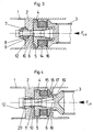
- FIGS. 1 and 2 there is a support bearing 2 between the coupling supports 1 of the vehicle underframe for mounting a coupling rod 3.
- the support bearing 2 is rigidly attached and receives a pull rod 6 arranged at the end of the coupling rod 3 in a central opening. Compression forces F LX in the coupling rod 3 act in the direction indicated.
- the coupling rod 3 itself has here at the end of its solid cross section a directional joint pressure plate 4, on which the pull rod 6 is arranged centrally in continuation of the central axis of the coupling rod 3.
- the directional joint pressure plate 4 carries on the pressure receiving side a spherical cap with a directional joint radius R-Ri, which is preferably a size dimension equal to or greater than half the length of the coupling rod, measured between the support bearings 2, since this results in an exactly spherical rolling behavior between the support surfaces, which is very low , in particular vertical wheel relief components and wheel flange - y forces. Furthermore, it is to be mentioned as advantageous that the tensioning torque which arises as a result of the axial displacement of the pull rod 6 relative to the support bearing 2 when the directional joint pressure plate 4 tilts during rolling on a rolling curve 5, a reduction in the y-forces between wheel and rail and a reduction in vertical wheel relief when a loaded and an empty wagon meet.
- the tension rod 6 is supported with play in a centering funnel 11 which continues in an opening funnel 12.
- the outer contours of the centering funnel 11 in the support bearing 2 and that of a centering stump part 10 of the pull rod 6 follow approximately a radius R A around the initial tipping points M2 and M3.
- a length dimension L2 of the centering funnel 11 is shorter by the distance of an angular dimension ⁇ of the maximum deflection of the coupling rod 3 than a length dimension L1 of the centering stub part 10.
- the centering stump part 10 is arranged on one side on the pressure receiving side and extends approximately to 1/3 of the support bearing thickness t. This results in a forced, centric tilting out of the directional joint pressure plate 4.
- the support bearing 2 has a ball joint attachment 8 and a tension plate 7 as a corresponding counterpart, which can move about an imaginary center tipping point M1.
- the traction sheave 7, which connects to a spring 13 for tensile forces, has 6 spherical contact surfaces in its seat on the pull rod for an inclined position of the coupling rod 3.
- the spring 13 ensures the possible axial displacement when the directional joint pressure plate 4 rolls up to its extreme tipping point for one backlash-free mounting of the entire joint, for longitudinal damping and for a smooth compensation of the movement processes that do not constantly move around the same tipping points during the tipping process.
- Fig. 3 shows an arrangement of springs 14 for impact forces on the Pressure receiving side, with the directional joint pressure plate 4 here on the pull rod 6 axially - is arranged longitudinally displaceable. For this purpose, it has a directional joint sleeve 16, which guarantees a stable sliding fit.
- the spring 14 ensures a backlash-free Bracing of the entire joint and axial-axial bearing.
- the Ball joint attachment 8 is designed as an interchangeable ball joint ring 9 which is made of material with advantageous friction behavior. It is conceivable to combine the solution shown in FIG. 1 with that in FIG. 3, whereby one advantageously achieves a train and shock absorption.
- a spring 15 is used, the is responsible for tensile and impact forces at the same time. This is achieved through the Arrangement of a thrust washer 17 in its outer contour with additional pull-swivel stops 18 corresponds to a tilting around the imaginary enable medium tipping point M1.
- a pressure sleeve 20 secures the transmission the forces during tensile loads.
- a pressure ring 19 is used to transmit traction.
Landscapes
- Engineering & Computer Science (AREA)
- Mechanical Engineering (AREA)
- Pivots And Pivotal Connections (AREA)
- Vibration Prevention Devices (AREA)
- Vehicle Body Suspensions (AREA)
- Reinforcement Elements For Buildings (AREA)
- Shafts, Cranks, Connecting Bars, And Related Bearings (AREA)
- Spinning Or Twisting Of Yarns (AREA)
- Vibration Dampers (AREA)
- Joining Of Building Structures In Genera (AREA)
- Discharge Heating (AREA)
Applications Claiming Priority (2)
| Application Number | Priority Date | Filing Date | Title |
|---|---|---|---|
| DE19944754A DE19944754B4 (de) | 1999-09-17 | 1999-09-17 | Zug-Druck-Kuppelstangeneinrichtung |
| DE19944754 | 1999-09-17 |
Publications (3)
| Publication Number | Publication Date |
|---|---|
| EP1086870A2 true EP1086870A2 (fr) | 2001-03-28 |
| EP1086870A3 EP1086870A3 (fr) | 2001-09-12 |
| EP1086870B1 EP1086870B1 (fr) | 2004-09-29 |
Family
ID=7922463
Family Applications (1)
| Application Number | Title | Priority Date | Filing Date |
|---|---|---|---|
| EP00250233A Expired - Lifetime EP1086870B1 (fr) | 1999-09-17 | 2000-07-13 | Dispositif du type traction-compression pour une barre d'attelage |
Country Status (6)
| Country | Link |
|---|---|
| EP (1) | EP1086870B1 (fr) |
| AT (1) | ATE277798T1 (fr) |
| CZ (1) | CZ294052B6 (fr) |
| DE (1) | DE19944754B4 (fr) |
| PL (1) | PL342529A1 (fr) |
| SK (1) | SK13602000A3 (fr) |
Cited By (6)
| Publication number | Priority date | Publication date | Assignee | Title |
|---|---|---|---|---|
| EP1247715A1 (fr) | 2001-04-03 | 2002-10-09 | Schwab Verkehrstechnik AG | Dispositif de tamponnement et de traction pour véhicules ferroviaires |
| EP1407953A1 (fr) * | 2002-10-04 | 2004-04-14 | Manfred Bartel | Articulation pour barres d'attelage de véhicule ferroviaires |
| EP1413493A1 (fr) * | 2002-10-26 | 2004-04-28 | Manfred Bartel | Dispositif d'amortissement du type traction-compression avec l'effet d'une articulation directionelle |
| WO2010000566A1 (fr) * | 2008-06-30 | 2010-01-07 | Siemens Aktiengesellschaft | Articulation orientable de plaque oscillante haute performance |
| CN104097657A (zh) * | 2014-07-28 | 2014-10-15 | 南车株洲电力机车有限公司 | 一种机车牵引装置及其车体牵引组件 |
| CN113911161A (zh) * | 2021-09-18 | 2022-01-11 | 株洲时代新材料科技股份有限公司 | 一种救援用车端牵引连接装置 |
Families Citing this family (5)
| Publication number | Priority date | Publication date | Assignee | Title |
|---|---|---|---|---|
| DE19944576C1 (de) | 1999-09-17 | 2001-05-10 | Dwa Deutsche Waggonbau Gmbh | Längenanpaßbare Kuppelstange |
| DE10202241C1 (de) * | 2002-01-21 | 2003-10-09 | Manfred Bartel | Hochleistungsrichtgelenk |
| DE10210059C1 (de) | 2002-03-08 | 2003-10-09 | Manfred Bartel | Kuppelstange |
| DE102005031598B4 (de) * | 2005-07-06 | 2015-04-02 | Siemens Aktiengesellschaft | Hochleistungsrichtgelenk |
| DE102007003331B4 (de) * | 2007-01-17 | 2009-10-01 | Siemens Ag | Vorrichtung zur gelenkigen Anbindung einer Kupplungsstange an ein Fahrzeug |
Citations (3)
| Publication number | Priority date | Publication date | Assignee | Title |
|---|---|---|---|---|
| DE2135472A1 (de) | 1971-07-15 | 1973-01-25 | Knorr Bremse Kg Berlin Und Mue | Zug- und stossvorrichtung fuer mittelpufferkupplungen |
| DE4118529A1 (de) | 1991-06-06 | 1992-12-10 | Niesky Waggonbau Gmbh | Zug- und stosseinrichtung fuer kurzgekuppelte schienenfahrzeuge |
| DE29900875U1 (de) | 1999-01-20 | 1999-04-01 | Eisenbahntechnik Halberstadt GmbH, 38820 Halberstadt | Zug- und Stoßeinrichtung für kurzgekuppelte Schienenfahrzeuge |
Family Cites Families (5)
| Publication number | Priority date | Publication date | Assignee | Title |
|---|---|---|---|---|
| DE702189C (de) * | 1932-10-19 | 1941-02-01 | Scharfenbergkupplung Akt Ges | Starre Lenkkupplungen fuer Fahrzeuge |
| US3854597A (en) * | 1973-07-30 | 1974-12-17 | Westinghouse Air Brake Co | Automatic hose connector for railway cars |
| US4555033A (en) * | 1983-10-03 | 1985-11-26 | Pullman Standard, Inc. | Slackless non-cushioned drawbar arrangement for railway car underframe |
| DE4024998A1 (de) * | 1990-08-07 | 1992-02-13 | Bergische Stahlindustrie | Gelenk bzw. anlenkung fuer eine universell schwenkbare kuppelstange |
| US5507400A (en) * | 1994-06-01 | 1996-04-16 | National Castings Incorporated | Slackless drawbar or coupler with swivel mounting |
-
1999
- 1999-09-17 DE DE19944754A patent/DE19944754B4/de not_active Expired - Fee Related
-
2000
- 2000-07-13 EP EP00250233A patent/EP1086870B1/fr not_active Expired - Lifetime
- 2000-07-13 AT AT00250233T patent/ATE277798T1/de not_active IP Right Cessation
- 2000-08-28 CZ CZ20003131A patent/CZ294052B6/cs not_active IP Right Cessation
- 2000-09-12 SK SK1360-2000A patent/SK13602000A3/sk unknown
- 2000-09-14 PL PL00342529A patent/PL342529A1/xx unknown
Patent Citations (3)
| Publication number | Priority date | Publication date | Assignee | Title |
|---|---|---|---|---|
| DE2135472A1 (de) | 1971-07-15 | 1973-01-25 | Knorr Bremse Kg Berlin Und Mue | Zug- und stossvorrichtung fuer mittelpufferkupplungen |
| DE4118529A1 (de) | 1991-06-06 | 1992-12-10 | Niesky Waggonbau Gmbh | Zug- und stosseinrichtung fuer kurzgekuppelte schienenfahrzeuge |
| DE29900875U1 (de) | 1999-01-20 | 1999-04-01 | Eisenbahntechnik Halberstadt GmbH, 38820 Halberstadt | Zug- und Stoßeinrichtung für kurzgekuppelte Schienenfahrzeuge |
Cited By (9)
| Publication number | Priority date | Publication date | Assignee | Title |
|---|---|---|---|---|
| EP1247715A1 (fr) | 2001-04-03 | 2002-10-09 | Schwab Verkehrstechnik AG | Dispositif de tamponnement et de traction pour véhicules ferroviaires |
| EP1407953A1 (fr) * | 2002-10-04 | 2004-04-14 | Manfred Bartel | Articulation pour barres d'attelage de véhicule ferroviaires |
| EP1413493A1 (fr) * | 2002-10-26 | 2004-04-28 | Manfred Bartel | Dispositif d'amortissement du type traction-compression avec l'effet d'une articulation directionelle |
| WO2010000566A1 (fr) * | 2008-06-30 | 2010-01-07 | Siemens Aktiengesellschaft | Articulation orientable de plaque oscillante haute performance |
| RU2471664C2 (ru) * | 2008-06-30 | 2013-01-10 | Сименс Акциенгезелльшафт | Высокомощный выравнивающий шарнир с качающейся плитой |
| US8714376B2 (en) | 2008-06-30 | 2014-05-06 | Siemens Aktiengesellschaft | Heavy-duty pivot plate adjusting joint |
| CN104097657A (zh) * | 2014-07-28 | 2014-10-15 | 南车株洲电力机车有限公司 | 一种机车牵引装置及其车体牵引组件 |
| CN113911161A (zh) * | 2021-09-18 | 2022-01-11 | 株洲时代新材料科技股份有限公司 | 一种救援用车端牵引连接装置 |
| CN113911161B (zh) * | 2021-09-18 | 2022-09-27 | 株洲时代新材料科技股份有限公司 | 一种救援用车端牵引连接装置 |
Also Published As
| Publication number | Publication date |
|---|---|
| SK13602000A3 (sk) | 2001-06-11 |
| CZ20003131A3 (en) | 2001-05-16 |
| DE19944754A1 (de) | 2001-03-29 |
| EP1086870B1 (fr) | 2004-09-29 |
| CZ294052B6 (cs) | 2004-09-15 |
| EP1086870A3 (fr) | 2001-09-12 |
| DE19944754B4 (de) | 2004-01-29 |
| PL342529A1 (en) | 2001-03-26 |
| ATE277798T1 (de) | 2004-10-15 |
Similar Documents
| Publication | Publication Date | Title |
|---|---|---|
| DE69501838T2 (de) | Gelenkige Kupplung und Verfahren zur Absorption von Energie zwischen zwei Eisenbahnfahrzeugen | |
| EP1312527B1 (fr) | Articulation d'accouplement | |
| DE2617896A1 (de) | Drehgestell fuer eisenbahnwagen | |
| DE10246428B4 (de) | Richtgelenk für Kuppelstangen | |
| EP1086870B1 (fr) | Dispositif du type traction-compression pour une barre d'attelage | |
| DE4213948A1 (de) | Schienenfahrzeug | |
| EP0944513A1 (fr) | Chassis de bogie pour materiel ferroviaire roulant | |
| WO2010000566A1 (fr) | Articulation orientable de plaque oscillante haute performance | |
| DE69002686T2 (de) | Drehgestellkonstruktion für ein Eisenbahnfahrzeug. | |
| EP1946988B1 (fr) | Dispositif de liaison articulée d'une barre d'attelage sur un véhicule | |
| DE2514304A1 (de) | Drehgestell fuer ein schienenfahrzeug | |
| DE10210059C1 (de) | Kuppelstange | |
| EP0046457B1 (fr) | Bogie à quatre essieux de véhicules ferroviaires à plate-forme surbaissée | |
| EP1407954B1 (fr) | Barre d'accouplement avec articulations dans des unités de wagons porteurs ferroviaires | |
| EP0915001B1 (fr) | Connexion entre caisses des wagons | |
| DE19703701C2 (de) | Zweiachsiges Fahrwerk für schienengebundene Transportsysteme | |
| EP1084929B1 (fr) | Barre d'attelage réglable en longueur | |
| EP0871581B1 (fr) | Bogie de vehicule ferroviaire a deux essieux | |
| EP0779194B1 (fr) | Rame ferroviaire automotrice formée d'au moins deux unités de voiture | |
| DE4132048C2 (fr) | ||
| DE10202241C1 (de) | Hochleistungsrichtgelenk | |
| EP1674367B1 (fr) | Dispositif pour la liaison articulée de deux caisses d'un véhicule ferroviaire à sections multiples | |
| EP1897776B1 (fr) | Bogie | |
| DE10305937A1 (de) | Kuppelstange mit extremer Längenanpassbarkeit | |
| DE29720120U1 (de) | Fahrwerk für Schienenfahrzeuge |
Legal Events
| Date | Code | Title | Description |
|---|---|---|---|
| PUAI | Public reference made under article 153(3) epc to a published international application that has entered the european phase |
Free format text: ORIGINAL CODE: 0009012 |
|
| AK | Designated contracting states |
Kind code of ref document: A2 Designated state(s): AT BE CH CY DE DK ES FI FR GB GR IE IT LI LU MC NL PT SE Kind code of ref document: A2 Designated state(s): AT CH FI FR GB IT LI |
|
| AX | Request for extension of the european patent |
Free format text: AL;LT;LV;MK;RO;SI |
|
| PUAL | Search report despatched |
Free format text: ORIGINAL CODE: 0009013 |
|
| AK | Designated contracting states |
Kind code of ref document: A3 Designated state(s): AT BE CH CY DE DK ES FI FR GB GR IE IT LI LU MC NL PT SE |
|
| AX | Request for extension of the european patent |
Free format text: AL;LT;LV;MK;RO;SI |
|
| 17P | Request for examination filed |
Effective date: 20020205 |
|
| AKX | Designation fees paid |
Free format text: AT BE CH CY DE DK LI |
|
| RBV | Designated contracting states (corrected) |
Designated state(s): AT CH FI FR GB IT LI |
|
| REG | Reference to a national code |
Ref country code: DE Ref legal event code: 8566 |
|
| 17Q | First examination report despatched |
Effective date: 20020717 |
|
| GRAP | Despatch of communication of intention to grant a patent |
Free format text: ORIGINAL CODE: EPIDOSNIGR1 |
|
| GRAS | Grant fee paid |
Free format text: ORIGINAL CODE: EPIDOSNIGR3 |
|
| GRAA | (expected) grant |
Free format text: ORIGINAL CODE: 0009210 |
|
| AK | Designated contracting states |
Kind code of ref document: B1 Designated state(s): AT CH FI FR GB IT LI |
|
| REG | Reference to a national code |
Ref country code: GB Ref legal event code: FG4D Free format text: NOT ENGLISH |
|
| REG | Reference to a national code |
Ref country code: CH Ref legal event code: EP |
|
| RAP2 | Party data changed (patent owner data changed or rights of a patent transferred) |
Owner name: BOMBARDIER TRANSPORTATION (BAHNTECHNOLOGIE) HOLDIN Owner name: BARTEL, MANFRED |
|
| REG | Reference to a national code |
Ref country code: CH Ref legal event code: NV Representative=s name: A. BRAUN, BRAUN, HERITIER, ESCHMANN AG PATENTANWAE |
|
| GBT | Gb: translation of ep patent filed (gb section 77(6)(a)/1977) |
Effective date: 20050307 |
|
| PG25 | Lapsed in a contracting state [announced via postgrant information from national office to epo] |
Ref country code: FI Free format text: LAPSE BECAUSE OF NON-PAYMENT OF DUE FEES Effective date: 20050710 |
|
| PG25 | Lapsed in a contracting state [announced via postgrant information from national office to epo] |
Ref country code: IT Free format text: LAPSE BECAUSE OF NON-PAYMENT OF DUE FEES;WARNING: LAPSES OF ITALIAN PATENTS WITH EFFECTIVE DATE BEFORE 2007 MAY HAVE OCCURRED AT ANY TIME BEFORE 2007. THE CORRECT EFFECTIVE DATE MAY BE DIFFERENT FROM THE ONE RECORDED. Effective date: 20050713 Ref country code: AT Free format text: LAPSE BECAUSE OF NON-PAYMENT OF DUE FEES Effective date: 20050713 Ref country code: GB Free format text: LAPSE BECAUSE OF NON-PAYMENT OF DUE FEES Effective date: 20050713 |
|
| PG25 | Lapsed in a contracting state [announced via postgrant information from national office to epo] |
Ref country code: LI Free format text: LAPSE BECAUSE OF NON-PAYMENT OF DUE FEES Effective date: 20050731 Ref country code: CH Free format text: LAPSE BECAUSE OF NON-PAYMENT OF DUE FEES Effective date: 20050731 |
|
| PLBE | No opposition filed within time limit |
Free format text: ORIGINAL CODE: 0009261 |
|
| STAA | Information on the status of an ep patent application or granted ep patent |
Free format text: STATUS: NO OPPOSITION FILED WITHIN TIME LIMIT |
|
| 26N | No opposition filed |
Effective date: 20050630 |
|
| ET | Fr: translation filed | ||
| REG | Reference to a national code |
Ref country code: CH Ref legal event code: PL |
|
| GBPC | Gb: european patent ceased through non-payment of renewal fee |
Effective date: 20050713 |
|
| PG25 | Lapsed in a contracting state [announced via postgrant information from national office to epo] |
Ref country code: FR Free format text: LAPSE BECAUSE OF NON-PAYMENT OF DUE FEES Effective date: 20060331 |
|
| REG | Reference to a national code |
Ref country code: FR Ref legal event code: ST Effective date: 20060331 |