EP1087093A2 - Volet roulant pour ouvertures de bâtiments, et dont la forme diffère de la forme rectangulaire - Google Patents
Volet roulant pour ouvertures de bâtiments, et dont la forme diffère de la forme rectangulaire Download PDFInfo
- Publication number
- EP1087093A2 EP1087093A2 EP00119416A EP00119416A EP1087093A2 EP 1087093 A2 EP1087093 A2 EP 1087093A2 EP 00119416 A EP00119416 A EP 00119416A EP 00119416 A EP00119416 A EP 00119416A EP 1087093 A2 EP1087093 A2 EP 1087093A2
- Authority
- EP
- European Patent Office
- Prior art keywords
- slats
- guide rail
- slat
- roller shutter
- short
- Prior art date
- Legal status (The legal status is an assumption and is not a legal conclusion. Google has not performed a legal analysis and makes no representation as to the accuracy of the status listed.)
- Granted
Links
- 238000004804 winding Methods 0.000 claims abstract description 56
- 241000446313 Lamella Species 0.000 claims abstract description 39
- 230000005484 gravity Effects 0.000 claims description 4
- 230000003247 decreasing effect Effects 0.000 claims 1
- 210000001331 nose Anatomy 0.000 description 11
- 238000004519 manufacturing process Methods 0.000 description 3
- 238000011161 development Methods 0.000 description 2
- 230000018109 developmental process Effects 0.000 description 2
- 238000000034 method Methods 0.000 description 2
- 206010038743 Restlessness Diseases 0.000 description 1
- 238000005253 cladding Methods 0.000 description 1
- 230000001447 compensatory effect Effects 0.000 description 1
- 238000006073 displacement reaction Methods 0.000 description 1
- 238000009434 installation Methods 0.000 description 1
- 239000002184 metal Substances 0.000 description 1
Images


Classifications
-
- E—FIXED CONSTRUCTIONS
- E06—DOORS, WINDOWS, SHUTTERS, OR ROLLER BLINDS IN GENERAL; LADDERS
- E06B—FIXED OR MOVABLE CLOSURES FOR OPENINGS IN BUILDINGS, VEHICLES, FENCES OR LIKE ENCLOSURES IN GENERAL, e.g. DOORS, WINDOWS, BLINDS, GATES
- E06B9/00—Screening or protective devices for wall or similar openings, with or without operating or securing mechanisms; Closures of similar construction
- E06B9/56—Operating, guiding or securing devices or arrangements for roll-type closures; Spring drums; Tape drums; Counterweighting arrangements therefor
- E06B9/58—Guiding devices
-
- E—FIXED CONSTRUCTIONS
- E06—DOORS, WINDOWS, SHUTTERS, OR ROLLER BLINDS IN GENERAL; LADDERS
- E06B—FIXED OR MOVABLE CLOSURES FOR OPENINGS IN BUILDINGS, VEHICLES, FENCES OR LIKE ENCLOSURES IN GENERAL, e.g. DOORS, WINDOWS, BLINDS, GATES
- E06B9/00—Screening or protective devices for wall or similar openings, with or without operating or securing mechanisms; Closures of similar construction
- E06B9/02—Shutters, movable grilles, or other safety closing devices, e.g. against burglary
- E06B9/08—Roll-type closures
- E06B9/11—Roller shutters
- E06B9/15—Roller shutters with closing members formed of slats or the like
-
- E—FIXED CONSTRUCTIONS
- E06—DOORS, WINDOWS, SHUTTERS, OR ROLLER BLINDS IN GENERAL; LADDERS
- E06B—FIXED OR MOVABLE CLOSURES FOR OPENINGS IN BUILDINGS, VEHICLES, FENCES OR LIKE ENCLOSURES IN GENERAL, e.g. DOORS, WINDOWS, BLINDS, GATES
- E06B9/00—Screening or protective devices for wall or similar openings, with or without operating or securing mechanisms; Closures of similar construction
- E06B9/24—Screens or other constructions affording protection against light, especially against sunshine; Similar screens for privacy or appearance; Slat blinds
- E06B2009/2482—Special shape
- E06B2009/2494—Trapezoidal or triangular
Definitions
- the invention relates to a roller shutter for the Rectangular shape, different shapes of building openings, in particular for trapezoidal building openings, according to the generic term of claim 1.
- roller shutter Such a roller shutter is known from DE 38 06 893 C2.
- the known roller shutter comprises a longer and a shorter guide rail, at the ends of each one the diagonally arranged Winding shaft bearing plate is arranged.
- the roller shutter curtain consists of articulated metal and plastic profiles and points because of the obliquely arranged winding shaft next to slats extending across the entire opening width also short slats that do not extend across the entire opening width extend and with its lower end at the bottom of the Panzer end free.
- sliding bodies are provided which have a slot in the reach behind the longer guide rail.
- the guide rail continues to support the short slats
- tape that can be wrapped between the armor windings trained support device is provided, the support device connected to the bearing plate and parallel to the bearing plate running band edge serves as a supporting edge for the sliding body.
- the short lamellas are supported the underlying, radially adjacent slats by in addition to the lamella lugs in the area of their guide rail side Ends and their mutually facing sides a surface profile with one another in the wound state engaging grooves running transversely to the slat axis and have webs.
- the disadvantage is that of the lamella surface protruding and in the field of surface profiling arranged sliding body the mutual engagement of the can interfere with assigned surface profiles and as a result evasive and offset movements of the slats e.g. take place in the longitudinal direction of the slats. This can result in drive losses and a restless roller shutter run result.
- the sliding bodies of the short blades are in the wound state on the adjacent one Slat of the next inner winding layer in a defined positional relationship supports. For this purpose, these sliding bodies grip the neighboring one Insert the slat of the next inner winding layer into elongated holes, which are formed in the longitudinal surfaces of the slats. Because of the in Circumferential direction of the winding shaft limited extension of the Elongated holes can occur, for example, due to manufacturing tolerances happen that when winding up the roller shutter curtain on the Winding shaft do not hit the sliding bodies exactly in the elongated holes. Then there is no support for the outer lamellae on the underlying slats instead, whereupon those due to their weight can slip off. This would, however, become troubled Run the roller shutter.
- the support edge Since the support edge is not as in the prior art by the Edge of a closed opening but through the free edge the slat end is formed, the influence of manufacturing tolerances on the system security of the sliding body on the supporting edge much less.
- the support edge extends at least in the long slats over the entire slat width, which means with respect to each other on the winding in the circumferential direction arbitrarily offset slats ensures that actually a sliding body of a short lamella on the outside the edge of a long internal slat comes to rest. On the other hand, this results in a displacement of the slats in the circumferential direction the armored winding possible. As a result, can Compensatory movements take place between the slats and squeezes be avoided.
- the projecting sliding bodies are and the paragraphs assigned to each other such that the end faces the slat ends on the guide rail side in one preferably aligned flush with the bearing plate parallel plane are.
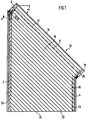
- roller shutter designated as a whole in Figure 1 according to a preferred embodiment, it is a trapezoidal shutters for so-called studio windows with a horizontal one lower edge of the window, two verticals of different lengths Window edges and one inclined at an angle ⁇ , parallel upper window edge running to the roof slope.
- the roller shutter 1 accordingly comprises one longer (left) guide rail 2 and a shorter (right) guide rail 4 and one arranged obliquely according to the roof pitch ⁇ and winding shaft 6 indicated by a broken line, between two at the upper ends of the guide rails 2, 4th hinged bearing plates 8, 10 is rotatably and drivably mounted.
- the winding shaft 6 is preferably with a profile bar polygonal cross section.
- the two bearing plates 8, 10 form together with the winding shaft 6 and side cladding plates a roller shutter box 12.
- the upper end is one of any Number of interlocking, preferably formed as hollow profiles lamella 14 Roller shutter curtain 16 attached, the slats 14 both when open as with closed roller shutter 1 parallel to the upper one Window edge arranged and therefore also at an angle ⁇ are inclined to the horizontal.
- the roller shutter curtain is 16 can be wound onto the winding shaft 6 as a spiral armored winding 17.
- the upper ones extend Slats 18 over the entire window width and are with their ends guided in both guide rails 2, 4 during the slats below the last one, which extends across the entire width of the window Slat 20 are designed as short slats 22 and only with its left end in the longer (left) guide rail 2 are guided and with their bevelled right ends the horizontal bottom edge 24 of the roller shutter 16 form free ends.
- the right ends are the slats 18 extending over the entire window width with in one Run slot of the shorter (right) guide rail 4 guided Slide shoes 26 provided, which preferably as the side in the Hollow profiles inserted plastic body are formed.
- the Sliding shoes 26 slide during the winding process of the roller shutter curtain 16 on the winding shaft 6 after exiting the slot the shorter (right) guide rail 4 on this guide rail 4 assigned right bearing plate 10 in a spiral Track and consequently support the slats 18 on the right bearing plate 10 against the acting in the longitudinal direction of the slats Component of gravity.
- the sliding shoes 26 are rounded on the end face, so that the slats 18 within a large Angle range take any angle ⁇ to the horizontal can without risk of wear and friction run on an edge.
- the guide rail-side (left) slat ends 29 of the Short lamellae 22 are preferably perpendicular to at least one Slat plane extending, a leading edge 28 of the longer (left) guide strip 2 provided lamella nose 30, through which the short blades 22 on the longer (left) guide bar 2 are held in a form-fitting manner, as in FIGS. 3 and 6 emerges.
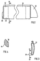
- the lamella lugs 30 project beyond the adjacent lamella surface and are molded on plate-shaped plastic bodies 32, which is inserted laterally into the rectangular hollow profiles are (Fig.2), and preferably in the of the guide rail 2 on the nearest corner of an inclined installation position Short lamella 22 arranged.
- the pin-shaped lamella noses 30 therefore form rotating poles around which the short blades 22 in the level of the roller shutter 16 can be pivoted.
- the slats are 18, the plastic body 32 and the slide shoes 26 for adjustment to the armored winding 17 slightly arched.
- FIG. 4 is the cross-sectional profile of a lamella nose 30 approximately circular segment-shaped, with that of the leading edge 28 of the Guide rail 2 facing surface 34 formed in a circular arc is, so that this also results in a large number of low-friction Given angular positions relative to the leading edge 28 is.
- Fig.5 shows, they have the entire window width extending, longer slats 18 on their guide rail side left slat end 29 an inserted plastic body 33, but which has no lamella nose 30, because these slats 18 already through their sliding shoes 26 in the shorter Support the (right) guide rail 4.
- the longer (left) guide rail 2 and the shorter (right) Guide rail 4 formed as a hollow profile and each include one based on the width of the roller shutter curtain 16 outer guide channel 36 and an inner, from the roller shutter curtain 16 through a Opening 38 accessible chamber 40, being between the outer Guide channel 36 and the inner chamber 40 in the longitudinal direction of the guide rail extending slot 42 is present.
- an additional weight 44 are longitudinally displaceable, are in the inner chamber 40 multi-groove inserts 46, preferably made of PVC, are fitted, which on the side surfaces are in the longitudinal direction of the guide rail 2 extending in the plane of the roller shutter curtain 16 seen in a line one behind the other guide grooves 49 have, the groove edges of which are encompassed by the lamella lugs 30 Represent leading edges 50 for the short lamellae 22 that can protrude through the opening 38 into the interior of the chamber 40.
- the lamella lugs 30 protrude vertically, for example, into an outer guide groove 48 of the preferably three guide grooves 49 into each other on the two side surfaces of the chamber 40 oppositely distributed symmetrically around the guide rail 2 can be used universally, e.g. also for a roller shutter, its longer guide rail arranged on the right side is.
- the multi-groove PVC inserts 46 as Can be used for additional slide-in parts, e.g. for one Sliding insert for guiding the lamella sliding shoes 26 in the shorter one (right) guide rail.
- the left bearing plate 8 is by means of an articulated connection, preferably by a hinge joint 52 on the top End 54 of the longer (left) guide rail 2 adjustable inclination held, with the hinge axis of rotation 56 substantially runs horizontally and perpendicular to the winding shaft 6.
- the face 62 of the longer (left) guide rail 2 is corresponding to the Inclination ⁇ of the winding shaft 6 beveled, preferably by a oblique saw cut.
- the shorter (right) guide rail 4 is on the right bearing plate 10 also by means of an articulated connection attached so that the inclination of the entire shutter box 12 relative to the guide rails 2, 4 corresponding to the just present sloping roof is adjustable.
- Support device 64 is provided.
- the support device 64 contains an arched strip 66, the winding shaft end of which is parallel is arranged to the bearing plate 8.
- the slats 18, 22 are after leaving the Support device 64 on the winding shaft 6 as a spiral armored winding 17 wound, the lamella tabs 30 of the short lamellae 22 preferably radially inwards, towards the winding shaft 6 point.
- the inner windings 68 contain only unabridged ones Slats extending over the entire width of the window opening 18, while the adjoining outer windings 70 consist exclusively of short lamellae 22.
- 7 is only the innermost winding 68 with unabridged lamellae 18 shown.
- the lamellar lugs 30 are on the radial inner edge 72 of the guide rail-side slat end 29 of the short lamellae 22 and point radially inwards.
- the lamella lugs 30 On the from the side 74 facing the lamella nose 30 are the lamella lugs 30 with these at least in the longitudinal direction of the slats covering areas 76 drawn in with respect to the lamella plane assigned to the adjacent inner slats, which are around short lamellae 22 and at least those in the wound state innermost winding 68 of the short lamellae 22, uncut Slats 18 can act. Preferably all have uncut slats 18 over such a retracted area 76.
- the retracted area is used to accommodate the radial inside protruding lamellar lugs 30 of the adjacent outer Short blades 22 and is in each case as a paragraph 76 on the radially outer Edge 78 of the slat end 29 on the guide rail side educated.
- the paragraph 76 forms a support edge for those engaging in it Lamellar lugs 30 of the outer one in contact with the winding Short lamellae 22 to release them from the armored winding 17 avoid.
- the shoulders 76 have a height h, which is preferably slight is smaller than the length l of the lamella lugs 30. Alternatively these dimensions can also be the same size or h is slight larger than l.
- the width b of the paragraphs 76 preferably corresponds the diameter d of the lamellar noses engaging in them 30th
- the shoulders 76 preferably extend over the entire width of the slats 18, 22 and all the slats 18, 22 extend the same Because of this, they always have at least one lamella nose 30 an outer short lamella 22 in paragraph 76 one in the armored winding 17 adjacent short lamella 22 or unabridged lamella 18, so that it is ensured that all short lamellae 22 are supported in the wound state are.
- the lamella lugs 30 of the short lamellae 22 instead of radially inwards as shown in FIG also protrude radially outwards, in which case the shoulders 76 point radially inward and the innermost when wound up Winding 68 of short lamellae 22 receiving uncut lamellae 18 with a lamella nose 30 pointing radially outwards must be provided.
- the shoulders 76 are preferably made of plastic, plate-shaped plastic bodies 33 formed, which in the slat ends 29 on the guide rail side as hollow profiles trained uncut slats 18 are inserted.
- the plastic body 32 of the short lamellae 22 have additionally on that of the paragraph 76 pioneering side formed the lamella nose 30.
Landscapes
- Engineering & Computer Science (AREA)
- Structural Engineering (AREA)
- Architecture (AREA)
- Civil Engineering (AREA)
- Operating, Guiding And Securing Of Roll- Type Closing Members (AREA)
- Specific Sealing Or Ventilating Devices For Doors And Windows (AREA)
- Finishing Walls (AREA)
Applications Claiming Priority (8)
| Application Number | Priority Date | Filing Date | Title |
|---|---|---|---|
| DE1999145905 DE19945905C1 (de) | 1999-09-24 | 1999-09-24 | Rolladen für von der Rechteckform abweichende Formen von Gebäudeöffnungen |
| DE19945906 | 1999-09-24 | ||
| DE19945905 | 1999-09-24 | ||
| DE1999145908 DE19945908C2 (de) | 1999-09-24 | 1999-09-24 | Rolladen für von der Rechteckform abweichende Formen von Gebäudeöffnungen |
| DE19945906 | 1999-09-24 | ||
| DE19945908 | 1999-09-24 | ||
| DE20005831U | 2000-03-29 | ||
| DE20005831U DE20005831U1 (de) | 1999-09-24 | 2000-03-29 | Rolladen für von der Rechteckform abweichende Formen von Gebäudeöffnungen |
Publications (3)
| Publication Number | Publication Date |
|---|---|
| EP1087093A2 true EP1087093A2 (fr) | 2001-03-28 |
| EP1087093A3 EP1087093A3 (fr) | 2003-01-29 |
| EP1087093B1 EP1087093B1 (fr) | 2005-11-09 |
Family
ID=27438987
Family Applications (2)
| Application Number | Title | Priority Date | Filing Date |
|---|---|---|---|
| EP00119417A Expired - Lifetime EP1087094B1 (fr) | 1999-09-24 | 2000-09-13 | Volet roulant pour ouvertures de bâtiments, et dont la forme diffère de la forme rectangulaire |
| EP00119416A Expired - Lifetime EP1087093B1 (fr) | 1999-09-24 | 2000-09-13 | Volet roulant pour ouvertures de bâtiments, et dont la forme diffère de la forme rectangulaire |
Family Applications Before (1)
| Application Number | Title | Priority Date | Filing Date |
|---|---|---|---|
| EP00119417A Expired - Lifetime EP1087094B1 (fr) | 1999-09-24 | 2000-09-13 | Volet roulant pour ouvertures de bâtiments, et dont la forme diffère de la forme rectangulaire |
Country Status (3)
| Country | Link |
|---|---|
| EP (2) | EP1087094B1 (fr) |
| AT (1) | ATE309445T1 (fr) |
| DE (1) | DE50011552D1 (fr) |
Families Citing this family (1)
| Publication number | Priority date | Publication date | Assignee | Title |
|---|---|---|---|---|
| GB2502039B (en) * | 2012-02-29 | 2017-11-15 | Ideas By Design Ltd | Apparatus for mounting a screen guide rail |
Citations (2)
| Publication number | Priority date | Publication date | Assignee | Title |
|---|---|---|---|---|
| DE3806893C2 (de) | 1988-03-03 | 1996-06-20 | Reflexa Werke H P Albrecht | Rolladen |
| DE19547587A1 (de) | 1995-12-20 | 1997-07-03 | Guenter Degendorfer | Rolladen |
Family Cites Families (2)
| Publication number | Priority date | Publication date | Assignee | Title |
|---|---|---|---|---|
| DE2707467C2 (de) * | 1977-02-21 | 1987-01-08 | Kurt 7336 Uhingen Jüngling | Rolladen für Fenster und Türen mit schräg verlaufendem oberem Rahmenteil |
| DE3725380A1 (de) | 1987-07-31 | 1989-02-09 | Reflexa Werke H P Albrecht | Rolladen |
-
2000
- 2000-09-13 EP EP00119417A patent/EP1087094B1/fr not_active Expired - Lifetime
- 2000-09-13 AT AT00119416T patent/ATE309445T1/de not_active IP Right Cessation
- 2000-09-13 EP EP00119416A patent/EP1087093B1/fr not_active Expired - Lifetime
- 2000-09-13 DE DE50011552T patent/DE50011552D1/de not_active Expired - Lifetime
Patent Citations (2)
| Publication number | Priority date | Publication date | Assignee | Title |
|---|---|---|---|---|
| DE3806893C2 (de) | 1988-03-03 | 1996-06-20 | Reflexa Werke H P Albrecht | Rolladen |
| DE19547587A1 (de) | 1995-12-20 | 1997-07-03 | Guenter Degendorfer | Rolladen |
Also Published As
| Publication number | Publication date |
|---|---|
| EP1087094A2 (fr) | 2001-03-28 |
| EP1087093B1 (fr) | 2005-11-09 |
| EP1087094B1 (fr) | 2009-06-10 |
| EP1087094A3 (fr) | 2003-02-05 |
| ATE309445T1 (de) | 2005-11-15 |
| DE50011552D1 (de) | 2005-12-15 |
| EP1087093A3 (fr) | 2003-01-29 |
Similar Documents
| Publication | Publication Date | Title |
|---|---|---|
| DE69519764T2 (de) | Jalousierbarer Rolladen | |
| EP0338362B1 (fr) | Dispositif de protection solaire | |
| EP3176355B1 (fr) | Volet roulant | |
| DE19652577C2 (de) | Sektionaltor zum Verschließen einer Wandöffnung | |
| EP0780542A2 (fr) | Mécanisme d'entraînement de volets roulants, notamment pour systèmes de protection solaire | |
| EP2923024B1 (fr) | Dispositif de couverture | |
| DE2623359A1 (de) | Verschlussvorrichtung | |
| DE3806893C2 (de) | Rolladen | |
| DE19854552C2 (de) | Rolladenkasten mit Wärmedämmkörper | |
| AT397283B (de) | Rolladen | |
| DE19945905C1 (de) | Rolladen für von der Rechteckform abweichende Formen von Gebäudeöffnungen | |
| DE69715451T2 (de) | Rolladen | |
| EP1087093B1 (fr) | Volet roulant pour ouvertures de bâtiments, et dont la forme diffère de la forme rectangulaire | |
| DE19964284C2 (de) | Rolladen für von der Rechteckform abweichende Formen von Gebäudeöffnungen | |
| DE19649024B4 (de) | Rolladen | |
| EP3845736A1 (fr) | Dispositif de verrouillage, dispositif de store à lamelles et procédé de fonctionnement du dispositif de verrouillage | |
| EP4446556B1 (fr) | Dispositif d'ombrage d'une ouverture de bâtiment et rail de guidage latéral associé | |
| CH696275A5 (de) | Raffstore mit Wendelager. | |
| DE3346124C2 (de) | Schrägrolladen | |
| EP1128019A2 (fr) | Cloison de séparation mobile | |
| DE3313467A1 (de) | Lamellen-laden | |
| AT363239B (de) | Rafflamellenstore | |
| DE20110433U1 (de) | Rollladen-Schutz gegen Klappern | |
| DE202004004863U1 (de) | Rolladen für von der Rechteckform abweichende Formen von Gebäudeöffnungen | |
| DE202015002105U1 (de) | Schrägrolladen für Schrägfenster |
Legal Events
| Date | Code | Title | Description |
|---|---|---|---|
| PUAI | Public reference made under article 153(3) epc to a published international application that has entered the european phase |
Free format text: ORIGINAL CODE: 0009012 |
|
| 17P | Request for examination filed |
Effective date: 20000913 |
|
| AK | Designated contracting states |
Kind code of ref document: A2 Designated state(s): AT BE CH CY DE DK ES FI FR GB GR IE IT LI LU MC NL PT SE |
|
| AX | Request for extension of the european patent |
Free format text: AL;LT;LV;MK;RO;SI |
|
| PUAL | Search report despatched |
Free format text: ORIGINAL CODE: 0009013 |
|
| AK | Designated contracting states |
Designated state(s): AT BE CH CY DE DK ES FI FR GB GR IE IT LI LU MC NL PT SE |
|
| AX | Request for extension of the european patent |
Extension state: AL LT LV MK RO SI |
|
| RIC1 | Information provided on ipc code assigned before grant |
Ipc: 7E 06B 9/15 B Ipc: 7E 06B 9/58 A |
|
| AKX | Designation fees paid |
Designated state(s): AT BE CH DE FR LI NL |
|
| GRAP | Despatch of communication of intention to grant a patent |
Free format text: ORIGINAL CODE: EPIDOSNIGR1 |
|
| GRAS | Grant fee paid |
Free format text: ORIGINAL CODE: EPIDOSNIGR3 |
|
| GRAA | (expected) grant |
Free format text: ORIGINAL CODE: 0009210 |
|
| AK | Designated contracting states |
Kind code of ref document: B1 Designated state(s): AT BE CH DE FR LI NL |
|
| PG25 | Lapsed in a contracting state [announced via postgrant information from national office to epo] |
Ref country code: NL Free format text: LAPSE BECAUSE OF FAILURE TO SUBMIT A TRANSLATION OF THE DESCRIPTION OR TO PAY THE FEE WITHIN THE PRESCRIBED TIME-LIMIT Effective date: 20051109 |
|
| REG | Reference to a national code |
Ref country code: CH Ref legal event code: EP |
|
| REF | Corresponds to: |
Ref document number: 50011552 Country of ref document: DE Date of ref document: 20051215 Kind code of ref document: P |
|
| NLV1 | Nl: lapsed or annulled due to failure to fulfill the requirements of art. 29p and 29m of the patents act | ||
| ET | Fr: translation filed | ||
| PLBE | No opposition filed within time limit |
Free format text: ORIGINAL CODE: 0009261 |
|
| STAA | Information on the status of an ep patent application or granted ep patent |
Free format text: STATUS: NO OPPOSITION FILED WITHIN TIME LIMIT |
|
| PG25 | Lapsed in a contracting state [announced via postgrant information from national office to epo] |
Ref country code: CH Free format text: LAPSE BECAUSE OF NON-PAYMENT OF DUE FEES Effective date: 20060930 Ref country code: LI Free format text: LAPSE BECAUSE OF NON-PAYMENT OF DUE FEES Effective date: 20060930 Ref country code: BE Free format text: LAPSE BECAUSE OF NON-PAYMENT OF DUE FEES Effective date: 20060930 |
|
| 26N | No opposition filed |
Effective date: 20060810 |
|
| REG | Reference to a national code |
Ref country code: CH Ref legal event code: PL |
|
| PG25 | Lapsed in a contracting state [announced via postgrant information from national office to epo] |
Ref country code: AT Free format text: LAPSE BECAUSE OF NON-PAYMENT OF DUE FEES Effective date: 20060913 |
|
| BERE | Be: lapsed |
Owner name: ROMA ROLLADENSYSTEME G.M.B.H. Effective date: 20060930 |
|
| REG | Reference to a national code |
Ref country code: FR Ref legal event code: CD Owner name: ROMA KG, DE Effective date: 20120111 |
|
| REG | Reference to a national code |
Ref country code: DE Ref legal event code: R082 Ref document number: 50011552 Country of ref document: DE Representative=s name: MARKUS WIEDEMANN, DE |
|
| REG | Reference to a national code |
Ref country code: DE Ref legal event code: R081 Ref document number: 50011552 Country of ref document: DE Owner name: ROMA KG, DE Free format text: FORMER OWNER: ROMA ROLLADENSYSTEME GMBH, 89331 BURGAU, DE Effective date: 20120410 Ref country code: DE Ref legal event code: R082 Ref document number: 50011552 Country of ref document: DE Representative=s name: WIEDEMANN, MARKUS, DIPL.-ING.UNIV. DR.-ING., DE Effective date: 20120410 |
|
| PGFP | Annual fee paid to national office [announced via postgrant information from national office to epo] |
Ref country code: FR Payment date: 20121008 Year of fee payment: 13 |
|
| REG | Reference to a national code |
Ref country code: FR Ref legal event code: ST Effective date: 20140530 |
|
| PG25 | Lapsed in a contracting state [announced via postgrant information from national office to epo] |
Ref country code: FR Free format text: LAPSE BECAUSE OF NON-PAYMENT OF DUE FEES Effective date: 20130930 |
|
| REG | Reference to a national code |
Ref country code: DE Ref legal event code: R084 Ref document number: 50011552 Country of ref document: DE |
|
| PGFP | Annual fee paid to national office [announced via postgrant information from national office to epo] |
Ref country code: DE Payment date: 20190906 Year of fee payment: 20 |
|
| REG | Reference to a national code |
Ref country code: DE Ref legal event code: R071 Ref document number: 50011552 Country of ref document: DE |