EP1087094A2 - Volet roulant pour ouvertures de bâtiments, et dont la forme diffère de la forme rectangulaire - Google Patents
Volet roulant pour ouvertures de bâtiments, et dont la forme diffère de la forme rectangulaire Download PDFInfo
- Publication number
- EP1087094A2 EP1087094A2 EP00119417A EP00119417A EP1087094A2 EP 1087094 A2 EP1087094 A2 EP 1087094A2 EP 00119417 A EP00119417 A EP 00119417A EP 00119417 A EP00119417 A EP 00119417A EP 1087094 A2 EP1087094 A2 EP 1087094A2
- Authority
- EP
- European Patent Office
- Prior art keywords
- guide
- roller shutter
- guide rail
- winding shaft
- slat
- Prior art date
- Legal status (The legal status is an assumption and is not a legal conclusion. Google has not performed a legal analysis and makes no representation as to the accuracy of the status listed.)
- Granted
Links
- 238000004804 winding Methods 0.000 claims abstract description 80
- 241000446313 Lamella Species 0.000 claims abstract description 56
- 230000007704 transition Effects 0.000 claims description 11
- 230000005484 gravity Effects 0.000 claims description 5
- 238000000034 method Methods 0.000 claims description 5
- 230000008569 process Effects 0.000 claims description 4
- 230000005489 elastic deformation Effects 0.000 claims description 3
- 238000007789 sealing Methods 0.000 claims 1
- 210000001331 nose Anatomy 0.000 description 10
- 238000004519 manufacturing process Methods 0.000 description 7
- 230000008859 change Effects 0.000 description 2
- 230000001419 dependent effect Effects 0.000 description 2
- NJPPVKZQTLUDBO-UHFFFAOYSA-N novaluron Chemical compound C1=C(Cl)C(OC(F)(F)C(OC(F)(F)F)F)=CC=C1NC(=O)NC(=O)C1=C(F)C=CC=C1F NJPPVKZQTLUDBO-UHFFFAOYSA-N 0.000 description 2
- 241001433879 Camarea Species 0.000 description 1
- 230000006978 adaptation Effects 0.000 description 1
- 230000009286 beneficial effect Effects 0.000 description 1
- 238000005253 cladding Methods 0.000 description 1
- 238000005520 cutting process Methods 0.000 description 1
- 238000011161 development Methods 0.000 description 1
- 230000018109 developmental process Effects 0.000 description 1
- 230000000694 effects Effects 0.000 description 1
- 238000009434 installation Methods 0.000 description 1
- 210000001503 joint Anatomy 0.000 description 1
- 230000009191 jumping Effects 0.000 description 1
- 239000002184 metal Substances 0.000 description 1
- 238000005192 partition Methods 0.000 description 1
- 239000013641 positive control Substances 0.000 description 1
- 230000036316 preload Effects 0.000 description 1
- 230000004044 response Effects 0.000 description 1
- 238000000926 separation method Methods 0.000 description 1
Images




Classifications
-
- E—FIXED CONSTRUCTIONS
- E06—DOORS, WINDOWS, SHUTTERS, OR ROLLER BLINDS IN GENERAL; LADDERS
- E06B—FIXED OR MOVABLE CLOSURES FOR OPENINGS IN BUILDINGS, VEHICLES, FENCES OR LIKE ENCLOSURES IN GENERAL, e.g. DOORS, WINDOWS, BLINDS, GATES
- E06B9/00—Screening or protective devices for wall or similar openings, with or without operating or securing mechanisms; Closures of similar construction
- E06B9/56—Operating, guiding or securing devices or arrangements for roll-type closures; Spring drums; Tape drums; Counterweighting arrangements therefor
- E06B9/58—Guiding devices
-
- E—FIXED CONSTRUCTIONS
- E06—DOORS, WINDOWS, SHUTTERS, OR ROLLER BLINDS IN GENERAL; LADDERS
- E06B—FIXED OR MOVABLE CLOSURES FOR OPENINGS IN BUILDINGS, VEHICLES, FENCES OR LIKE ENCLOSURES IN GENERAL, e.g. DOORS, WINDOWS, BLINDS, GATES
- E06B9/00—Screening or protective devices for wall or similar openings, with or without operating or securing mechanisms; Closures of similar construction
- E06B9/02—Shutters, movable grilles, or other safety closing devices, e.g. against burglary
- E06B9/08—Roll-type closures
- E06B9/11—Roller shutters
- E06B9/15—Roller shutters with closing members formed of slats or the like
-
- E—FIXED CONSTRUCTIONS
- E06—DOORS, WINDOWS, SHUTTERS, OR ROLLER BLINDS IN GENERAL; LADDERS
- E06B—FIXED OR MOVABLE CLOSURES FOR OPENINGS IN BUILDINGS, VEHICLES, FENCES OR LIKE ENCLOSURES IN GENERAL, e.g. DOORS, WINDOWS, BLINDS, GATES
- E06B9/00—Screening or protective devices for wall or similar openings, with or without operating or securing mechanisms; Closures of similar construction
- E06B9/24—Screens or other constructions affording protection against light, especially against sunshine; Similar screens for privacy or appearance; Slat blinds
- E06B2009/2482—Special shape
- E06B2009/2494—Trapezoidal or triangular
Definitions
- the invention relates to a roller shutter for the Rectangular shape, different shapes of building openings, in particular for trapezoidal building openings, according to the generic term of claims 1, 5 and 11.
- roller shutter Such a roller shutter is known from DE 37 25 380 C2.
- the known roller shutter comprises a longer and a shorter guide rail, at the ends of each one the diagonally arranged Winding shaft bearing plate is arranged.
- the roller shutter curtain consists of articulated metal and plastic profiles and points because of the obliquely arranged winding shaft next to slats extending across the entire opening width also short slats that do not extend across the entire opening width extend and with its lower end at the bottom of the Panzer end free. To prevent the short slats due to the component acting in the longitudinal direction of the slats gravity from the lamella group, these are held with its upper end in the longer guide rail.
- lamellar lugs are provided, which have a slot in reach behind the longer guide rail. After leaving the longer guide rails continue to support the short slats to ensure, according to the known script is a between the end portion of the guide rail and the winding shaft tensioned, together with the slats on the winding shaft windable band provided support means, wherein the support device connected to the bearing plate and the parallel band edge running to the bearing plate as a supporting edge for the Lamellar lugs serves.
- the ends of the slats are therefore initially guided along the vertical guide rail and then in aligned on a plane parallel to the inclined bearing plate finally to be able to be wound up flush on the winding shaft.
- the lamellar lugs To from the vertical slot of the guide rail to the opposite to arrive at an inclined band, the lamellar lugs hence the hinge that encircles part of its leading edge forms. Because of the relatively small diameter of such The slat ends experience the hinge joint when aligning the abrupt in a plane parallel to the bearing plate Change of direction. This can cause the roller shutter to run roughly arise, which reduces the quality impression. About that there is also a risk that because of the kink-like discontinuity in the leading edge the lamella lugs disengage from it get and tilt.
- the present invention is therefore based on the object to create a roller shutter of the type mentioned at the beginning, which on any angle of inclination of the upper sloping edge Building opening adjustable and particularly easy and inexpensive can be produced. In addition, a quiet run of the Roller shutter can be guaranteed.
- roller shutter according to the invention according to claim 1 and claim 5 represents with regard to the smooth running of the roller shutter because of a gradual transition creating cam or lamella guide bar an advantageous alternative to the hinge joint of the prior art, which of the slats must be circulated and which because of its naturally limited Diameter a kink-like discontinuity in the career of the slats forms.
- the arc lengths the cam according to claim 1 and the slat guide bar according to claim 5 large compared to the scope of the Articulated connection of the support device known from the prior art.
- the flexible guide bar adapts according to Claim 5 because of their fixed connection to the bearing plate respective inclination angle depending on the slope of the building opening the bearing plate. Because the top end of the slat guide bar is connected to the bearing plate, it will be adjusted the bearing plate as part of a changed inclination setting necessarily carried along during the pre-assembly of the roller shutter, so that the adjustment of the support device to changed inclination angles takes place automatically without further assembly steps would be required. The manufacture of such a flexible guide bar is also very simple and inexpensive.
- Due to the rectangular shape of the slats according to claim 11 is the same for each angle of inclination Height for the end face, so that standardized for every angle of inclination Plate bodies of the same size can be used.
- An adaptation of the frontal slat angle and a change of the plate-shaped Insert bodies with a changed inclination angle can then be omitted, which results in a significantly simplified production and Assembly of the roller shutter results. Because the fin ends the choice of the guide groove in any inclined position on one sufficient distance from the end face of the guide rail an additional frictional contact between moving and stationary parts avoided, which is beneficial to the Smooth running of the roller shutter affects.
- roller shutter designated as a whole in Figure 1 according to a preferred embodiment, it is a trapezoidal shutters for so-called studio windows with a horizontal one lower edge of the window, two verticals of different lengths Window edges and one inclined at an angle ⁇ , parallel upper window edge running to the roof slope.
- the roller shutter 1 accordingly comprises one longer (left) guide rail 2 and a shorter (right) guide rail 4 and one arranged obliquely according to the roof pitch ⁇ and winding shaft 6 indicated by a broken line, between two at the upper ends of the guide rails 2, 4th hinged bearing plates 8, 10 is rotatably and drivably mounted.
- the winding shaft 6 is preferably with a profile bar polygonal cross section.
- the two bearing plates 8, 10 form together with the winding shaft 6 and side cladding plates a roller shutter box 12.
- the upper end is one of any Number of interlocking, preferably formed as hollow profiles lamella 14 Roller shutter curtain 16 attached, the slats 14 both when open as with closed roller shutter 1 parallel to the upper one Window edge arranged and therefore also at an angle ⁇ are inclined to the horizontal.
- the roller shutter curtain is 16 can be wound onto the winding shaft 6 as a spiral armored winding 17.
- the upper ones extend Slats 18 over the entire window width and are with their ends guided in both guide rails 2, 4 during the slats below the last one, which extends across the entire width of the window Slat 20 are designed as short slats 22 and only with its left end in the longer (left) guide rail 2 are guided and with their bevelled right ends the horizontal bottom edge 24 of the roller shutter 16 form free ends.
- the right ends are the slats 18 extending over the entire window width with in one Run slot of the shorter (right) guide rail 4 guided Slide shoes 26 provided, which preferably as the side in the Hollow profiles inserted plastic body are formed.
- the Sliding shoes 26 slide during the winding process of the roller shutter curtain 16 on the winding shaft 6 after exiting the slot the shorter (right) guide rail 4 on this guide rail 4 assigned right bearing plate 10 in a spiral Track and consequently support the slats 18 on the right bearing plate 10 against the acting in the longitudinal direction of the slats Component of gravity.
- the sliding shoes 26 are rounded on the end face, so that the slats 18 within a large Angle range take any angle ⁇ to the horizontal can without risk of wear and friction run on an edge.
- the left ends of the short blades 22 are at least one preferably perpendicular to the slat plane, one Grip leading edge 28 of the longer (left) guide bar 2
- the lamella lugs 30 are plate-shaped plastic bodies 32 formed laterally in the rectangular hollow profiles are inserted (Fig.2), and preferably in the corner closest to the guide rail 2 a slat 22 located in an inclined installation position.
- the pin-shaped lamella lugs 30 therefore form rotating poles, around which the slats 22 in the plane of the roller shutter curtain 16 can be pivoted.
- Figure 4 is the cross-sectional profile a lamellar nose 30 approximately circular segment-shaped, the Leading edge 28 of the surface 34 facing the guide rail 2 is circular arc-shaped, so that this also a large number of low-friction angular positions in relation to the leading edge 28 is given.
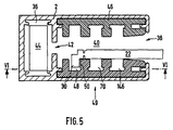
- the longer (left) guide rail 2 and the shorter (right) Guide rail 4 formed as a hollow profile and each include one based on the width of the roller shutter curtain 16 outer guide channel 36 and an inner, from the roller shutter curtain 16 through a Opening 38 accessible chamber 40, being between the outer Guide channel 36 and the inner chamber 40 in the longitudinal direction of the guide rail extending slot 42 is present.
- an additional weight 44 are longitudinally displaceable, are in the inner chamber 40 multi-groove inserts 46, preferably made of PVC, are fitted, which on the side surfaces are in the longitudinal direction of the guide rail 2 extending in the plane of the roller shutter curtain 16 seen in a line one behind the other guide grooves 49 have, the groove edges of which are encompassed by the lamella lugs 30 Represent leading edges 50 for the short lamellae 22 that can protrude through the opening 38 into the interior of the chamber 40, as can also be seen from FIG. 6.
- the lamella lugs 30 protrude vertically, for example, into an outer guide groove 48 of preferably three guide grooves 49 into the two Side surfaces of the chamber 40 are symmetrical opposite each other are distributed to use the guide rail 2 universally can, e.g. also for a roller shutter, its longer guide rail is located on the right.
- the left bearing plate 8 is by means of an articulated connection, preferably by a hinge joint 52 on the top End 54 of the longer (left) guide rail 2 adjustable inclination held, with the hinge axis of rotation 56 substantially runs horizontally and perpendicular to the winding shaft 6.
- a lower one Articulated arm 58 of the hinge joint 52 is in the outer guide channel 36 of the longer (left) guide rail 2 and the upper one Articulated arm 60 attached to the left bearing plate 8.
- the face 62 of the longer (left) guide rail 2 is corresponding to the Inclination ⁇ of the winding shaft 6 beveled, preferably by a oblique saw cut.
- the lower articulated arm 58 of the hinge joint 52 is drawn into the guide channel 36 so deeply that on the one hand the axis of rotation 56 of the hinge joint 52nd is covered and on the other hand, the left bearing plate 8 on the underside on the edges of the sloping face open towards the top 62 of the longer (left) guide rail 2 can support.
- the shorter (right) guide rail 4 is on the right bearing plate 10 also attached by means of an articulated connection, so that the Inclination of the entire roller shutter box 12 relative to the guide rails 2, 4 according to the sloping roof is adjustable.
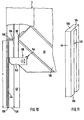
- Fig.6 shows includes the support device 64, preferably made of plastic existing, in a to the axis of rotation 56 of the hinge joint 52nd vertical cam 66.
- a pin 68 is formed on the end of the cam disk 66 the slat-guiding outer guide groove 48 as seen in the next inner, middle guide groove 70 of the guide rail 2 in Longitudinal guide groove inserted and there, for example: using a Screw is secured.
- a guide groove 72 in the cam 66 trained, which is one of the slat leading Guide groove 48 of the guide rail 2 adjoining in alignment, straight and vertical section 74 and one end essentially arcuate section forming a curve 76 having.
- the edge of the Guide groove 72 a guide edge 78 for the lamella lugs 30 of the short lamellae 22.
- the curve 76 of the guide groove 72 is preferred long trained to make a steady and smooth transition the short slats 22 from the vertical guide rail 2 to the on the other hand, to enable diagonally arranged winding shaft 6.
- a short lamella 22 is shown in FIG. which is heading towards during a winding process towards the winding shaft 6 and the lamella nose 30 moves the Around the leading edge 78 in the view shown from behind.
- the Cam 66 is completely in the upper end 54 of the longer (Left) guide rail 2 added, with its upper end 80 to a parting plane 82 arranged parallel to the winding shaft 6 between the guide strips 2, 4 and the roller shutter box 12 borders on which the bearing plates 8, 10 stand vertically. Consequently no parts protrude from the longer (left) guide rail 2 out, which when installing the roller shutter box 12 could be damaged.
- the parting plane 82 is created by the upper ends 54 of the guide rails 2, 4 accordingly the inclination ⁇ of the winding shaft 6 beveled.
- the roller shutter box 12 can then slide in the lower articulated arm 58 in the guide channel 36 simply on the corresponding bevelled upper end face 62 of the guide rail 2 placed become.
- An end section 84 of curve 76 borders perpendicularly to the parting plane 82, which is coplanar with the oblique end face 62 the longer (left) guide rail 2, one at the end portion 84 of the curve 76 essentially created tangent is parallel to the bearing plate 8.
- a curve 76 is formed at the upper end 80 thereof is one of the maximum possible inclination ⁇ of the slats 14 corresponding arc angles - e.g. 45 degrees according to Fig. 7 - having. Then you separate the unnecessary curve curve 76 by moving the upper end 80 of the cam accordingly a chosen inclination ⁇ e.g. saws off.
- the end section 84 of curve 76 preferably opens vertically into the upper end 80 of the cam 66 or in the parting plane 82, so that the left slat ends of the short slats 22 already parallel when running out of the cam 66 in one plane are aligned with the bearing plate 8.
- 7 are dashed lines as an example Separation lines 88 for angle of inclination ⁇ in the range of 5 degrees up to 45 degrees, which is based on a center point 90 of the arcuate curve 76 extend radially and along which the top end 80 of the standard cam 86 is separated.
- the curve 76 of the cam disk 66 is in a separating plane 82 with butt joint adjoining lamella guide channel 92 continued in alignment, the one on the left Bearing plate 8 is connected to the bearing block 94.
- the support device 64 is a flexible guide bar 96 included.
- a lower end of the guide bar 96 is in the longer (left) guide rail 2 attached by a molded Pin 98 in the guide groove leading from the slats 48 seen from the next inner, middle guide groove 70 of the guide rail 2 inserted in the longitudinal direction of the guide groove and there e.g. secured with a screw.
- the top end 100 of the Guide bar 96 stands by means of the attached to the bearing plate 8 Bearing block 94 in connection therewith and is essentially in the inclined parting plane 82 between the guide rail 2 and the roller shutter box 12.
- the curved guide bar 96 is preferably as long as possible a steady and smooth transition of the slats 14 from the Allow guide rail 2 on the winding shaft 6, and is in upwardly open end 54 of the guide rail 2 from the outside housed invisibly.
- the radially outer surface 102 of the curved Guide bar 96 then forms a guide edge 104 for the lamella lugs 30 as a fleeting extension of the leading edge 50 of the slat-guiding guide groove 48 of the longer (left) Guide rail 2.
- the bearing block supporting the upper end 100 of the guide bar 96 94 is preferred over the bearing plate 8 on one linear guide 106 fixable guided, for example, a from the bearing plate 8 preferably vertically protruding threaded rod 108 includes that in an internally threaded Through hole is screwed into the bracket 94.
- the threaded rod 108 By turning the threaded rod 108, the position of the Bearing blocks 94 adjustable in a direction perpendicular to the bearing plate 8.
- the straight end faces are tangent to the bearing block 94 the short lamellae 22 when they run out of the guide rail 2 aligned in a plane parallel to the bearing plate 8, such as shows the slat position X '' in Fig.6. With the pedestal 94 the winding position of the short lamellae 22 relative to the winding shaft 6 and adjustable to the bearing plate 8 in order to influence the winding behavior.
- the support device 64 also includes the in Winding direction on cam 66 or on the lamella guide bar 96 adjoining, elastic slat guide channel 92, which is radially spaced from the winding shaft 6 and is shown in solid lines in FIG undeformed initial state essentially tangential extends to the circumferential direction.
- the slat guide channel 92 is between two parallel to each other, with their Ends 109 on the guide rail side are firmly clamped in the bearing block 94 and guide channel strips protruding vertically from it 110 formed, which in the undeformed initial state lie in planes that are parallel to the winding shaft.
- the adjustable bearing block 94 also serves one Initial section 112 of the slat guide channel held by him 92 in alignment with the end section 84 of curve 76 in FIG Bring standard cam 86, the upper end according to 80 the respective slat inclination ⁇ was cut off at an angle.
- the initial section moves 112 of the slat guide channel 92 along a first Circular path around the axis of rotation 56 of the articulated connection 52 between Bearing plate 8 and guide rail 2 during the end section 84 of curve 76 at the correspondingly sawn-off end 80 the cam 66 around an imaginary second circular path the center point 90 lies, with the two circular paths in the Partition plane 82 must tangent to connect to each other there to be able to.
- This connection is then through an appropriate position setting of the bearing block 94 can be produced.
- the bearing block 94 in a direction transverse to end portion 84 of curve 76 and parallel to the parting plane 82 such that the end portion 84 of the Curve 76 with a longitudinal edge 114 forming a leading edge the guide channel strip 116 closest to the winding shaft 6 flees.
- this longitudinal edge 114 is an extension of its leading edge 104.
- the lamella lugs 30 of the short lamellae 22 are on the longitudinal edge 114 of the guide channel strip 116 by reaching around guided, as illustrated by the slat position X '' in Fig. 8 and Fig. 9 is shown, while the short lamellae 22 itself in a Level are aligned parallel to the winding shaft 6 and themselves extend through the lamella guide channel 92.
- the baffle 118 is spaced from the long sides the guide channel strips 110 arranged, the slightly is larger than the diameter of the lamella lugs 30 of the short lamellae 22, whereby this in the gap 120 formed thereby can be positively guided, as can be clearly seen in Fig. 8.
- the free end 122 of this elastic guide channel strip 116 is - analogously to one firmly clamped in a wall and beams loaded by lateral forces - accordingly the respective diameter of the armored winding towards this preferably curved in a circular arc, preferably in this way wide until the upper end of this guide channel strip 116 is almost on reaches the size of the armored winding. Because the free ends 122 of the two guide channel strips 110 by a bracket 124 are interconnected, the more distant from the winding shaft 6 Guide channel strip 126 taken along and equidistant held, which is why the lamella guide channel 92 in a plane parallel to the bearing plate 8 overall like an arc deformed.
- slat guide channel 92 responsible for the deformation of the slat guide channel 92 is on the one hand the component acting transversely to it resulting from the rotation of the winding shaft 6 Tractive forces in the roller shutter curtain 16 and the other in the same Directional component of the weight below of the slat guide channel 92 located slats 14, wherein overall there is a positive control of the elastic slat guide channel 92 by the movement of the roller shutter curtain 16 results.
- the elastic deformation creates in the guide channel strips 110 in response restoring forces that the shutter curtain 16 keep under tension, whereby the lamellar lugs 30 of the the short lamella 22 passing through the lamella guide channel 92 against the leading edge 114 of the closest to the winding shaft Guide channel bar 116 are pressed. Due to the higher contact pressure there is a jumping off of the lamella lugs 30 from the leading edge 114 avoided and thus smooth running and safe running of the roller shutter 1 increased. Since the slat guide channel 92 is held on the adjustable pedestal 94, its distance from the bearing plate 8 variable.
- the elongated additional weight 44 has one of his Bottom 128 up to its upper end 130 in the running direction of the Roller shutter 16 extending slot 132, which is upward bounded by a stop 134 designed as a crossbar is.
- slot 132 engages on a lowermost lamella 136 of the roller shutter curtain 16 fastened driver 138 and can start from a lowest position in which the lowest slat 136 rests on the lower window edge, up to one top stop position, in which the driver 138 just at Stop 134 stops, run along.
- the additional weight 44 from the roller shutter curtain 16 taken, which then almost completely in the Roller shutter box 12 can be retracted because that below the lowest slat 136 carried additional weight 44 outside of Roller shutter box 12, namely in the upper end 54 of the outer guide channel 36 of the guide rail 2 remains. Furthermore is achieved by the driver slot arrangement shown, that the additional weight 44 the loss of effective weight compensated only when necessary, i.e. if the roller shutter armor 16 partially or completely on the winding shaft 6 is wound. In contrast, the driver 138 is at closed or almost closed roller shutter 1 if that effective dead weight of the hanging slats 14 is sufficient, with the additional weight 44 out of engagement.
- the distance Y of the stop 134 from the lower edge of the window or from the floor 128 of the additional weight 44 is accordingly determined, from which Degree of closing or opening of the roller shutter 1 the additional weight 44 takes effect, the distance Y slightly to the respective Requirements can be adjusted.
- roller shutter armor 16 for closing the Window opening must be completely handled because after reaching the stop position the elongated additional weight 44 on the floor 140 of the guide channel 36 sits and the driver 138 over this stop position in the slot 132 so far down can run until the lowest slat 136 the lower edge of the window has reached.
- the driver is 138 eccentrically articulated on the lowest slat 136, whereby its longer part 142 faces the additional weight 44. Because the roller shutter 16 when installing from above into the longer (left) guide rail 2 is introduced, the driver 138 can then in twist an approximately vertical position if it hits from above hits the stop 134 of the additional weight 44. After passing the stop 134 ensures the greater weight of the longer Part 142 for that the driver 138 in the counterclockwise direction pivoted and folded into a horizontal operative position, in which he then by a schematically indicated in Fig.10 the lowest slat 136 fixed stop 144 is held.
- the lamellar lugs 30 are in the Roller shutter curtain 16 guided from the outer guide groove 48. Since the leading edge 104 of the slat guide strip 96 after points outside, its pin 98 is from the slat-guiding guide groove 48 seen from the inside, in the present case inserted in the middle guide groove 70.
- the inner guide groove 146 can then only be used to hold the pin 98 and the outer Guide groove 48 is provided only for guiding the short blades 22 be, whereas the middle guide groove 70 optionally for slat guidance or can serve as a pin holder.
- the distance the guide grooves 49 from one another is chosen such that whose leading edges 50 always with the leading edge 104 of the Slat guide strip 96 are aligned, regardless of their plug position.
- the cam 66 is also to be repositioned 6 from the middle guide groove 70 into the inner guide groove 146 possible if cam 66 is narrower than in the example is shown trained.
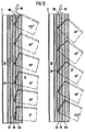
- the lamella 30 depending on the inclination in a certain guide groove 49 of the longer (left) guide rail 2 engages, the representation along a section corresponds to the line VI - VI of Fig.5. Accordingly, the lamellar lugs 30 for example in the area of low inclination, e.g. between 1 degree and 27.5 degrees, held in the middle guide groove 70 and the pin 98 of the guide bar 96 is in the inner guide groove 146 inserted, as shown in the left half of Fig.10 is.
- the lamella lugs 30 are in the outer guide groove 48 held and the pin 98 of the guide bar 96 is held by the central guide groove 70 when the inclination ⁇ of Slats 14 according to the right half of Figure 8 is larger and for example is between 27.6 degrees and 45 degrees.
- 49 is not based on the three of the exemplary embodiment limited, depending on the requirements can also be more or less Guide grooves 49 may be provided.
- roller shutter according to the invention has the following Features on:
- the support device 64 includes a flexible, preferably Slat guide strip 96 made of plastic includes one end 98 in the area of the upper end 54 the slat guide rail 2 is attached and the other End 100 is connected to the bearing plate 8, the slat guide bar 96 between their two ends 98, 100 depending bendable in this way by the respective inclination ⁇ of the winding shaft 6 is that a gradual, preferably circular arc Transition from the guide rail 2 into a plane parallel to the bearing plate 8 is created.
- the slat guide bar 2 is in one to the pivot axis 56 of the articulation 52 vertical plane, being their radially outer surface 10 a leading edge 104 for the slats 22 forms.
- the slats 22 are preferably on the guide rail 2 closest corner with a perpendicular to the slat plane extending, the leading edge 104 of the slat guide bar 96 encompassing lamella nose 30 provided by which the slats 22 on the slat guide bar 96 form-fitting are held.
- the support device 64 further comprises a bearing block 94, at which the other end 100 of the flexible slat guide strip 96 is fixed parallel to the bearing plate 8 and which one along a preferably linear attached to the bearing plate 8 Guide 106 is guided fixable.
- the support device 64 also includes a winding direction to the slat guide strip 96 adjoining, flexible Lamella guide channel 92, which from the winding shaft 6 is radially spaced and due to the weight and Movement of the roller shutter curtain 16 in a parallel to the bearing plate 8 level in the direction of the winding shaft 6 bendable in such a way is that due to its elastic deformation Restoring forces keep the roller shutter curtain 16 under tension.
- the lamella guide channel 92 is parallel to one another between two extending, firmly clamped in the bearing block 94
- Guide strips 110 formed, the free ends 122 by a Brackets 124 are interconnected and have a longitudinal edge 114 one of the guide strips 116 the leading edge for the lamella lugs 30 forms.
- the lamella lugs 30 are dependent on the inclination .alpha Winding shaft 6 optionally in one of several, in one the roller shutter curtain 16 containing plane arranged equidistantly one behind the other, extending in the longitudinal direction of the slat guide rail 2 and guide grooves 50 forming guide edges at the groove edge 48, 70, 146 feasible in the longitudinal direction of the guide groove, and in such a way that when the angle of inclination ⁇ increases, the lamella noses 30 in a further seen from the roller shutter curtain 16 outside guide groove 48 are guided.
- One at one end of the flexible slat guide strip 96 trained pin 98 is in a with respect to slat-guiding guide groove 48 next inner guide groove 70 insertable and the distance of the guide grooves 48, 70, 146 from each other is so large that the guide edges 50 of the guide grooves 48, 70, 146 regardless of the plug position of the pin 98 with of the guide edge 104 of the slat guide strip 96 are aligned.
- the lower end 136 of the roller shutter curtain 16 stands with one Additional weight in combination, which is preferably in an inside the guide rail 2 formed guide channel 36 is longitudinally displaceable is led.
- the support device 64 can also be one with one gradual transition from the guide rail to one level parallel to the bearing plate, preferably circular Include lamella guideway provided with curve 76, with a first guideway section carried by the guide rail 2 66 and one in the winding direction of the roller shutter curtain 16 adjoining this, carried by the bearing plate 8 and at least at the end parallel to this second one Guideway section 92, the first guideway section 66 relative to the guide rail 2 and / or the second guide section 92 is adjustable relative to the bearing plate 8 such that a Outlet 84 of the first guideway section 76 with an inlet 112 of the second guideway section 92 is aligned.
- the outlet 84 of the first guideway section 66 borders to a slope corresponding to the inclination ⁇ of the winding shaft 6 Parting plane 82 between the guide rail 2 and the bearing plate 8 and the position of at least the inlet 112 of the second guideway section 92 is in a direction parallel to the parting plane 82 adjustable.
- the first guideway section preferably includes one made of plastic, in a to the pivot axis 56 of the Articulated connection 52 vertical plane and inside the guide rail 2 received cam 66, with the Curve 76 which is perpendicular to a corresponding to the inclination ⁇ of the winding shaft 6 chamfered upper end 80 of the cam disk 76 flows.
- the second guideway section includes a parallel to the Bearing plate 8 arranged lamella guide channel 92, which is preferably can be fixed in a direction perpendicular to the bearing plate is guided, the lamella guide channel 92 between two parallel to each other, firmly clamped in the bearing block 94 Guide strips 110 is formed, the free ends 122 are connected by a bracket 124.
- the sliding bodies 30 are dependent on the angle of inclination ⁇ the winding shaft 6 optionally in one of several, in one Roller shutter armor 16 containing plane preferably equidistant arranged one behind the other, in the longitudinal direction of the slat guide rail 2 extending and at the groove edge guide edges 50 forming guide grooves 48, 70, 146 feasible such that when the inclination angle ⁇ increases, the sliding bodies 30 in a further outward as seen from the roller shutter curtain 16 Guide groove 48 are performed.
Landscapes
- Engineering & Computer Science (AREA)
- Structural Engineering (AREA)
- Architecture (AREA)
- Civil Engineering (AREA)
- Operating, Guiding And Securing Of Roll- Type Closing Members (AREA)
- Specific Sealing Or Ventilating Devices For Doors And Windows (AREA)
- Finishing Walls (AREA)
Applications Claiming Priority (8)
| Application Number | Priority Date | Filing Date | Title |
|---|---|---|---|
| DE1999145905 DE19945905C1 (de) | 1999-09-24 | 1999-09-24 | Rolladen für von der Rechteckform abweichende Formen von Gebäudeöffnungen |
| DE19945906 | 1999-09-24 | ||
| DE19945905 | 1999-09-24 | ||
| DE1999145908 DE19945908C2 (de) | 1999-09-24 | 1999-09-24 | Rolladen für von der Rechteckform abweichende Formen von Gebäudeöffnungen |
| DE19945906 | 1999-09-24 | ||
| DE19945908 | 1999-09-24 | ||
| DE20005831U | 2000-03-29 | ||
| DE20005831U DE20005831U1 (de) | 1999-09-24 | 2000-03-29 | Rolladen für von der Rechteckform abweichende Formen von Gebäudeöffnungen |
Publications (3)
| Publication Number | Publication Date |
|---|---|
| EP1087094A2 true EP1087094A2 (fr) | 2001-03-28 |
| EP1087094A3 EP1087094A3 (fr) | 2003-02-05 |
| EP1087094B1 EP1087094B1 (fr) | 2009-06-10 |
Family
ID=27438987
Family Applications (2)
| Application Number | Title | Priority Date | Filing Date |
|---|---|---|---|
| EP00119417A Expired - Lifetime EP1087094B1 (fr) | 1999-09-24 | 2000-09-13 | Volet roulant pour ouvertures de bâtiments, et dont la forme diffère de la forme rectangulaire |
| EP00119416A Expired - Lifetime EP1087093B1 (fr) | 1999-09-24 | 2000-09-13 | Volet roulant pour ouvertures de bâtiments, et dont la forme diffère de la forme rectangulaire |
Family Applications After (1)
| Application Number | Title | Priority Date | Filing Date |
|---|---|---|---|
| EP00119416A Expired - Lifetime EP1087093B1 (fr) | 1999-09-24 | 2000-09-13 | Volet roulant pour ouvertures de bâtiments, et dont la forme diffère de la forme rectangulaire |
Country Status (3)
| Country | Link |
|---|---|
| EP (2) | EP1087094B1 (fr) |
| AT (1) | ATE309445T1 (fr) |
| DE (1) | DE50011552D1 (fr) |
Cited By (1)
| Publication number | Priority date | Publication date | Assignee | Title |
|---|---|---|---|---|
| WO2013128160A1 (fr) * | 2012-02-29 | 2013-09-06 | Ideas By Design Ltd | Agencement pour monter un rail guide de moustiquaire |
Citations (1)
| Publication number | Priority date | Publication date | Assignee | Title |
|---|---|---|---|---|
| DE3725380C2 (fr) | 1987-07-31 | 1990-03-29 | Reflexa-Werke H.P. Albrecht Gmbh & Co Kg, 8871 Rettenbach, De |
Family Cites Families (3)
| Publication number | Priority date | Publication date | Assignee | Title |
|---|---|---|---|---|
| DE2707467C2 (de) * | 1977-02-21 | 1987-01-08 | Kurt 7336 Uhingen Jüngling | Rolladen für Fenster und Türen mit schräg verlaufendem oberem Rahmenteil |
| DE3806893C2 (de) * | 1988-03-03 | 1996-06-20 | Reflexa Werke H P Albrecht | Rolladen |
| DE19547587C2 (de) * | 1995-12-20 | 2000-11-16 | Guenter Degendorfer | Rolladen für asymmetrische Öffnungen |
-
2000
- 2000-09-13 EP EP00119417A patent/EP1087094B1/fr not_active Expired - Lifetime
- 2000-09-13 AT AT00119416T patent/ATE309445T1/de not_active IP Right Cessation
- 2000-09-13 EP EP00119416A patent/EP1087093B1/fr not_active Expired - Lifetime
- 2000-09-13 DE DE50011552T patent/DE50011552D1/de not_active Expired - Lifetime
Patent Citations (1)
| Publication number | Priority date | Publication date | Assignee | Title |
|---|---|---|---|---|
| DE3725380C2 (fr) | 1987-07-31 | 1990-03-29 | Reflexa-Werke H.P. Albrecht Gmbh & Co Kg, 8871 Rettenbach, De |
Cited By (4)
| Publication number | Priority date | Publication date | Assignee | Title |
|---|---|---|---|---|
| WO2013128160A1 (fr) * | 2012-02-29 | 2013-09-06 | Ideas By Design Ltd | Agencement pour monter un rail guide de moustiquaire |
| US9512673B2 (en) | 2012-02-29 | 2016-12-06 | Ideas By Design Ltd. | Apparatus for mounting a screen guide rail |
| AU2013206333B2 (en) * | 2012-02-29 | 2017-04-20 | Ideas By Design Ltd | Apparatus for mounting a screen guide rail |
| GB2502039B (en) * | 2012-02-29 | 2017-11-15 | Ideas By Design Ltd | Apparatus for mounting a screen guide rail |
Also Published As
| Publication number | Publication date |
|---|---|
| EP1087093B1 (fr) | 2005-11-09 |
| EP1087093A2 (fr) | 2001-03-28 |
| EP1087094B1 (fr) | 2009-06-10 |
| EP1087094A3 (fr) | 2003-02-05 |
| ATE309445T1 (de) | 2005-11-15 |
| DE50011552D1 (de) | 2005-12-15 |
| EP1087093A3 (fr) | 2003-01-29 |
Similar Documents
| Publication | Publication Date | Title |
|---|---|---|
| EP0230999B1 (fr) | Porte roulante verticale pour basses hauteurs de linteau | |
| DE2317086B2 (de) | Tür o.dgl. aus mehreren teleskopartig verschiebbaren Elementen | |
| EP0653012B1 (fr) | Volet roulant du type jalousie | |
| EP1639224A2 (fr) | Porte sectionnelle | |
| DE19964285C2 (de) | Rolladen für von der Rechteckform abweichende Formen von Gebäudeöffnungen | |
| DE102009021473B3 (de) | Beschattungsvorrichtung und Führungselement dafür | |
| DE69506325T2 (de) | Verschlusseinrichtung | |
| EP1087094B1 (fr) | Volet roulant pour ouvertures de bâtiments, et dont la forme diffère de la forme rectangulaire | |
| DE102016113086B4 (de) | Wasserdichte Sektionaltor-Vorrichtung | |
| DE19835684A1 (de) | Verfahrbare Türflügelanordnung | |
| CH696275A5 (de) | Raffstore mit Wendelager. | |
| CH694436A5 (de) | Rolladen. | |
| DE19945905C1 (de) | Rolladen für von der Rechteckform abweichende Formen von Gebäudeöffnungen | |
| DE4406875C2 (de) | Rolladen für eine trapezförmige Gebäudeöffnung | |
| WO1984004129A1 (fr) | Store a lamelles | |
| DE1784507A1 (de) | In der Kopfschiene einer Jalousic anbringbare Halterung fuer die Rolle von Jalousiebaendern | |
| EP0267303B1 (fr) | Partie de pied pour un dispositif de guidage latéral | |
| DE2328822A1 (de) | Lamellenfuehrung fuer jalousie-lamellen | |
| WO2004029396A1 (fr) | Porte a coulissement rapide | |
| DE3735968A1 (de) | Schiebetor | |
| DE10339160A1 (de) | Lamellenfenster | |
| DE202004004863U1 (de) | Rolladen für von der Rechteckform abweichende Formen von Gebäudeöffnungen | |
| DE7012310U (de) | Rolltor. | |
| DE102019103662A1 (de) | Verbundraffstore über Eck | |
| DE29902981U1 (de) | Rolladen-Kasten, insbesondere Rolladen-Aufsatzkasten |
Legal Events
| Date | Code | Title | Description |
|---|---|---|---|
| PUAI | Public reference made under article 153(3) epc to a published international application that has entered the european phase |
Free format text: ORIGINAL CODE: 0009012 |
|
| 17P | Request for examination filed |
Effective date: 20000913 |
|
| AK | Designated contracting states |
Kind code of ref document: A2 Designated state(s): AT BE CH CY DE DK ES FI FR GB GR IE IT LI LU MC NL PT SE |
|
| AX | Request for extension of the european patent |
Free format text: AL;LT;LV;MK;RO;SI |
|
| PUAL | Search report despatched |
Free format text: ORIGINAL CODE: 0009013 |
|
| AK | Designated contracting states |
Designated state(s): AT BE CH CY DE DK ES FI FR GB GR IE IT LI LU MC NL PT SE |
|
| AX | Request for extension of the european patent |
Extension state: AL LT LV MK RO SI |
|
| RIC1 | Information provided on ipc code assigned before grant |
Ipc: 7E 06B 9/58 A Ipc: 7E 06B 9/15 B |
|
| AKX | Designation fees paid |
Designated state(s): AT BE CH DE FR LI NL |
|
| 17Q | First examination report despatched |
Effective date: 20070515 |
|
| GRAP | Despatch of communication of intention to grant a patent |
Free format text: ORIGINAL CODE: EPIDOSNIGR1 |
|
| GRAS | Grant fee paid |
Free format text: ORIGINAL CODE: EPIDOSNIGR3 |
|
| GRAA | (expected) grant |
Free format text: ORIGINAL CODE: 0009210 |
|
| AK | Designated contracting states |
Kind code of ref document: B1 Designated state(s): AT BE CH DE FR LI NL |
|
| REG | Reference to a national code |
Ref country code: CH Ref legal event code: EP |
|
| REF | Corresponds to: |
Ref document number: 50015657 Country of ref document: DE Date of ref document: 20090723 Kind code of ref document: P |
|
| REG | Reference to a national code |
Ref country code: CH Ref legal event code: NV Representative=s name: ISLER & PEDRAZZINI AG |
|
| NLV1 | Nl: lapsed or annulled due to failure to fulfill the requirements of art. 29p and 29m of the patents act | ||
| PG25 | Lapsed in a contracting state [announced via postgrant information from national office to epo] |
Ref country code: NL Free format text: LAPSE BECAUSE OF FAILURE TO SUBMIT A TRANSLATION OF THE DESCRIPTION OR TO PAY THE FEE WITHIN THE PRESCRIBED TIME-LIMIT Effective date: 20090610 |
|
| BERE | Be: lapsed |
Owner name: ROMA ROLLADENSYSTEME G.M.B.H. Effective date: 20090930 |
|
| PLBE | No opposition filed within time limit |
Free format text: ORIGINAL CODE: 0009261 |
|
| STAA | Information on the status of an ep patent application or granted ep patent |
Free format text: STATUS: NO OPPOSITION FILED WITHIN TIME LIMIT |
|
| 26N | No opposition filed |
Effective date: 20100311 |
|
| PG25 | Lapsed in a contracting state [announced via postgrant information from national office to epo] |
Ref country code: BE Free format text: LAPSE BECAUSE OF NON-PAYMENT OF DUE FEES Effective date: 20090930 |
|
| PGFP | Annual fee paid to national office [announced via postgrant information from national office to epo] |
Ref country code: CH Payment date: 20110926 Year of fee payment: 12 |
|
| REG | Reference to a national code |
Ref country code: CH Ref legal event code: PFA Owner name: ROMA KG Free format text: ROMA ROLLADENSYSTEME GMBH#OSTPREUSSENSTRASSE 9#89331 BURGAU (DE) -TRANSFER TO- ROMA KG#OSTPREUSSENSTRASSE 9,#89331 BURGAU (DE) |
|
| REG | Reference to a national code |
Ref country code: FR Ref legal event code: CD Owner name: ROMA KG, DE Effective date: 20120111 |
|
| REG | Reference to a national code |
Ref country code: DE Ref legal event code: R082 Ref document number: 50015657 Country of ref document: DE Representative=s name: MARKUS WIEDEMANN, DE |
|
| REG | Reference to a national code |
Ref country code: DE Ref legal event code: R082 Ref document number: 50015657 Country of ref document: DE Representative=s name: MARKUS WIEDEMANN, DE |
|
| REG | Reference to a national code |
Ref country code: DE Ref legal event code: R082 Ref document number: 50015657 Country of ref document: DE Representative=s name: WIEDEMANN, MARKUS, DIPL.-ING.UNIV. DR.-ING., DE Effective date: 20120410 Ref country code: DE Ref legal event code: R081 Ref document number: 50015657 Country of ref document: DE Owner name: ROMA KG, DE Free format text: FORMER OWNER: ROMA ROLLADENSYSTEME GMBH, 89331 BURGAU, DE Effective date: 20120410 Ref country code: DE Ref legal event code: R082 Ref document number: 50015657 Country of ref document: DE Representative=s name: WIEDEMANN, MARKUS, DIPL.-ING.UNIV. DR.-ING., DE Effective date: 20120220 |
|
| REG | Reference to a national code |
Ref country code: AT Ref legal event code: HC Ref document number: 433533 Country of ref document: AT Kind code of ref document: T Owner name: ROMA KG, DE Effective date: 20120427 |
|
| PGFP | Annual fee paid to national office [announced via postgrant information from national office to epo] |
Ref country code: FR Payment date: 20121008 Year of fee payment: 13 |
|
| PGFP | Annual fee paid to national office [announced via postgrant information from national office to epo] |
Ref country code: AT Payment date: 20120919 Year of fee payment: 13 |
|
| REG | Reference to a national code |
Ref country code: CH Ref legal event code: PL |
|
| REG | Reference to a national code |
Ref country code: AT Ref legal event code: MM01 Ref document number: 433533 Country of ref document: AT Kind code of ref document: T Effective date: 20130913 |
|
| REG | Reference to a national code |
Ref country code: FR Ref legal event code: ST Effective date: 20140530 |
|
| PG25 | Lapsed in a contracting state [announced via postgrant information from national office to epo] |
Ref country code: LI Free format text: LAPSE BECAUSE OF NON-PAYMENT OF DUE FEES Effective date: 20130930 Ref country code: CH Free format text: LAPSE BECAUSE OF NON-PAYMENT OF DUE FEES Effective date: 20130930 |
|
| PG25 | Lapsed in a contracting state [announced via postgrant information from national office to epo] |
Ref country code: FR Free format text: LAPSE BECAUSE OF NON-PAYMENT OF DUE FEES Effective date: 20130930 Ref country code: AT Free format text: LAPSE BECAUSE OF NON-PAYMENT OF DUE FEES Effective date: 20130913 |
|
| PGFP | Annual fee paid to national office [announced via postgrant information from national office to epo] |
Ref country code: DE Payment date: 20160819 Year of fee payment: 17 |
|
| REG | Reference to a national code |
Ref country code: DE Ref legal event code: R119 Ref document number: 50015657 Country of ref document: DE |
|
| PG25 | Lapsed in a contracting state [announced via postgrant information from national office to epo] |
Ref country code: DE Free format text: LAPSE BECAUSE OF NON-PAYMENT OF DUE FEES Effective date: 20180404 |