EP1087111B1 - Procédé de fabrication d'une came tridimensionelle - Google Patents
Procédé de fabrication d'une came tridimensionelle Download PDFInfo
- Publication number
- EP1087111B1 EP1087111B1 EP00120543A EP00120543A EP1087111B1 EP 1087111 B1 EP1087111 B1 EP 1087111B1 EP 00120543 A EP00120543 A EP 00120543A EP 00120543 A EP00120543 A EP 00120543A EP 1087111 B1 EP1087111 B1 EP 1087111B1
- Authority
- EP
- European Patent Office
- Prior art keywords
- cam
- dimensional
- sintering
- dimensional cam
- shape
- Prior art date
- Legal status (The legal status is an assumption and is not a legal conclusion. Google has not performed a legal analysis and makes no representation as to the accuracy of the status listed.)
- Expired - Lifetime
Links
- 238000004519 manufacturing process Methods 0.000 title claims description 26
- 238000005245 sintering Methods 0.000 claims description 42
- 239000000463 material Substances 0.000 claims description 20
- 239000000843 powder Substances 0.000 claims description 9
- 238000000465 moulding Methods 0.000 claims description 6
- 150000001875 compounds Chemical class 0.000 claims description 2
- 238000000034 method Methods 0.000 description 13
- 230000008569 process Effects 0.000 description 11
- 230000008901 benefit Effects 0.000 description 6
- 238000002485 combustion reaction Methods 0.000 description 6
- 230000007423 decrease Effects 0.000 description 6
- 210000001331 nose Anatomy 0.000 description 5
- 238000005299 abrasion Methods 0.000 description 4
- 239000000314 lubricant Substances 0.000 description 4
- 238000000227 grinding Methods 0.000 description 3
- 230000006872 improvement Effects 0.000 description 3
- XEEYBQQBJWHFJM-UHFFFAOYSA-N Iron Chemical compound [Fe] XEEYBQQBJWHFJM-UHFFFAOYSA-N 0.000 description 2
- 238000010276 construction Methods 0.000 description 2
- 238000003754 machining Methods 0.000 description 2
- 230000014759 maintenance of location Effects 0.000 description 2
- 239000002245 particle Substances 0.000 description 2
- 238000004663 powder metallurgy Methods 0.000 description 2
- 230000015572 biosynthetic process Effects 0.000 description 1
- 230000008859 change Effects 0.000 description 1
- 238000010273 cold forging Methods 0.000 description 1
- 238000005056 compaction Methods 0.000 description 1
- 238000001816 cooling Methods 0.000 description 1
- 230000001419 dependent effect Effects 0.000 description 1
- 238000011161 development Methods 0.000 description 1
- 230000018109 developmental process Effects 0.000 description 1
- 238000010586 diagram Methods 0.000 description 1
- 239000007791 liquid phase Substances 0.000 description 1
- 230000007246 mechanism Effects 0.000 description 1
- 239000000203 mixture Substances 0.000 description 1
- 238000012986 modification Methods 0.000 description 1
- 230000004048 modification Effects 0.000 description 1
- 239000011800 void material Substances 0.000 description 1
Images

Classifications
-
- F—MECHANICAL ENGINEERING; LIGHTING; HEATING; WEAPONS; BLASTING
- F01—MACHINES OR ENGINES IN GENERAL; ENGINE PLANTS IN GENERAL; STEAM ENGINES
- F01L—CYCLICALLY OPERATING VALVES FOR MACHINES OR ENGINES
- F01L13/00—Modifications of valve-gear to facilitate reversing, braking, starting, changing compression ratio, or other specific operations
- F01L13/0015—Modifications of valve-gear to facilitate reversing, braking, starting, changing compression ratio, or other specific operations for optimising engine performances by modifying valve lift according to various working parameters, e.g. rotational speed, load, torque
- F01L13/0036—Modifications of valve-gear to facilitate reversing, braking, starting, changing compression ratio, or other specific operations for optimising engine performances by modifying valve lift according to various working parameters, e.g. rotational speed, load, torque the valves being driven by two or more cams with different shape, size or timing or a single cam profiled in axial and radial direction
- F01L13/0042—Modifications of valve-gear to facilitate reversing, braking, starting, changing compression ratio, or other specific operations for optimising engine performances by modifying valve lift according to various working parameters, e.g. rotational speed, load, torque the valves being driven by two or more cams with different shape, size or timing or a single cam profiled in axial and radial direction with cams being profiled in axial and radial direction
-
- F—MECHANICAL ENGINEERING; LIGHTING; HEATING; WEAPONS; BLASTING
- F01—MACHINES OR ENGINES IN GENERAL; ENGINE PLANTS IN GENERAL; STEAM ENGINES
- F01L—CYCLICALLY OPERATING VALVES FOR MACHINES OR ENGINES
- F01L1/00—Valve-gear or valve arrangements, e.g. lift-valve gear
- F01L1/02—Valve drive
- F01L1/04—Valve drive by means of cams, camshafts, cam discs, eccentrics or the like
- F01L1/047—Camshafts
-
- F—MECHANICAL ENGINEERING; LIGHTING; HEATING; WEAPONS; BLASTING
- F01—MACHINES OR ENGINES IN GENERAL; ENGINE PLANTS IN GENERAL; STEAM ENGINES
- F01L—CYCLICALLY OPERATING VALVES FOR MACHINES OR ENGINES
- F01L1/00—Valve-gear or valve arrangements, e.g. lift-valve gear
- F01L1/02—Valve drive
- F01L1/04—Valve drive by means of cams, camshafts, cam discs, eccentrics or the like
- F01L1/08—Shape of cams
Definitions
- the invention relates to a production method for a three-dimensional cam having a profile shape that varies along a rotating axis thereof.
- variable valve apparatus employ, as cams for opening and closing engine valves, three-dimensional cams having cam profile shapes that continuously vary along a three-dimensional cam in a direction of the rotating axis thereof by hydraulic pressure or the like, the apparatus changes the cam profile shape in contact with a valve lifter of the engine valve. In accordance with changes of contact cam profile, changes occur in the open/close timing, the open/close amount, the open/close duration, etc., of the intake or exhaust valve driven by the valve lifter.
- cam profile shape of a three-dimensional cam varies along the rotating axis
- high-precision processing of the cam profile surface of the cam is very difficult.
- a cam profile surface is machined by grinding with a grindstone as described in JP 10-44014 A, complicate process steps and an increased process time are needed in order to secure a sufficient precision.
- a three-dimensional cam is formed through integral molding by a powder metallurgy (i.e., net-shape-sintering).
- the net-shape-sintering allows highly efficient production of three-dimensional cams having complicated cam profile shapes while securing sufficient precision.
- cams used for opening and closing engine valves of internal combustion engines are required to have high durability against damage, such as slide abrasion, pitting and like, because these cams are rotated at high speeds while being pressed against valve lifters by valve springs of the engine valves and therefore receive high surface pressures.
- three-dimensional cams used in a continuously variable valve apparatus need to have further high durability because the cams also are moved in the direction of the rotating axis during operation of the internal combustion engine.
- cams formed by the aforementioned net-shape-sintering process have higher durability than normally employed cast cams, a further improvement in durability is desired because operation of cams in even more severe conditions is demanded in order to improve the performance of internal combustion engines.
- the invention has been accomplished in view of the aforementioned circumstances. It is an object of the invention to provide a production method for a three-dimensional cam having a cam profile that varies along (i.e., in the direction of) its rotating axis, the production method allowing a further improvement in durability while securing high productivity.
- Net-shape-sintering that is, integral formation by powder metallurgy, is able to form a three-dimensional cam having a complicated cam profile with a high form precision, without necessitating a machining process, and therefore is able to secure a high productivity. Since the three-dimensional cam is produced by net-shape-sintering, the production method of the invention is able to improve productivity while securing sufficient precision of the three-dimensional cam.
- a sintering material for the net-shape-sintering is compacted so that the density of the sintering material, that is, the sintered density, becomes 7 to 7.4 grams per cubic centimeter. If the net-shape-sintering is performed at a sintered density as mentioned above, the hole rate of a surface of the three-dimensional cam can be set to 5 to 10%.
- the term "hole rate" as used herein is the proportion of the total hole area to the surface area of the cam profile surface expressed in percentage.
- the presence of holes contributes to an improvement in lubricant retention because a lubricant, such as an oil or the like, enters the holes. Therefore, an increase in the hole rate further reduces the friction on the cam profile surface, that is, further improves the friction characteristic of the cam, so that slide abrasion can be more effectively curbed.
- An increase in the hole rate also increases the roughness of the cam profile surface, so that the resistance to pitting decreases.
- the present inventors have ascertained that if the hole rate is within the range of 5 to 10%, a sufficient pitting resistance can be attained while the friction is curbed within a permissible magnitude (see FIGURE 2). Therefore, according to the invention, it is possible to achieve a further improved durability in the three-dimensional cam having a cam profile that changes along the rotating axis, while securing a high productivity.
- the mold withdrawal direction is set to such a direction that the frame mold and the cam profile surface do not slidingly contact each other.
- the three-dimensional cam is removed from the frame mold by withdrawing the frame mold in such a direction that the frame mold and the cam profile surface do not slidingly contact each other, a desired hole rate can always be achieved and, therefore, a high-durability three-dimensional cam can be produced with an even higher quality.
- a frame mold having a molding surface for molding a shape of the three-dimensional cam is filled with a material powder of the three-dimensional cam.
- the material powder is press-molded by the frame mold into the shape of the three-dimensional cam at a density of about 7 to 7.4 grams per cubic centimeter.
- the molded body is sintered at a predetermined temperature. If the three-dimensional cam is produced by the above-described production method, the hole rate of the surface of the three-dimensional cam can be set to 5 to 10%.
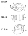
- FIGURE 1A illustrates a planar structure of a three-dimensional cam produced by one embodiment of the production method of the invention.
- FIGURE 1B illustrates a sectional view of the cam taken along line 1B-1B in FIGURE 1A.
- FIGURE 1C illustrates a perspective view of the cam.
- the three-dimensional cam 10 has a cam profile shape that varies along (i.e., in the direction of) a rotating axis A thereof. That is, the profile of the cam at the bottom of FIGURE 1B is different from the profile at the top of FIGURE 1B.
- the diameter of a base circle 12 is consistent, and the height of a cam nose 11 changes along the rotating axis A.
- the three-dimensional cam 10 is produced by net-shape-sintering. More specifically, the three-dimensional cam 10 is produced by compacting a powder-form sintering material in a frame mold, and thereby forming it into a shape as indicated above, and sintering it. If such a net-shape-sintering process is employed to produce a cam, a sufficiently high processing precision can be secured without a need to perform a machining process, such as grinding or the like. Therefore, the net-shape-sintering increases the productivity even if the product is the three-dimensional cam 10 as described above.
- a sintering material of the three-dimensional cam 10 As a sintering material of the three-dimensional cam 10, a sintering material that is excellent in abrasion resistance, for example, a compound material containing 0.6% of Mo, 0.2% of Mn, and 0.8% of C relative to a main material Fe, preferably is used.
- holes are formed in gaps between powder particles of the sintering material.
- the particle size of the sintering material is about 0.1 mm
- holes of several micrometers to 50 micrometers are formed in surfaces of the three-dimensional cam 10.
- the amount of holes can be adjusted based on the degree of compaction of the sintering material during the net-shape-sintering process. That is, if the sintering material is compacted at an increased pressure and therefore the density (sintered density) is increased, the amount of holes decreases. If the sintered density is reduced, the amount of holes increases.
- the abrasion resistance characteristic of the three-dimensional cam 10 is improved by suitably adjusting the hole rate of a cam profile surface 10a (percentage of the total area of holes to the surface area).
- FIGURE 2 indicates relationships of the hole rate of the cam profile surface 10a with the friction and the pitting on the cam profile surface occurring during operation of the three-dimensional cam 10.
- the friction on the cam profile surface 10a decreases with increases in the hole rate.
- lubricant such as an oil or the like
- an increased hole rate improves lubricant retention of the cam profile surface 10a.
- the cam profile surface 10a becomes rougher, so that pitting more readily occurs. Therefore, the allowable stress of the cam profile surface 10a with respect to pitting decreases with increases in the hole rate.
- an increase in the hole rate improves the friction performance of the three-dimensional cam 10, but reduces the pitting resistance. For example, if the hole rate is increased from 0% to 5%, the friction on the cam profile surface 10a decreases by about 10%. However, if the hole rate is increased from 10% to 13%, the allowable stress with respect to pitting falls by about 30%.
- the hole rate of the cam profile surface 10a within the range of 5 to 10%.
- cams are required to have a particularly good friction characteristic because the cams slidingly contact valve lifters.
- the range of hole rate of 5% to 10% sufficiently satisfies such a severe friction characteristic requirement and, at the same time, secures a needed pitting resistance characteristic.
- the three-dimensional cam 10 of this embodiment is produced so that the hole rate of the cam profile surface 10a is within the range of 5 to 10%.
- the hole rate of the cam profile surface 10a can be set within the range of 5 to 10% by, for example, setting the sintered density of a sintering material during the net-shape-sintering process within the range of 7 to 7.4 grams per cubic centimeter. For example, the hole rate is achieved to approximately 10 % when the sintered density is set to 7 grams per cubic centimeter. The hole rate is achieved to approximately 5 % when the sintered density is set to 7.4 grams per cubic centimeter.
- a direction of withdrawing a frame mold from the three-dimensional cam 10 is set such that the frame mold and the cam profile surface 10a do not slidingly contact each other.
- a three-dimensional cam 10 is formed by two frame molds 20A, 20B as shown in FIGURE 3, the frame mold 20A is withdrawn in a direction within a range indicated by arrows in FIGURE 3, so that the frame mold 20A can be withdrawn without rubbing against the cam profile surface 10a.
- the three-dimensional cam and the production method for the cam of this embodiment achieve the following advantages:
- the three-dimensional cam and the production method for the cam of the embodiment described above may be modified as follows.
- the mold withdrawal direction at the time of net-shape-sintering is set to such a direction that the cam profile surface 10a and the frame mold 20A do not slidingly contact each other, as in an example shown in FIGURE 3.
- the mold withdrawal direction is not limited to the direction exemplified in FIGURE 3. If in accordance with the structure of frame molds used or the structure of a three-dimensional cam 10, an appropriate mold withdrawal direction is selected such that the frame molds do not rub against the cam profile surface, an advantage similar to the advantage (3) can be achieved.
- this exemplary three-dimensional cam structure does not limit the invention.
- the construction and the production method of the invention are applicable to any three-dimensional cam as long as the cam is a three-dimensional cam having a cam profile that changes along its rotating axis, for example: a three-dimensional cam wherein the height of the cam nose is consistent and the base circle diameter varies along the rotating axis; a three-dimensional cam wherein two cam noses for main lift and sub-lift are provided and the height of at least one of the cam noses varies, and the like.
Landscapes
- Engineering & Computer Science (AREA)
- Mechanical Engineering (AREA)
- General Engineering & Computer Science (AREA)
- Gears, Cams (AREA)
- Valve-Gear Or Valve Arrangements (AREA)
- Valve Device For Special Equipments (AREA)
Claims (5)
- Procédé de production d'une came tridimensionnelle ayant une forme de profil de came qui varie le long d'un axe de rotation (A) de la came (10), caractérisé par les étapes consistant à
fritter à cotes finies une poudre de matériau de la came tridimensionnelle à une densité à l'état fritté de 7 grammes par centimètre cube à 7,4 grammes par centimètre cube afin de produire la came tridimensionnelle (10) ;
après le frittage à cotes finies, extraire la came tridimensionnelle (10) d'un moule (20A) dans une direction telle à éviter le contact par glissement entre le moule (20A) et une surface du profil de came (10a) de la came (10). - Procédé de production d'une came tridimensionnelle selon la revendication 1, dans lequel l'étape de frittage à cotes finies comprend les étapes consistant à :emplir un moule (20A) ayant une surface de moulage pour mouler une forme de la came tridimensionnelle (10), avec une poudre de matériau de la came tridimensionnelle (10) ;former un objet moulé en moulant par pression la poudre de matériau en la forme de la came tridimensionnelle à une densité de 7 grammes par centimètre cube à 7,4 grammes par centimètre cube avec le moule (20A) ; etfritter l'objet moulé.
- Procédé de production d'une came tridimensionnelle selon la revendication 2, dans lequel après l'étape d'extraction, la came (10) a une surface de profil de came (10a) ayant des trous à une proportion de 5 % à 10 % par rapport à l'aire totale de la surface de profil de came (10a).
- Procédé de production d'une came tridimensionnelle selon la revendication 1, dans lequel après l'étape de frittage à cotes finies, la came (10) a une surface de profil de came (10a) ayant des trous à une proportion de 5 % à 10 % par rapport à l'aire totale de la surface de profil de came (10a).
- Procédé de production d'une came tridimensionnelle selon une revendication quelconque, dans lequel la poudre de matériau est un matériau composite contenant 0,6 % de Mo, 0,2 % de Mn et 0,8 % de C par rapport à un matériau majeur Fe.
Applications Claiming Priority (2)
| Application Number | Priority Date | Filing Date | Title |
|---|---|---|---|
| JP26703199A JP2001090808A (ja) | 1999-09-21 | 1999-09-21 | 3次元カム及びその製造方法 |
| JP26703199 | 1999-09-21 |
Publications (3)
| Publication Number | Publication Date |
|---|---|
| EP1087111A2 EP1087111A2 (fr) | 2001-03-28 |
| EP1087111A3 EP1087111A3 (fr) | 2002-10-30 |
| EP1087111B1 true EP1087111B1 (fr) | 2005-01-26 |
Family
ID=17439100
Family Applications (1)
| Application Number | Title | Priority Date | Filing Date |
|---|---|---|---|
| EP00120543A Expired - Lifetime EP1087111B1 (fr) | 1999-09-21 | 2000-09-20 | Procédé de fabrication d'une came tridimensionelle |
Country Status (4)
| Country | Link |
|---|---|
| US (1) | US6517601B1 (fr) |
| EP (1) | EP1087111B1 (fr) |
| JP (1) | JP2001090808A (fr) |
| DE (1) | DE60017658T2 (fr) |
Families Citing this family (6)
| Publication number | Priority date | Publication date | Assignee | Title |
|---|---|---|---|---|
| EP1273769A3 (fr) * | 2001-07-03 | 2003-10-15 | Nissan Motor Co., Ltd. | Came pour arbre à cames assemblé |
| JP2008121433A (ja) * | 2006-11-08 | 2008-05-29 | Otics Corp | カムシャフト及びその製造方法 |
| JP2009047048A (ja) * | 2007-08-17 | 2009-03-05 | Hitachi Ltd | カム部材及び該カム部材の製造方法、該カム部材が用いられた内燃機関の動弁装置 |
| US8547123B2 (en) * | 2009-07-15 | 2013-10-01 | Teradyne, Inc. | Storage device testing system with a conductive heating assembly |
| DE102009059712A1 (de) * | 2009-12-18 | 2011-09-22 | Thyssenkrupp Presta Teccenter Ag | Nockeneinheit für eine gebaute Nockenwelle |
| DE102013226445B4 (de) | 2013-12-18 | 2020-11-26 | Schaeffler Technologies AG & Co. KG | Nockenwellenzentrierung im geteilten Rotor eines hydraulischen Nockenwellenverstellers und zugehöriges Herstellungsverfahren |
Family Cites Families (12)
| Publication number | Priority date | Publication date | Assignee | Title |
|---|---|---|---|---|
| AT382334B (de) | 1985-04-30 | 1987-02-10 | Miba Sintermetall Ag | Nocken zum aufschrumpfen auf einer nockenwelle und verfahren zur herstellung eines solchen nockens durch sintern |
| IT1187909B (it) | 1986-02-14 | 1987-12-23 | Fiat Auto Spa | Albero a distribuzione composito per motori a combustione interna e procedimento per la sua realizzazione |
| DE3727571A1 (de) * | 1987-08-19 | 1989-03-02 | Ringsdorff Werke Gmbh | Verfahren zur pulvermetallurgischen herstellung von nocken |
| JPH01169657U (fr) | 1988-05-23 | 1989-11-30 | ||
| DE3942091C1 (fr) * | 1989-12-20 | 1991-08-14 | Etablissement Supervis, Vaduz, Li | |
| AT394330B (de) | 1990-06-06 | 1992-03-10 | Miba Sintermetall Ag | Verfahren zum herstellen einer nockenwelle |
| AT395688B (de) * | 1991-02-13 | 1993-02-25 | Miba Sintermetall Ag | Verfahren zum herstellen eines formteiles durch sintern |
| AT405916B (de) * | 1995-02-16 | 1999-12-27 | Miba Sintermetall Ag | Verfahren zum herstellen eines nockens für eine gefügte nockenwelle |
| JPH1044014A (ja) | 1996-08-05 | 1998-02-17 | Okuma Mach Works Ltd | カム研削方法 |
| JPH1136831A (ja) | 1997-07-18 | 1999-02-09 | Toyota Motor Corp | 三次元カムシャフト及びその製造方法 |
| JP3458666B2 (ja) | 1997-07-23 | 2003-10-20 | トヨタ自動車株式会社 | 三次元カムシャフトの製造装置 |
| JPH11165248A (ja) | 1997-12-08 | 1999-06-22 | Toyota Motor Corp | カムの研削方法および研削装置およびカム研削用砥石およびそのドレッサ |
-
1999
- 1999-09-21 JP JP26703199A patent/JP2001090808A/ja active Pending
-
2000
- 2000-09-01 US US09/654,270 patent/US6517601B1/en not_active Expired - Fee Related
- 2000-09-20 DE DE60017658T patent/DE60017658T2/de not_active Expired - Lifetime
- 2000-09-20 EP EP00120543A patent/EP1087111B1/fr not_active Expired - Lifetime
Also Published As
| Publication number | Publication date |
|---|---|
| EP1087111A3 (fr) | 2002-10-30 |
| JP2001090808A (ja) | 2001-04-03 |
| US6517601B1 (en) | 2003-02-11 |
| DE60017658T2 (de) | 2005-12-29 |
| DE60017658D1 (de) | 2005-03-03 |
| EP1087111A2 (fr) | 2001-03-28 |
Similar Documents
| Publication | Publication Date | Title |
|---|---|---|
| KR101368057B1 (ko) | 스퍼터 타깃 및 회전 축 단조에 의해 이를 성형하는 방법 | |
| CA2396577C (fr) | Element coulissant metallique, piston de moteur a combustion interne, procede de traitement de surface de ceux-ci, et dispositif de traitement | |
| US4472350A (en) | Method of making a compound valve seat | |
| EP3342586B1 (fr) | Moule métallique de moulage à partir de poudres et procédé de fabrication de moulage compacté à partir de poudre | |
| EP1087111B1 (fr) | Procédé de fabrication d'une came tridimensionelle | |
| NZ509735A (en) | Sliding member and piston for internal combustion engine | |
| KR20010062252A (ko) | 내연기관용 밸브개폐기구 | |
| CN100457334C (zh) | 金属部件流动成形方法 | |
| JPH0765683B2 (ja) | シリンダとピストンリングとの組合わせ | |
| JP2004526926A (ja) | 内燃機関用オイルリング | |
| US5507258A (en) | Pistons for internal combustion engines | |
| US20100083498A1 (en) | Camshaft lobe and method of making same | |
| US5537744A (en) | Tappet for an IC engine | |
| KR101278719B1 (ko) | 디젤 내연기관용 실린더 헤드 주물 반제품, 주물 실린더헤드 및 실린더 헤드 주물 반제품 제조 방법 | |
| EP0617198B1 (fr) | Structure de cale pour utilisation dans un poussoir de soupape de moteur à combustion interne | |
| US5743224A (en) | Valve lifter surface and processing method thereof | |
| JP2001349411A (ja) | カム駒、およびカムシャフトの製造方法 | |
| CN119407167B (zh) | 三层一体制动盘的制备方法 | |
| JP3529452B2 (ja) | カムフォロワ装置 | |
| JPS6113103B2 (fr) | ||
| JP5749073B2 (ja) | オイルシール部材及びその製造方法 | |
| JPH0223214A (ja) | バルブリフタ及びその製造方法 | |
| JPH0754965A (ja) | アジャスティングシム及びその製造方法 | |
| US20060213472A1 (en) | Valve lifter and method of manufacturing same | |
| JPH02213402A (ja) | 中空焼結体の製造方法 |
Legal Events
| Date | Code | Title | Description |
|---|---|---|---|
| PUAI | Public reference made under article 153(3) epc to a published international application that has entered the european phase |
Free format text: ORIGINAL CODE: 0009012 |
|
| 17P | Request for examination filed |
Effective date: 20000920 |
|
| AK | Designated contracting states |
Kind code of ref document: A2 Designated state(s): AT BE CH CY DE DK ES FI FR GB GR IE IT LI LU MC NL PT SE |
|
| AX | Request for extension of the european patent |
Free format text: AL;LT;LV;MK;RO;SI |
|
| PUAL | Search report despatched |
Free format text: ORIGINAL CODE: 0009013 |
|
| AK | Designated contracting states |
Kind code of ref document: A3 Designated state(s): AT BE CH CY DE DK ES FI FR GB GR IE IT LI LU MC NL PT SE |
|
| AX | Request for extension of the european patent |
Free format text: AL;LT;LV;MK;RO;SI |
|
| AKX | Designation fees paid |
Designated state(s): DE FR GB |
|
| 17Q | First examination report despatched |
Effective date: 20031204 |
|
| GRAP | Despatch of communication of intention to grant a patent |
Free format text: ORIGINAL CODE: EPIDOSNIGR1 |
|
| RTI1 | Title (correction) |
Free format text: METHOD FOR PRODUCING A THREE-DIMENSIONAL CAM |
|
| GRAS | Grant fee paid |
Free format text: ORIGINAL CODE: EPIDOSNIGR3 |
|
| GRAA | (expected) grant |
Free format text: ORIGINAL CODE: 0009210 |
|
| AK | Designated contracting states |
Kind code of ref document: B1 Designated state(s): DE FR GB |
|
| REG | Reference to a national code |
Ref country code: GB Ref legal event code: FG4D |
|
| REG | Reference to a national code |
Ref country code: IE Ref legal event code: FG4D |
|
| REF | Corresponds to: |
Ref document number: 60017658 Country of ref document: DE Date of ref document: 20050303 Kind code of ref document: P |
|
| ET | Fr: translation filed | ||
| PLBE | No opposition filed within time limit |
Free format text: ORIGINAL CODE: 0009261 |
|
| STAA | Information on the status of an ep patent application or granted ep patent |
Free format text: STATUS: NO OPPOSITION FILED WITHIN TIME LIMIT |
|
| 26N | No opposition filed |
Effective date: 20051027 |
|
| REG | Reference to a national code |
Ref country code: GB Ref legal event code: 746 Effective date: 20081024 |
|
| PGFP | Annual fee paid to national office [announced via postgrant information from national office to epo] |
Ref country code: FR Payment date: 20091012 Year of fee payment: 10 |
|
| PGFP | Annual fee paid to national office [announced via postgrant information from national office to epo] |
Ref country code: DE Payment date: 20100915 Year of fee payment: 11 |
|
| REG | Reference to a national code |
Ref country code: FR Ref legal event code: ST Effective date: 20110531 |
|
| PG25 | Lapsed in a contracting state [announced via postgrant information from national office to epo] |
Ref country code: FR Free format text: LAPSE BECAUSE OF NON-PAYMENT OF DUE FEES Effective date: 20100930 |
|
| PGFP | Annual fee paid to national office [announced via postgrant information from national office to epo] |
Ref country code: GB Payment date: 20110914 Year of fee payment: 12 |
|
| GBPC | Gb: european patent ceased through non-payment of renewal fee |
Effective date: 20120920 |
|
| PG25 | Lapsed in a contracting state [announced via postgrant information from national office to epo] |
Ref country code: DE Free format text: LAPSE BECAUSE OF NON-PAYMENT OF DUE FEES Effective date: 20130403 Ref country code: GB Free format text: LAPSE BECAUSE OF NON-PAYMENT OF DUE FEES Effective date: 20120920 |
|
| REG | Reference to a national code |
Ref country code: DE Ref legal event code: R119 Ref document number: 60017658 Country of ref document: DE Effective date: 20130403 |