EP1087232A1 - Procédé pour la mesure d'une fréquence, en particulier de vitesse de rotation, et dispositif pour l'exécution d'une telle procédé - Google Patents
Procédé pour la mesure d'une fréquence, en particulier de vitesse de rotation, et dispositif pour l'exécution d'une telle procédé Download PDFInfo
- Publication number
- EP1087232A1 EP1087232A1 EP00115977A EP00115977A EP1087232A1 EP 1087232 A1 EP1087232 A1 EP 1087232A1 EP 00115977 A EP00115977 A EP 00115977A EP 00115977 A EP00115977 A EP 00115977A EP 1087232 A1 EP1087232 A1 EP 1087232A1
- Authority
- EP
- European Patent Office
- Prior art keywords
- time
- measurement
- point
- events
- rotor
- Prior art date
- Legal status (The legal status is an assumption and is not a legal conclusion. Google has not performed a legal analysis and makes no representation as to the accuracy of the status listed.)
- Granted
Links
- 238000000034 method Methods 0.000 title claims description 37
- 238000005259 measurement Methods 0.000 claims description 168
- 238000009751 slip forming Methods 0.000 claims 1
- 230000006870 function Effects 0.000 description 61
- 230000001960 triggered effect Effects 0.000 description 14
- 230000008901 benefit Effects 0.000 description 10
- 238000010586 diagram Methods 0.000 description 10
- 230000001965 increasing effect Effects 0.000 description 10
- 230000007704 transition Effects 0.000 description 9
- 230000009471 action Effects 0.000 description 6
- 230000008859 change Effects 0.000 description 5
- 238000001514 detection method Methods 0.000 description 4
- 230000008569 process Effects 0.000 description 4
- 230000000694 effects Effects 0.000 description 3
- 230000003287 optical effect Effects 0.000 description 3
- 238000012545 processing Methods 0.000 description 3
- 230000005540 biological transmission Effects 0.000 description 2
- 239000003990 capacitor Substances 0.000 description 2
- 238000011161 development Methods 0.000 description 2
- 230000018109 developmental process Effects 0.000 description 2
- 230000005415 magnetization Effects 0.000 description 2
- DIDLWIPCWUSYPF-UHFFFAOYSA-N microcystin-LR Natural products COC(Cc1ccccc1)C(C)C=C(/C)C=CC2NC(=O)C(NC(CCCNC(=N)N)C(=O)O)NC(=O)C(C)C(NC(=O)C(NC(CC(C)C)C(=O)O)NC(=O)C(C)NC(=O)C(=C)N(C)C(=O)CCC(NC(=O)C2C)C(=O)O)C(=O)O DIDLWIPCWUSYPF-UHFFFAOYSA-N 0.000 description 2
- 238000012986 modification Methods 0.000 description 2
- 230000004048 modification Effects 0.000 description 2
- 230000033228 biological regulation Effects 0.000 description 1
- 238000002485 combustion reaction Methods 0.000 description 1
- 238000004891 communication Methods 0.000 description 1
- 230000000295 complement effect Effects 0.000 description 1
- 230000007423 decrease Effects 0.000 description 1
- 230000001934 delay Effects 0.000 description 1
- 230000006872 improvement Effects 0.000 description 1
- 230000001939 inductive effect Effects 0.000 description 1
- 239000003550 marker Substances 0.000 description 1
- 238000000691 measurement method Methods 0.000 description 1
- 238000002360 preparation method Methods 0.000 description 1
- 239000010453 quartz Substances 0.000 description 1
- VYPSYNLAJGMNEJ-UHFFFAOYSA-N silicon dioxide Inorganic materials O=[Si]=O VYPSYNLAJGMNEJ-UHFFFAOYSA-N 0.000 description 1
- 238000012549 training Methods 0.000 description 1
- 238000012546 transfer Methods 0.000 description 1
Images







Classifications
-
- H—ELECTRICITY
- H02—GENERATION; CONVERSION OR DISTRIBUTION OF ELECTRIC POWER
- H02P—CONTROL OR REGULATION OF ELECTRIC MOTORS, ELECTRIC GENERATORS OR DYNAMO-ELECTRIC CONVERTERS; CONTROLLING TRANSFORMERS, REACTORS OR CHOKE COILS
- H02P5/00—Arrangements specially adapted for regulating or controlling the speed or torque of two or more electric motors
- H02P5/68—Arrangements specially adapted for regulating or controlling the speed or torque of two or more electric motors controlling two or more DC dynamo-electric motors
-
- G—PHYSICS
- G01—MEASURING; TESTING
- G01D—MEASURING NOT SPECIALLY ADAPTED FOR A SPECIFIC VARIABLE; ARRANGEMENTS FOR MEASURING TWO OR MORE VARIABLES NOT COVERED IN A SINGLE OTHER SUBCLASS; TARIFF METERING APPARATUS; MEASURING OR TESTING NOT OTHERWISE PROVIDED FOR
- G01D5/00—Mechanical means for transferring the output of a sensing member; Means for converting the output of a sensing member to another variable where the form or nature of the sensing member does not constrain the means for converting; Transducers not specially adapted for a specific variable
- G01D5/12—Mechanical means for transferring the output of a sensing member; Means for converting the output of a sensing member to another variable where the form or nature of the sensing member does not constrain the means for converting; Transducers not specially adapted for a specific variable using electric or magnetic means
- G01D5/14—Mechanical means for transferring the output of a sensing member; Means for converting the output of a sensing member to another variable where the form or nature of the sensing member does not constrain the means for converting; Transducers not specially adapted for a specific variable using electric or magnetic means influencing the magnitude of a current or voltage
- G01D5/142—Mechanical means for transferring the output of a sensing member; Means for converting the output of a sensing member to another variable where the form or nature of the sensing member does not constrain the means for converting; Transducers not specially adapted for a specific variable using electric or magnetic means influencing the magnitude of a current or voltage using Hall-effect devices
- G01D5/145—Mechanical means for transferring the output of a sensing member; Means for converting the output of a sensing member to another variable where the form or nature of the sensing member does not constrain the means for converting; Transducers not specially adapted for a specific variable using electric or magnetic means influencing the magnitude of a current or voltage using Hall-effect devices influenced by the relative movement between the Hall device and magnetic fields
-
- G—PHYSICS
- G01—MEASURING; TESTING
- G01P—MEASURING LINEAR OR ANGULAR SPEED, ACCELERATION, DECELERATION, OR SHOCK; INDICATING PRESENCE, ABSENCE, OR DIRECTION, OF MOVEMENT
- G01P3/00—Measuring linear or angular speed; Measuring differences of linear or angular speeds
- G01P3/42—Devices characterised by the use of electric or magnetic means
- G01P3/44—Devices characterised by the use of electric or magnetic means for measuring angular speed
- G01P3/48—Devices characterised by the use of electric or magnetic means for measuring angular speed by measuring frequency of generated current or voltage
- G01P3/481—Devices characterised by the use of electric or magnetic means for measuring angular speed by measuring frequency of generated current or voltage of pulse signals
- G01P3/489—Digital circuits therefor
-
- H—ELECTRICITY
- H02—GENERATION; CONVERSION OR DISTRIBUTION OF ELECTRIC POWER
- H02P—CONTROL OR REGULATION OF ELECTRIC MOTORS, ELECTRIC GENERATORS OR DYNAMO-ELECTRIC CONVERTERS; CONTROLLING TRANSFORMERS, REACTORS OR CHOKE COILS
- H02P6/00—Arrangements for controlling synchronous motors or other dynamo-electric motors using electronic commutation dependent on the rotor position; Electronic commutators therefor
- H02P6/14—Electronic commutators
- H02P6/16—Circuit arrangements for detecting position
- H02P6/17—Circuit arrangements for detecting position and for generating speed information
-
- H—ELECTRICITY
- H02—GENERATION; CONVERSION OR DISTRIBUTION OF ELECTRIC POWER
- H02P—CONTROL OR REGULATION OF ELECTRIC MOTORS, ELECTRIC GENERATORS OR DYNAMO-ELECTRIC CONVERTERS; CONTROLLING TRANSFORMERS, REACTORS OR CHOKE COILS
- H02P7/00—Arrangements for regulating or controlling the speed or torque of electric DC motors
- H02P7/06—Arrangements for regulating or controlling the speed or torque of electric DC motors for regulating or controlling an individual DC dynamo-electric motor by varying field or armature current
- H02P7/18—Arrangements for regulating or controlling the speed or torque of electric DC motors for regulating or controlling an individual DC dynamo-electric motor by varying field or armature current by master control with auxiliary power
- H02P7/24—Arrangements for regulating or controlling the speed or torque of electric DC motors for regulating or controlling an individual DC dynamo-electric motor by varying field or armature current by master control with auxiliary power using discharge tubes or semiconductor devices
- H02P7/28—Arrangements for regulating or controlling the speed or torque of electric DC motors for regulating or controlling an individual DC dynamo-electric motor by varying field or armature current by master control with auxiliary power using discharge tubes or semiconductor devices using semiconductor devices
- H02P7/285—Arrangements for regulating or controlling the speed or torque of electric DC motors for regulating or controlling an individual DC dynamo-electric motor by varying field or armature current by master control with auxiliary power using discharge tubes or semiconductor devices using semiconductor devices controlling armature supply only
- H02P7/288—Arrangements for regulating or controlling the speed or torque of electric DC motors for regulating or controlling an individual DC dynamo-electric motor by varying field or armature current by master control with auxiliary power using discharge tubes or semiconductor devices using semiconductor devices controlling armature supply only using variable impedance
Definitions
- the invention relates to a method for measuring frequency information, in particular a speed information in an engine, and a Device for performing such a method.
- this object is achieved by a A method according to claim 1. It is achieved so that the measurement of Speed information begins approximately at the first predetermined time, and it is determined by the first, predetermined time and the third, given an approximate measurement time. This approximate measuring time is not determined by the speed of rotation of the Influences rotor. The start of the calculation of the speed information, Which calculation can be carried out after the measurement is also done roughly timed. This will e.g. existing microprocessor or microcontroller (hereinafter: ⁇ C) evenly at all speeds burdened, so that also for other tasks, e.g. the regulation of the speed, there is always enough computing power available.
- ⁇ C microprocessor or microcontroller
- the invention further relates to a method according to claim 11 consideration of the rest according to the invention in the following Measurement is performed when the speed information is calculated using division causes no speed information to be lost due to rounding. This leads in a very advantageous manner to an increase in the accuracy of the Measurement and is of great advantage in complicated control processes that require high precision.
- the training according to claim 13 has proven to be extraordinary proven advantageous because such a method is particularly tolerant of Is interference.
- An interference pulse causes the instantaneous Measurement an error, but the subsequent measurements are again correct, but use a different one to record the measurement duration Rotor position than before.
- a device also results from a device according to claim 14 the task at hand.
- the advantages are the same as above Advantages mentioned claim.
- a ring counter according to claim 18 has the Advantage of stopping one measurement and starting the next Measurement at the same time because the ring counter is constantly running, so none Errors due to a measurement delay can occur and any Delays, e.g. due to the simultaneous occurrence of two interrupts, then automatically compensate. This enables a complete Detection of the speed and an average error of the speed detection, which is zero since no bit is lost in the measurement.
- the rotor 32 is usually part of a motor M. If it is an electronically commutated motor (ECM), it usually has a rotor position sensor 61, which can then also be used for the present invention.
- ECM electronically commutated motor
- the mark 80 is only shown symbolically and only for didactic purposes and can be, for example, a specific magnetic marking of the rotor 32, which is detected by a Hall sensor. In this case, the mark 80 is not visible to the eye.
- the mark 80 could also be an optical marking, for example, or a cam that actuates a mechanical switch. Magnetic markings are mostly used in an electric motor, cf. the rotor 32 ′′ in FIG. 10.
- the sensor 61 uses the mark 80 to detect a sensor signal f. This has impulses at positions 165, 166, 167, 168 etc., with between One revolution of the rotor 32 has taken place every two pulses.
- the Time axis is labeled t. These impulses provide "events" represents the rotation of the rotor 32. In FIG. 1, 1 is per full rotor revolution Event generated, namely 1 pulse.
- the speed of the rotor 32 becomes as follows measured. At regular intervals T_A, a start signal 161, 163 etc. with which a new measurement is requested.
- the start signal at point 161 is followed by pulse 165, and that Start signal at point 163 of pulse 168.
- the measurement is done between the positions 165 and 168.
- the number N of the Pulses of the rotor position signal f, which after 165 up to and including 168 occur, i.e. here N 3, and the time ⁇ t (165-168) required for these pulses.
- the frequency of the rotor position signal f and thus can be derived from this determine the speed of the rotor 32.
- At positions 165, 168 of the Measurement ends an old measurement and a new measurement started. So you proceed here so that the start signal 161, 163 following impulse ended an old measurement and simultaneously a new one Measurement is started.
- the number N of pulses can e.g. be measured by the value N am End of each measurement is reset to zero and then the value N is increased by 1 for each pulse.
- the time ⁇ t can e.g. be measured by the difference between time the start of the measurement, e.g. t (165) at position 165, and the time of the end the measurement, e.g. t (168) at point 168.
- the start signals 161, 163, which occur at fixed intervals T_A a measurement window is realized.
- the measurements are not accurate in this measurement window instead, but is measured on a suitable one the respective start signal following the point at which an impulse ("event") of the Rotor position signal f occurs.
- Event an impulse of the Rotor position signal f occurs.
- Fig. 3 shows the rotor 32 '(a motor M_2) with two marks 81 and 82 and the rotor position sensor 61.
- the marks 81 and 82 are approximately 180 ° mech. transferred.
- the rotor position sensor 61 detects with the aid of the marks 81 and 82 Rotor position signal f.
- the rotor position signal f points due to the mark 81 impulses (shown filled in white) at positions 176, 178, 180, 182 etc. and due to the brand 82 impulses (shown in black) to the Place 175, 177, 179, 181 etc. Between every two “white” impulses or between two “black” pulses there is a full one Rotation of the rotor 32 'instead.
- the marks 81, 82 can never be arranged completely symmetrically become. It is e.g. possible that the mark 82 by a few degrees from the symmetrical position at 180 ° mech. from the brand 81, which at 0 ° mech. lies, deviates, e.g. at 183 ° mech. is positioned. This would result a measurement, e.g. starts at point 176 (mark 81) and at point 181 (mark 82) ends in a measurement error because the measured Angular range not exactly a multiple of 180 ° mech. would.
- N mod 2 should start and stop the Measurement be the same.
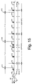
- the measurement in FIG. 3 either takes place, as shown, between "white” pulses, or, as shown on the right in FIG. 15, between “black” impulses.
- the measurement takes place between pulses 176 and 182.
- N 6 pulses are counted there, and the The time interval between the pulses 176 and 182 is determined and is ⁇ t (176-182). These two values then become according to the equation (1) speed information n is calculated.
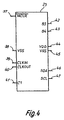
- FIG. 4 shows an overview of the connections of a ⁇ C 23 used in the exemplary embodiment, here of the PIC 16C72 type from Microchip.
- This is an 8 bit processor. It contains a 16 bit timer and an 8 bit timer, two PWM registers, and several interrupt functions. Naturally, this processor is only an example, but has proven itself in the described embodiment.
- the ⁇ C 23 has i.a. the connections MCLR 37, VSS 38, CLKIN 39, CLKOUT 40, C1 41, B5 42, B4 43, VDD 44, VSS 45, SDA 46 and SCL 47.
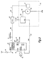
- Fig. 5 shows a circuit diagram of a preferred arrangement with an electric motor M, the speed of which is to be controlled.
- the connections of the ⁇ C 23 are shown in Fig. 4, and the corresponding Reference symbols are used further.
- the MCLR 37 connection is over a resistor 71 connected to a positive voltage + 5 V.
- the Connections CLKIN 39 and CLKOUT 40 are with an oscillator quartz 75 connected, which generates the clock frequency for the ⁇ C 23.
- the VDD connection 44 is connected to + 5 V, the connection VSS 45 to GND, and There is a capacitor 77 between the two connections.
- the ⁇ C 23 has two Timers TIMER0 and TIMER1 on, as well as a counter for the following described variable INT_CNT_f. Parts that are the same or have the same effect as 1 to 4 are given the same reference numerals.
- the frequency f (detected by the rotor position sensor 61) the speed of the motor M 32) reaches a filter FILT via a line 29 57, and from there via line 59 to connection B5 42 of the ⁇ C 23.
- the motor 32 has an actuator SG 63, which is the size of the affects the motor 32 flowing current.
- the actuator 63 is connected to a voltage + U_B via a line 33 connected, and a manipulated variable SW is the actuator SG 63 via a Line 27 supplied from the connection C1 of the ⁇ C 23. by the size of the To influence current that flows to motor M via SG63.
- the ⁇ C 23 receives its operating voltage via the connection VDD 44 + 5 V and VSS 45 to ground GND. Via a filter capacitor 77 Supply voltage secured against voltage peaks and dips.
- the connections SDA 46 and SCL 47 of the ⁇ C 23 are used for serial Transmission of data and can e.g. with an EEPROM or a external bus (not shown).
- the frequency f is supplied by the rotor position sensor 61, which is a constant number of pulses per revolution of the rotor 32 provides.
- Rotor position sensor 61 can e.g. a Hall generator or an optical one, mechanical, capacitive or inductive sensor can be used.
- the filter 57 is used to prepare the edges of the frequency f, so that at an edge change at the interruptible input B5 42 Hall interrupt 630 (Fig. 7) is triggered.
- the filter 57 can e.g. an RC link or be a Schmitt trigger. With a suitable signal f from sensor 61 the FILT 57 filter can also be omitted. An example of the effect of the filter is shown in Fig. 6.
- TIMER0 of the ⁇ C 23 is used to trigger the start signals 171, 173 (FIG. 3) Measurements used by at the corresponding points 171, 173 etc. triggers a TIMER0 interrupt 638 (Fig. 7).
- the TIMER1 of the ⁇ C 23 is used to determine the time difference ⁇ t (FIG. 3) used.
- the TIMER1 is preferably designed as a ring counter. That has the Advantage that the ring counter runs continuously and none during a measurement Bit is lost. This gives a very high speed detection Resolution that works on average with a measurement error of zero.
- the value of the TIMER1 is read out and saved with every interrupt. Should once two interrupts occur simultaneously, so a small one Measurement delay occur, but this will occur in the following measurement cycle automatically corrected because this then automatically becomes a little too short, because stopping one measurement is identical to starting the next Measurement, and the subsequent measurement is started before the current measured values can be evaluated.
- a manipulated value SW for the speed control calculated in the ⁇ C 23 is via connection C1 41 e.g. output as an analog voltage SW and via the line 27 to the actuator SG 63, which supplies the power controls for the M 32 engine.
- Actuator SG 63 can e.g. as an analog Longitudinal adjuster or as a PWM actuator.
- FIG. 6A shows the frequency f before it reaches the FILT 57 filter
- FIG. 6B shows the frequency f after it has been processed in the FILT 57 filter.
- the frequency f from FIG. 6A comes from a Hall generator, for example, and the edges 109 are less steep.
- the frequency f from FIG. 6B has been processed by the filter 57.
- the Flanks 110 are steep, and it can safely pass through each of the steep flanks 110
- An interrupt 630 (FIG. 7) is triggered in the ⁇ C 23, which follows Hall interrupt is called.
- the Hall interrupts correspond to the pulses here 165 to 168 of FIG. 1 and 175 to 182 of FIG. 3.
- FIG. 7 shows a flow chart with a possible embodiment of the overall program running in the ⁇ C 23.
- the main program begins under the interrupt routines. After this Switching on the motor M triggers an internal reset in the ⁇ C 23. In S600 initializes the ⁇ C 23.
- the function manager FCT_MAN regulates the sequence of the individual subroutines.
- a Communication function COMM in S604, which is the data transmission between the ⁇ C 23 and a (not shown) EEPROM or bus (Data line).
- S606 stands for any other time-critical Functions.
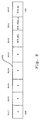
- FIG. 8 shows an exemplary function register 605 in which one bit is reserved for each function of FIG. 7.
- the remaining bits 3 to 7 are for other functions that can be requested reserved, which may be integrated in the function manager 601 can be.
- the speed calculation function CALC_n S616 (Fig. 7) is used for Calculation of the actual speed n.
- the controller function RGL S620 (Fig. 14) calculates the manipulated variable SW (FIG. 5) and sends it to the actuator SG 63 of the engine M.
- the function manager provides optimal use of the ⁇ C resources 23.
- the state diagram has four states S1, S2, S3 and S4 and six transitions T1, T2, ..., T6. Every transition has an event and an action.
- FIG. 10A schematically shows a four-pole permanent magnetic rotor 32 ′′ and a rotor position sensor 61, which is designed here, for example, as a Hall sensor.
- the rotor 32 '' has two south poles (S) 35 and 35 'and two north poles (N) 34 and 34'.
- the rotor position sensor 61 detects the rotor position signal f, which has a flank 110 each time the rotating rotor 32 ′′ changes from a north pole (N) to a south pole (S) or vice versa.
- a Hall interrupt 630 is triggered in the ⁇ C 23 (FIG. 7). Four Hall interrupts 630 are therefore triggered per revolution of the rotor 32 ′′.
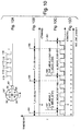
- 10B and 10C show an associated diagram with a Example sequence for measuring the frequency f.
- 10C shows the frequency signal f which is detected by the rotor position sensor 61.
- the two variables INT_MEAS_f (number of edge changes since the last measurement) and t_MEAS_f (time of the current measurement) are passed on to the speed calculation CALC_n, which is explained below in FIG. 13.
- INT_MEAS_f is calculated using an edge counter INT_CNT_f (in ⁇ C 23) determines which is reset to 0 each time a measurement is started and is increased by 1 on each edge 110.
- the value corresponds to INT_MEAS_f thus the variable N from FIG. 1 and FIG. 3, ie the number of measured Events 110.
- t_MEAS_f is determined with the help of TIMER1, which is preferably used as a ring counter is formed, which is a complete recording of successive values enabled by t_MEAS_f
- INT_MEAS_f (197-199), which is the number of edges in the Contains range from 197 to 199
- t_MEAS_f (199) which the Time of measurement at 199 contains the speed calculation CALC_n Handed over to S616.
- INT_MEAS_f (197-199) is e.g. 8, since eight flanks 110 be counted.
- FIG. 10D shows the value that results from the calculation of INT_CNT_f mod 4.
- the MODULO calculation with N mod MOD_f was explained in the description of FIG. 3.
- the value N corresponds to the value INT_CNT_f
- the value of INT_CNT_f mod 4 changes on each edge 110 of the signal f in accordance with the sequence of numbers 0, 1, 2, 3, 0, 1, 2, ..., namely when the motor is switched on.
- transition T1 from State S1 to S1.
- the event here is a through an edge 110 triggered Hall interrupt 630, and the action consists in counting the Edge 110 in the edge counter INT_CNT_f, and the storage of the current value of the ring counter TIMER1.
- Another event triggers the transition T2 from state S1 to state S2 out.
- the event is the occurrence of a timer TIMER0 triggered TIMER0 interrupts.
- the timer TIMER0 triggers in predefined Intervals T_A (Fig. 1, 3, 10B) a TIMER0 interrupt 638, e.g. to the Positions 191, 193, 195.
- T_A Fig. 1, 3, 10B
- TIMER0 interrupt 638 e.g. to the Positions 191, 193, 195.
- the associated interrupt routine TIMER0 interrupt S639 (FIGS. 7 and 11) the frequency measurement is released.
- the timer TIMER0 thus defines successive windows with the width T_A.
- the respective measurement does not exactly match the Events 191, 193 and 195 of the request instead of one suitable time, which is usually a little later.
- the size When measuring after a full revolution at the earliest, the size must be INT_CNT_f mod 4 have the same value for every measurement. Usually this will be zero, because then with a six-pole rotor with mod 6 (or mod 12) can be measured with a four-pole rotor mod 4 (or with mod 8), and with a two-pole rotor with mod 2 or mod 4, so that only the corresponding parameters 12, 8, 6, 4 or 2 in the ⁇ C 23 must be entered to move this to another engine switch.
- 10D is the result of INT_CNT_f mod 4 for the respective edge specified.
- An alternative way to determine the time ⁇ t_MEAS_f is to reset the time to zero at the beginning of each measurement. This can e.g. by setting the timer TIMER1 to zero. At the end of Measurement corresponds to the time in TIMER1 the value ⁇ t_MEAS_f. Hereby lies at positions 197, 199 and 201 directly INT_MEAS_f and ⁇ t_MEAS_f (cf. Fig. 2) before.
- a disadvantage of resetting the TIMER1 timer is that that it can then be used poorly for other measurements at the same time can.
- An instantaneous transition T6 leads from state S4 to state S1, and the frequency measurement is again in the initial state S1.
- T6 prepared the next measurement.
- the counter INT_CNT_f (for the number edges 110) are reset to zero (S330 in FIG. 12).
- T_A each initiated a new measurement. This makes the ⁇ C 23 for everyone Speeds or frequencies loaded equally.
- the present method has the advantage that the Measurement of signal f measured at least until the next interrupt becomes. So at some point, e.g. in the middle between two edges 110 lies, measured, but it is always from edge to Edge measured, i.e. from event to event, which is the accuracy of the Measurement significantly increased, cf. Fig. 10.
- a further increase in accuracy results in the measurement of a multiple of MOD_f edge changes, e.g. Measurement error due to Magnetization error in a permanent magnetic rotor or through Avoiding symmetry errors with a frequency supplied from outside become.
- This means e.g. with a four-pole motor that one measurement at the earliest on the fourth, on the 8th, on the 12th etc. edge change, namely whenever INT_CNT_f mod 4 0 (with a four-pole Four flanks 110 are generated per revolution).
- MOD_f is set to this fixed number A, see above that after each full turn in the same position of the Rotor 32 '' is measured. So it’s always measured at the event which is generated at a specific rotor position of the rotor 32 ′′. It is not necessary for this to happen that there is a special event is detected by the rotor position sensor 61 and in which it is known that a full turn has been made. Rather, everyone can Events per revolution of the rotor 32 '' be identical since the measurement of whole revolutions due to the special type of measurement with MOD_f expires automatically.
- This type of measurement is equally suitable for measuring one Frequency signal f, which the ⁇ C 23 from an external Frequency generator is supplied.
- Such signals may have f also asymmetries during a period of frequency f, e.g. on Zero crossing is slightly shifted in half the period, so that e.g. a measurement with mod 2 or mod 4 can have advantages and more precise Brings results.
- the rotor position signal f has events in the form of pulses at points 217, 218, 219, ..., 228.
- the pulses are alternately generated by the white mark 81 and the black mark 82 when they rotate past the rotor position sensor 61 and are therefore shown in white and black for better understanding.
- an interference pulse S occurs between the pulses 220 and 221. Control signals 211, 213 and 215 for requesting a measurement are also shown.
- a measurement usually ends / starts when by a Control signal 211, 213 or 215 a measurement is requested and also the The value of N mod 2 is zero if the rotor 32 'has been moving since the last one Measurement has rotated an integer multiple of a revolution.
- the interference pulse S causes that during the measurement in the period ⁇ t (218-223) it is assumed that the rotor 32 'between the pulses 220 and 221 has made a full turn even though it’s only half a turn Revolution.
- control signal 213 instead of the "white” signal 222 with the "black” signal 223 measured since N mod 2 no longer occurs after the interference pulse S in the "white” Pulses has the value zero, but with the "black” pulses.
- the measurement already works in the following period ⁇ t (223-227) but again correct, since now measured with "black" pulses becomes. There is therefore a shift in position due to the interference pulse S. of the rotor 32 'instead of which measurements are taken. The same would apply if a Impulse is missing.
- the measuring method therefore works according to an error signal S. really continues and continues to measure a multiple of a whole Revolution. This is an important advantage of this embodiment.
- FIGS. 11 and 12 show flowcharts for a program for the in 9 and 10 described measurement.
- FIG. 11 shows the routine TIMER0 interrupt S639 (FIG. 7), which requests the frequency measurement after the time T_A (FIG. 10), which then takes place in the routine Hall interrupt S631.
- TIMER0 interrupt 638 (Fig. 7) occurs, the TIMER0 interrupt routine S639 executed.
- a subtimer Subtimer_T_A begins in S354.
- Subtimer means that by the steps S356, S358 and S362 explained below are the actual ones Action in S360 only after a certain number of TIMER0 interrupts is triggered. This has the advantage that the TIMER0 timer can also be used by others Purposes can be used, which are called more often have to.
- the counter CNT_T_A is reset to zero by the Subtimer Subtimer_T_A to restart.
- S360 is called at locations 191, 193 and 195.
- FIG. 12 shows an exemplary embodiment for the interrupt routine Hall interrupt S631, which is executed for each Hall interrupt 630 triggered by the occurrence of an edge 110 (FIG. 4B) of the signal f.
- This interrupt is so named because it is usually triggered by the signal from a Hall generator 61 (in the motor M 32). Of course, it could also be triggered by an optical or mechanical sensor, and it could also be called a sensor-controlled interrupt.
- the routine Hall interrupt S631 ensures an electronically commutated Motor in COMMUT S304 for electronic commutation. This does not apply with a collector motor.
- MEAS_f S320 starts the acquisition and measurement of signal f.
- INT_CNT_f mod MOD_f 0 is used to check whether the value in Interrupt counter INT_CNT_f is a multiple of MOD_f.
- t_MEAS_f is based on the last recorded timer value t_END_f Ring counter TIMER1 set, INT_MEAS_f is set to the value of the Interrupt counter INT_CNT_f set, and INT_CNT_f becomes zero reset.
- the speed calculation CALC_n S616 (Fig. 13) is set requested by FCT_CALC_n to 1, and the measurement request is confirmed by Reset DO_MEAS_f reset to zero.
- Another way of calculating X mod MOD_f is e.g. in the use of a further variable MOD_CNT, which is used for each Increasing the variable X is also increased, and which when reached reset from MOD_f to zero.
- the variable MOD_CNT then gives the result of X mod MOD_f again.
- FIG. 13 shows the routine CALC_n S616, which is requested by the routine Hall interrupt (S332 in FIG. 12) after the measurement of the timer value t_MEAS_f and the number of edges 110 (FIG. 4) of the signal f in INT_MEAS_f.
- the difference between the timer value t_OLD_f is the last Measurement and the current timer value t_MEAS_f calculated and in the Variables ⁇ t_CALC_f are stored which correspond to the value ⁇ t_MEAS_f from FIG. 10 corresponds.
- the difference is usually calculated using the Two's complement formed.
- the current timer value t_MEAS_f is then stored in t_OLD_f for the next measurement, and the measured number of interrupts INT_MEAS_f is in INT_CALC_f saved.
- the interrupt counter INT_CALC_f which in this embodiment e.g. Is 4 bytes in size, is multiplied by const_f.
- const_f can either be chosen so that the result of the division in S372 the area which the value n, which e.g. two bytes or Is 16 bits, well exploited. This can e.g. can be achieved by const_f like this is chosen that the number of pulses at the maximum speed divided by the measurement window time T_A the speed approximately 2 ⁇ 15 (if the value n is 16 bits). This gives you a high one Accuracy, the speed n does not correspond to the speed n_phys, measured in rpm.
- INT_MEAS_f is one byte, INT_CALC four bytes and ⁇ t_CALC_f two bytes.
- INT_MEAS_f (197-199) has a value of 8, so it has been since the last Measurement at time t_MEAS_f (197) eight edges 110 of the Hall signal (Fig. 10A) counted.
- INT_CALC_f with const_f Multiplied 15,000,000 and receives the value 120,000,000.
- ⁇ t_MEAS_f (197-199) has - as an example - the value 26,700, which at a Resolution of the ring counter TIMER1 of 1 ⁇ s over a time of 26.7 ms corresponds.
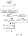
- FIG. 14 shows an example of a flowchart for an exemplary embodiment of the controller function RGL S620 (FIG. 7), which calculates a control value RGL_VAL from the speed n and a target speed n_s, which is predetermined, for example, and outputs it.
- a PI controller is shown in S352.
- the proportional component RGL_PROP is obtained by multiplying the Control difference RGL_DIFF calculated with the proportional factor RGL_P.
- the new integral part RGL_INT is obtained by adding the previous one Integral component and that multiplied by the integral factor RGL_I Control difference RGL_DIFF calculated.
- the integral part is preferred RGL_INT so much memory available that no information of the Control difference is lost.
- the manipulated variable RGL_VAL results from the sum of the proportional component RGL_PROP and the integral part RGL_INT.
- steps S534 to S540 a range check of the manipulated variable is carried out RGL_VAL performed.
- RGL_VAL If the value of RGL_VAL is within a permissible range, it becomes used unchanged.
- the present Invention can also be used in the context of other controllers, or also without a controller to measure a speed, or a frequency that is in the form a pulse train is supplied.
- the invention has been made in connection with described an electric motor because that's a preferred application represents, but is equally suitable for internal combustion engines, Turbines etc.
Landscapes
- Engineering & Computer Science (AREA)
- Power Engineering (AREA)
- Physics & Mathematics (AREA)
- General Physics & Mathematics (AREA)
- Control Of Motors That Do Not Use Commutators (AREA)
- Combined Controls Of Internal Combustion Engines (AREA)
- Control Of Electric Motors In General (AREA)
- Control Of Vehicle Engines Or Engines For Specific Uses (AREA)
Applications Claiming Priority (2)
| Application Number | Priority Date | Filing Date | Title |
|---|---|---|---|
| DE19945313 | 1999-09-22 | ||
| DE19945313 | 1999-09-22 |
Publications (2)
| Publication Number | Publication Date |
|---|---|
| EP1087232A1 true EP1087232A1 (fr) | 2001-03-28 |
| EP1087232B1 EP1087232B1 (fr) | 2008-01-09 |
Family
ID=7922835
Family Applications (1)
| Application Number | Title | Priority Date | Filing Date |
|---|---|---|---|
| EP00115977A Expired - Lifetime EP1087232B1 (fr) | 1999-09-22 | 2000-07-26 | Procédé pour la mesure d'une information fréquentielle, en particulier l'information de vitesse de rotation, et dispositif pour l'exécution d'un tel procédé |
Country Status (4)
| Country | Link |
|---|---|
| US (1) | US6496786B1 (fr) |
| EP (1) | EP1087232B1 (fr) |
| AT (1) | ATE383581T1 (fr) |
| DE (2) | DE50014906D1 (fr) |
Cited By (3)
| Publication number | Priority date | Publication date | Assignee | Title |
|---|---|---|---|---|
| CN100554968C (zh) * | 2005-11-11 | 2009-10-28 | 三星电子株式会社 | 用来获取编码器速度信息的电子装置及其方法 |
| DE102019119670A1 (de) * | 2019-07-19 | 2021-01-21 | Infineon Technologies Ag | Umdrehungszähler und Abtasten eines Drehwinkels |
| EP4096087A1 (fr) * | 2021-05-27 | 2022-11-30 | Hilti Aktiengesellschaft | Unité d'entraînement électrique pour une machine portative |
Families Citing this family (29)
| Publication number | Priority date | Publication date | Assignee | Title |
|---|---|---|---|---|
| US6831431B1 (en) * | 1999-09-22 | 2004-12-14 | Papst-Motoren Gmbh & Co. Kg | Method for regulating the rotational speed of a motor and a motor for carrying out a method of this type |
| DE50212540D1 (de) * | 2001-08-01 | 2008-09-04 | Ebm Papst St Georgen Gmbh & Co | Ür die zeitliche dauer eines sich periodisch wiederholenden impulsförmigen signals, und vorrichtung zur durchführung eines solchen verfahrens |
| JP4386649B2 (ja) * | 2003-01-21 | 2009-12-16 | 株式会社デンソー | 指針計器 |
| WO2007079511A2 (fr) * | 2006-01-10 | 2007-07-19 | Avl List Gmbh | Procede de determination d'un signal de vitesse de rotation pour une machine electrique |
| US9835265B2 (en) | 2011-12-15 | 2017-12-05 | Honeywell International Inc. | Valve with actuator diagnostics |
| US8947242B2 (en) | 2011-12-15 | 2015-02-03 | Honeywell International Inc. | Gas valve with valve leakage test |
| US9557059B2 (en) | 2011-12-15 | 2017-01-31 | Honeywell International Inc | Gas valve with communication link |
| US9995486B2 (en) | 2011-12-15 | 2018-06-12 | Honeywell International Inc. | Gas valve with high/low gas pressure detection |
| US8839815B2 (en) | 2011-12-15 | 2014-09-23 | Honeywell International Inc. | Gas valve with electronic cycle counter |
| US9846440B2 (en) | 2011-12-15 | 2017-12-19 | Honeywell International Inc. | Valve controller configured to estimate fuel comsumption |
| US9074770B2 (en) | 2011-12-15 | 2015-07-07 | Honeywell International Inc. | Gas valve with electronic valve proving system |
| US8905063B2 (en) | 2011-12-15 | 2014-12-09 | Honeywell International Inc. | Gas valve with fuel rate monitor |
| US8899264B2 (en) | 2011-12-15 | 2014-12-02 | Honeywell International Inc. | Gas valve with electronic proof of closure system |
| US9851103B2 (en) | 2011-12-15 | 2017-12-26 | Honeywell International Inc. | Gas valve with overpressure diagnostics |
| US9234661B2 (en) | 2012-09-15 | 2016-01-12 | Honeywell International Inc. | Burner control system |
| US10422531B2 (en) | 2012-09-15 | 2019-09-24 | Honeywell International Inc. | System and approach for controlling a combustion chamber |
| WO2014199018A1 (fr) * | 2013-06-12 | 2014-12-18 | Wärtsilä Finland Oy | Détermination de la vitesse angulaire dans un moteur |
| EP2868970B1 (fr) | 2013-10-29 | 2020-04-22 | Honeywell Technologies Sarl | Dispositif de régulation |
| US10024439B2 (en) | 2013-12-16 | 2018-07-17 | Honeywell International Inc. | Valve over-travel mechanism |
| US10404195B2 (en) | 2014-04-04 | 2019-09-03 | Robert Bosch Gmbh | Method, drive system and vehicle |
| CN106575104B (zh) * | 2014-08-13 | 2021-10-15 | 费希尔-罗斯蒙特系统公司 | 使用无线过程信号的模型预测控制 |
| US9841122B2 (en) | 2014-09-09 | 2017-12-12 | Honeywell International Inc. | Gas valve with electronic valve proving system |
| US9645584B2 (en) | 2014-09-17 | 2017-05-09 | Honeywell International Inc. | Gas valve with electronic health monitoring |
| US10503181B2 (en) | 2016-01-13 | 2019-12-10 | Honeywell International Inc. | Pressure regulator |
| US10564062B2 (en) | 2016-10-19 | 2020-02-18 | Honeywell International Inc. | Human-machine interface for gas valve |
| US10044302B2 (en) * | 2017-01-06 | 2018-08-07 | Honeywell International Inc. | Methods and apparatus for multi-mode motor speed calculation using digital hall effect sensors |
| JP6452210B1 (ja) * | 2017-09-12 | 2019-01-16 | Ckd日機電装株式会社 | 速度検出装置 |
| US11073281B2 (en) | 2017-12-29 | 2021-07-27 | Honeywell International Inc. | Closed-loop programming and control of a combustion appliance |
| US10697815B2 (en) | 2018-06-09 | 2020-06-30 | Honeywell International Inc. | System and methods for mitigating condensation in a sensor module |
Citations (4)
| Publication number | Priority date | Publication date | Assignee | Title |
|---|---|---|---|---|
| US4584528A (en) * | 1981-02-28 | 1986-04-22 | Hitachi, Ltd. | Speed detecting method and apparatus |
| GB2192103A (en) * | 1986-06-30 | 1987-12-31 | Eaton Corp | Pulse frequency detector |
| US5237521A (en) * | 1990-08-20 | 1993-08-17 | Xerox Corporation | High resolution position measurement system |
| US5502376A (en) * | 1994-05-24 | 1996-03-26 | Avtron Manufacturing, Inc. | Apparatus for controlling the duty cycle of a pulse generator |
Family Cites Families (11)
| Publication number | Priority date | Publication date | Assignee | Title |
|---|---|---|---|---|
| DE2949131A1 (de) | 1979-12-06 | 1981-06-11 | Deuta-Werke Vorm. Deutsche Tachometerwerke Gmbh, 5070 Bergisch Gladbach | Verfahren zum messen der geschwindigkeit von schienenfahrzeugen und vorrichtung zur durchfuehrung des verfahrens |
| JPS5759171A (en) | 1980-09-27 | 1982-04-09 | Toyota Motor Corp | Detection of rotating speed of rotating member in vehicle |
| US4612503A (en) * | 1980-10-21 | 1986-09-16 | Kabushiki Kaisha S G | Rotation speed detection device having a rotation angle detector of inductive type |
| US4485452A (en) | 1982-03-22 | 1984-11-27 | The Bendix Corporation | Speed measurement system |
| DE3709395A1 (de) | 1987-03-21 | 1988-09-29 | Licentia Gmbh | Verfahren und vorrichtung zur digitalen bestimmung einer der drehzahl eines koerpers proportionalen zahl |
| US4912661A (en) * | 1987-12-01 | 1990-03-27 | Hewlett-Packard Company | Tracking and resampling method and apparatus for monitoring the performance of rotating machines |
| US5445028A (en) * | 1992-09-18 | 1995-08-29 | Ametek Aerospace Products Inc. | Dynamic digital tracking filter |
| DE19530677A1 (de) | 1995-08-21 | 1997-02-27 | Siemens Ag | Verfahren zur Geschwindigkeits- oder Drehzahlmessung |
| DE19536840A1 (de) | 1995-10-02 | 1997-04-03 | Asea Brown Boveri | Verfahren zur Drehzahlmessung |
| JP2953502B2 (ja) * | 1996-06-28 | 1999-09-27 | 日本精機株式会社 | ステッピングモータ式計器の駆動装置 |
| EP0849598A1 (fr) | 1996-12-20 | 1998-06-24 | Mannesmann VDO Aktiengesellschaft | Procédé et appareil de détermination de la vitesse d'un objet en rotation, en particulier d'une roue d'un véhicule |
-
2000
- 2000-07-26 AT AT00115977T patent/ATE383581T1/de not_active IP Right Cessation
- 2000-07-26 EP EP00115977A patent/EP1087232B1/fr not_active Expired - Lifetime
- 2000-07-26 DE DE50014906T patent/DE50014906D1/de not_active Expired - Lifetime
- 2000-07-28 DE DE10036839A patent/DE10036839A1/de not_active Withdrawn
- 2000-09-19 US US09/665,498 patent/US6496786B1/en not_active Expired - Lifetime
Patent Citations (4)
| Publication number | Priority date | Publication date | Assignee | Title |
|---|---|---|---|---|
| US4584528A (en) * | 1981-02-28 | 1986-04-22 | Hitachi, Ltd. | Speed detecting method and apparatus |
| GB2192103A (en) * | 1986-06-30 | 1987-12-31 | Eaton Corp | Pulse frequency detector |
| US5237521A (en) * | 1990-08-20 | 1993-08-17 | Xerox Corporation | High resolution position measurement system |
| US5502376A (en) * | 1994-05-24 | 1996-03-26 | Avtron Manufacturing, Inc. | Apparatus for controlling the duty cycle of a pulse generator |
Cited By (6)
| Publication number | Priority date | Publication date | Assignee | Title |
|---|---|---|---|---|
| CN100554968C (zh) * | 2005-11-11 | 2009-10-28 | 三星电子株式会社 | 用来获取编码器速度信息的电子装置及其方法 |
| DE102019119670A1 (de) * | 2019-07-19 | 2021-01-21 | Infineon Technologies Ag | Umdrehungszähler und Abtasten eines Drehwinkels |
| US11441888B2 (en) | 2019-07-19 | 2022-09-13 | Infineon Technologies Ag | Turn counter and sensing of a rotational angle |
| EP4096087A1 (fr) * | 2021-05-27 | 2022-11-30 | Hilti Aktiengesellschaft | Unité d'entraînement électrique pour une machine portative |
| WO2022248383A1 (fr) * | 2021-05-27 | 2022-12-01 | Hilti Aktiengesellschaft | Unité d'entraînement électrique pour un outil motorisé à main |
| US12525904B2 (en) | 2021-05-27 | 2026-01-13 | Hilti Aktiengesellschaft | Electric drive unit for a hand-held power tool |
Also Published As
| Publication number | Publication date |
|---|---|
| DE50014906D1 (de) | 2008-02-21 |
| EP1087232B1 (fr) | 2008-01-09 |
| DE10036839A1 (de) | 2001-04-12 |
| US6496786B1 (en) | 2002-12-17 |
| ATE383581T1 (de) | 2008-01-15 |
Similar Documents
| Publication | Publication Date | Title |
|---|---|---|
| EP1087232B1 (fr) | Procédé pour la mesure d'une information fréquentielle, en particulier l'information de vitesse de rotation, et dispositif pour l'exécution d'un tel procédé | |
| EP1630363B1 (fr) | Méthode pour déterminer la phase d'un arbre à cames dans un moteur à combustion interne | |
| EP1214602B1 (fr) | Procede de regulation du regime d'un moteur et moteur permettant la mise en oeuvre dudit procede | |
| DE69603643T2 (de) | Positionsgeber | |
| DE10322689B4 (de) | Kurbelwinkel-Erfassungsvorrichtung | |
| DE19851942B4 (de) | Drehzahl-, Richtungs- und Beschleunigungssensor für eine rotierende Welle | |
| DE2645350C3 (de) | Elektronische Vorrichtung zur Zündsteuerung für Brennkraftmaschinen | |
| EP1118152B1 (fr) | Moteur a commutation electronique | |
| DE10233379A1 (de) | Verfahren zum Bestimmen eines numerischen Wertes für die zeitliche Dauer eines sich periodisch wiederholenden impulsförmigen Signals, und Vorrichtung zur Durchführung eines solchen Verfahrens | |
| EP2597429B1 (fr) | Procédé et agencement destiné à la détermination de l'état dynamique d'un moteur électrique | |
| WO2011121069A2 (fr) | Dispositif et procédé pour traiter des signaux qui représentent une position angulaire d'un arbre d'un moteur | |
| DE2642645A1 (de) | Digitales tachometer zur bestimmung und anzeige der drehzahl einer sich drehenden einrichtung | |
| DE60214588T2 (de) | Winkelgeschwindigkeitsaufnehmer | |
| DE102010016065A1 (de) | Verfahren zum Initialisieren eines Anzeigeinstruments für ein Fahrzeug | |
| EP2553399A2 (fr) | Procédé de traitement systématique d'erreurs | |
| DE3883012T2 (de) | Vorrichtung für die bestimmung der geschwindigkeit, der winkelposition und der rotationsrichtung einer rotierenden achse. | |
| EP1596493B1 (fr) | Procédé de mesure de la vitesse d'un moteur à commutation électronique | |
| DE102005035881A1 (de) | Verfahren zum Bestimmen der Drehwinkellage der Nockenwelle einer Hubkolben-Verbrennungsmaschine relativ zur Kurbelwelle | |
| DE2614858B2 (fr) | ||
| DE102005019515C5 (de) | Verfahren zum Messen der Drehzahl eines EC-Motors | |
| DE2943227A1 (en) | Device for measuring the frequency of a pulse generator and digital control system comprising such a device | |
| DE2723265A1 (de) | Verfahren und einrichtung zum steuern von betriebsparameterabhaengigen vorgaengen | |
| DE3718207A1 (de) | Verfahren zur steuerung der drehzahl eines rotors | |
| EP1400785A2 (fr) | Procédé de correction de l'erreur de mesure d'un capteur | |
| DE3933148C2 (de) | Vorrichtung und Verfahren zur Zylindererkennung für eine Mehrzylinderbrennkraftmaschine |
Legal Events
| Date | Code | Title | Description |
|---|---|---|---|
| PUAI | Public reference made under article 153(3) epc to a published international application that has entered the european phase |
Free format text: ORIGINAL CODE: 0009012 |
|
| 17P | Request for examination filed |
Effective date: 20001125 |
|
| AK | Designated contracting states |
Kind code of ref document: A1 Designated state(s): AT BE CH CY DE DK ES FI FR GB GR IE IT LI LU MC NL PT SE |
|
| AX | Request for extension of the european patent |
Free format text: AL;LT;LV;MK;RO;SI |
|
| AKX | Designation fees paid |
Free format text: AT BE CH CY DE DK ES FI FR GB GR IE IT LI LU MC NL PT SE |
|
| 17Q | First examination report despatched |
Effective date: 20061108 |
|
| GRAP | Despatch of communication of intention to grant a patent |
Free format text: ORIGINAL CODE: EPIDOSNIGR1 |
|
| RTI1 | Title (correction) |
Free format text: METHOD FOR MEASURING A FREQUENCY INFORMATION, IN PARTICULAR AN ANGULAR FREQUENCY INFORMATION OF A MOTOR, AND DEVICE FOR IMPLEMENTING SUCH A METHOD |
|
| RAP1 | Party data changed (applicant data changed or rights of an application transferred) |
Owner name: EBM-PAPST ST. GEORGEN GMBH & CO. KG |
|
| RAP1 | Party data changed (applicant data changed or rights of an application transferred) |
Owner name: EBM-PAPST ST. GEORGEN GMBH & CO. KG |
|
| GRAS | Grant fee paid |
Free format text: ORIGINAL CODE: EPIDOSNIGR3 |
|
| GRAA | (expected) grant |
Free format text: ORIGINAL CODE: 0009210 |
|
| AK | Designated contracting states |
Kind code of ref document: B1 Designated state(s): AT BE CH CY DE DK ES FI FR GB GR IE IT LI LU MC NL PT SE |
|
| REG | Reference to a national code |
Ref country code: GB Ref legal event code: FG4D Free format text: NOT ENGLISH |
|
| RIN1 | Information on inventor provided before grant (corrected) |
Inventor name: DIETERLE, ROLAND Inventor name: RAPPENECKER, HERMANN, DIPL.-ING. Inventor name: HAHN, ALEXANDER |
|
| REG | Reference to a national code |
Ref country code: CH Ref legal event code: EP |
|
| REG | Reference to a national code |
Ref country code: IE Ref legal event code: FG4D Free format text: LANGUAGE OF EP DOCUMENT: GERMAN |
|
| REF | Corresponds to: |
Ref document number: 50014906 Country of ref document: DE Date of ref document: 20080221 Kind code of ref document: P |
|
| GBT | Gb: translation of ep patent filed (gb section 77(6)(a)/1977) |
Effective date: 20080225 |
|
| PG25 | Lapsed in a contracting state [announced via postgrant information from national office to epo] |
Ref country code: NL Free format text: LAPSE BECAUSE OF FAILURE TO SUBMIT A TRANSLATION OF THE DESCRIPTION OR TO PAY THE FEE WITHIN THE PRESCRIBED TIME-LIMIT Effective date: 20080109 |
|
| NLV1 | Nl: lapsed or annulled due to failure to fulfill the requirements of art. 29p and 29m of the patents act | ||
| PG25 | Lapsed in a contracting state [announced via postgrant information from national office to epo] |
Ref country code: ES Free format text: LAPSE BECAUSE OF FAILURE TO SUBMIT A TRANSLATION OF THE DESCRIPTION OR TO PAY THE FEE WITHIN THE PRESCRIBED TIME-LIMIT Effective date: 20080420 Ref country code: FI Free format text: LAPSE BECAUSE OF FAILURE TO SUBMIT A TRANSLATION OF THE DESCRIPTION OR TO PAY THE FEE WITHIN THE PRESCRIBED TIME-LIMIT Effective date: 20080109 |
|
| ET | Fr: translation filed | ||
| PG25 | Lapsed in a contracting state [announced via postgrant information from national office to epo] |
Ref country code: PT Free format text: LAPSE BECAUSE OF FAILURE TO SUBMIT A TRANSLATION OF THE DESCRIPTION OR TO PAY THE FEE WITHIN THE PRESCRIBED TIME-LIMIT Effective date: 20080609 |
|
| REG | Reference to a national code |
Ref country code: IE Ref legal event code: FD4D |
|
| PG25 | Lapsed in a contracting state [announced via postgrant information from national office to epo] |
Ref country code: DK Free format text: LAPSE BECAUSE OF FAILURE TO SUBMIT A TRANSLATION OF THE DESCRIPTION OR TO PAY THE FEE WITHIN THE PRESCRIBED TIME-LIMIT Effective date: 20080109 Ref country code: IE Free format text: LAPSE BECAUSE OF FAILURE TO SUBMIT A TRANSLATION OF THE DESCRIPTION OR TO PAY THE FEE WITHIN THE PRESCRIBED TIME-LIMIT Effective date: 20080109 Ref country code: SE Free format text: LAPSE BECAUSE OF FAILURE TO SUBMIT A TRANSLATION OF THE DESCRIPTION OR TO PAY THE FEE WITHIN THE PRESCRIBED TIME-LIMIT Effective date: 20080409 |
|
| PLBE | No opposition filed within time limit |
Free format text: ORIGINAL CODE: 0009261 |
|
| STAA | Information on the status of an ep patent application or granted ep patent |
Free format text: STATUS: NO OPPOSITION FILED WITHIN TIME LIMIT |
|
| 26N | No opposition filed |
Effective date: 20081010 |
|
| PG25 | Lapsed in a contracting state [announced via postgrant information from national office to epo] |
Ref country code: MC Free format text: LAPSE BECAUSE OF NON-PAYMENT OF DUE FEES Effective date: 20080731 |
|
| PG25 | Lapsed in a contracting state [announced via postgrant information from national office to epo] |
Ref country code: CY Free format text: LAPSE BECAUSE OF FAILURE TO SUBMIT A TRANSLATION OF THE DESCRIPTION OR TO PAY THE FEE WITHIN THE PRESCRIBED TIME-LIMIT Effective date: 20080109 |
|
| PG25 | Lapsed in a contracting state [announced via postgrant information from national office to epo] |
Ref country code: AT Free format text: LAPSE BECAUSE OF NON-PAYMENT OF DUE FEES Effective date: 20080726 |
|
| PG25 | Lapsed in a contracting state [announced via postgrant information from national office to epo] |
Ref country code: LU Free format text: LAPSE BECAUSE OF NON-PAYMENT OF DUE FEES Effective date: 20080726 |
|
| PG25 | Lapsed in a contracting state [announced via postgrant information from national office to epo] |
Ref country code: BE Free format text: LAPSE BECAUSE OF NON-PAYMENT OF DUE FEES Effective date: 20080731 |
|
| PG25 | Lapsed in a contracting state [announced via postgrant information from national office to epo] |
Ref country code: GR Free format text: LAPSE BECAUSE OF FAILURE TO SUBMIT A TRANSLATION OF THE DESCRIPTION OR TO PAY THE FEE WITHIN THE PRESCRIBED TIME-LIMIT Effective date: 20080410 |
|
| REG | Reference to a national code |
Ref country code: DE Ref legal event code: R084 Ref document number: 50014906 Country of ref document: DE |
|
| REG | Reference to a national code |
Ref country code: FR Ref legal event code: PLFP Year of fee payment: 17 |
|
| REG | Reference to a national code |
Ref country code: FR Ref legal event code: PLFP Year of fee payment: 18 |
|
| REG | Reference to a national code |
Ref country code: FR Ref legal event code: PLFP Year of fee payment: 19 |
|
| REG | Reference to a national code |
Ref country code: DE Ref legal event code: R085 Ref document number: 50014906 Country of ref document: DE |
|
| PGFP | Annual fee paid to national office [announced via postgrant information from national office to epo] |
Ref country code: IT Payment date: 20190531 Year of fee payment: 20 |
|
| PGFP | Annual fee paid to national office [announced via postgrant information from national office to epo] |
Ref country code: FR Payment date: 20190612 Year of fee payment: 20 |
|
| PGFP | Annual fee paid to national office [announced via postgrant information from national office to epo] |
Ref country code: CH Payment date: 20190625 Year of fee payment: 20 |
|
| PGFP | Annual fee paid to national office [announced via postgrant information from national office to epo] |
Ref country code: DE Payment date: 20190701 Year of fee payment: 20 |
|
| PGFP | Annual fee paid to national office [announced via postgrant information from national office to epo] |
Ref country code: GB Payment date: 20190902 Year of fee payment: 20 |
|
| REG | Reference to a national code |
Ref country code: DE Ref legal event code: R071 Ref document number: 50014906 Country of ref document: DE |
|
| REG | Reference to a national code |
Ref country code: CH Ref legal event code: PL |
|
| REG | Reference to a national code |
Ref country code: GB Ref legal event code: PE20 Expiry date: 20200725 |
|
| PG25 | Lapsed in a contracting state [announced via postgrant information from national office to epo] |
Ref country code: GB Free format text: LAPSE BECAUSE OF EXPIRATION OF PROTECTION Effective date: 20200725 |