EP1087237A2 - Appareil de mesure de position des moyens de prise de charge pour un dispositif de levage - Google Patents
Appareil de mesure de position des moyens de prise de charge pour un dispositif de levage Download PDFInfo
- Publication number
- EP1087237A2 EP1087237A2 EP00121039A EP00121039A EP1087237A2 EP 1087237 A2 EP1087237 A2 EP 1087237A2 EP 00121039 A EP00121039 A EP 00121039A EP 00121039 A EP00121039 A EP 00121039A EP 1087237 A2 EP1087237 A2 EP 1087237A2
- Authority
- EP
- European Patent Office
- Prior art keywords
- radar
- active reflector
- reflector unit
- measuring device
- signal
- Prior art date
- Legal status (The legal status is an assumption and is not a legal conclusion. Google has not performed a legal analysis and makes no representation as to the accuracy of the status listed.)
- Withdrawn
Links
Images


Classifications
-
- B—PERFORMING OPERATIONS; TRANSPORTING
- B66—HOISTING; LIFTING; HAULING
- B66C—CRANES; LOAD-ENGAGING ELEMENTS OR DEVICES FOR CRANES, CAPSTANS, WINCHES, OR TACKLES
- B66C13/00—Other constructional features or details
- B66C13/18—Control systems or devices
- B66C13/46—Position indicators for suspended loads or for crane elements
-
- G—PHYSICS
- G01—MEASURING; TESTING
- G01S—RADIO DIRECTION-FINDING; RADIO NAVIGATION; DETERMINING DISTANCE OR VELOCITY BY USE OF RADIO WAVES; LOCATING OR PRESENCE-DETECTING BY USE OF THE REFLECTION OR RERADIATION OF RADIO WAVES; ANALOGOUS ARRANGEMENTS USING OTHER WAVES
- G01S13/00—Systems using the reflection or reradiation of radio waves, e.g. radar systems; Analogous systems using reflection or reradiation of waves whose nature or wavelength is irrelevant or unspecified
- G01S13/74—Systems using reradiation of radio waves, e.g. secondary radar systems; Analogous systems
- G01S13/82—Systems using reradiation of radio waves, e.g. secondary radar systems; Analogous systems wherein continuous-type signals are transmitted
-
- G—PHYSICS
- G01—MEASURING; TESTING
- G01S—RADIO DIRECTION-FINDING; RADIO NAVIGATION; DETERMINING DISTANCE OR VELOCITY BY USE OF RADIO WAVES; LOCATING OR PRESENCE-DETECTING BY USE OF THE REFLECTION OR RERADIATION OF RADIO WAVES; ANALOGOUS ARRANGEMENTS USING OTHER WAVES
- G01S13/00—Systems using the reflection or reradiation of radio waves, e.g. radar systems; Analogous systems using reflection or reradiation of waves whose nature or wavelength is irrelevant or unspecified
- G01S13/74—Systems using reradiation of radio waves, e.g. secondary radar systems; Analogous systems
- G01S13/82—Systems using reradiation of radio waves, e.g. secondary radar systems; Analogous systems wherein continuous-type signals are transmitted
- G01S13/84—Systems using reradiation of radio waves, e.g. secondary radar systems; Analogous systems wherein continuous-type signals are transmitted for distance determination by phase measurement
-
- G—PHYSICS
- G01—MEASURING; TESTING
- G01S—RADIO DIRECTION-FINDING; RADIO NAVIGATION; DETERMINING DISTANCE OR VELOCITY BY USE OF RADIO WAVES; LOCATING OR PRESENCE-DETECTING BY USE OF THE REFLECTION OR RERADIATION OF RADIO WAVES; ANALOGOUS ARRANGEMENTS USING OTHER WAVES
- G01S13/00—Systems using the reflection or reradiation of radio waves, e.g. radar systems; Analogous systems using reflection or reradiation of waves whose nature or wavelength is irrelevant or unspecified
- G01S13/87—Combinations of radar systems, e.g. primary radar and secondary radar
- G01S13/874—Combination of several systems for attitude determination
Definitions
- the invention relates to a measuring device for determining the position of load suspension devices for hoists.
- Such measuring devices come with increasing distribution used especially with container cranes, by means of which a safe reception, a safe transport and a safe and precisely placed a container must become.
- a safe reception, a safe transport and a safe and precisely placed a container must become.
- the invention is based on the object mentioned Measuring device for determining the position of load suspension devices to train in hoists such that their Functionality even under the mentioned difficult conditions remains reliably guaranteed.
- the Measuring device is designed as a microwave measuring system. Because of this configuration of the measuring device can also be used adverse environmental conditions or influences, such as Nebei, Rule, snow, dust clouds etc., the measurement accuracy of the Measuring device can still be ensured.
- the configuration of the Measuring device proved as a radar system.
- Such a radar system advantageously has at least one Radar sensor and at least one active reflector unit. Depending on the requirements for the detection of spatial movement of the load handler or one attached to it
- Such a radar system can contain the desired container Number of radar sensors or active reflector units have, optionally the number of radar sensors or the number of active reflector units or the number both of the radar sensors as well as the active reflector units can be changed.
- the radar sensor expediently has a radar module an oscillator for signal generation and a processor for Control and evaluation of the radar signals.
- the oscillator of the radar module is advantageously in its Frequency adjustable.
- the radar sensor has an antenna by means of which the radar signal with the frequency determined by the oscillator in the direction can be radiated onto the active reflector unit.
- the radar sensor should advantageously have a device for evaluation have, by means of which the phase difference between that emitted to the active reflector unit and that of radar signal reflected by the active reflector unit can be detected is.
- the device on the radar sensor for detecting the phase difference between the radar signal emitted and the one received can have a mixer and a filter.
- the active reflector unit expediently has a receiving antenna, radar signals emitted by the front radar sensor are receivable.
- the active reflector unit also has an amplifier for amplifying a radiated by the radar sensor and by your received radar signal.
- each active reflector unit has a modulator has, by means of which the radar signal received by it is modulable before it is active by the concerned Reflector unit is reflected to the radar sensor.
- the active reflector unit advantageously has one Transmitting antenna, by means of which in the modulator of the active reflector unit modulated radar signal back to the radar sensor is radiated.
- the active reflector unit can be a combined one Transmit and receive antenna if they have a directional coupler, e.g. has a circulator.
- the modulator expediently modulates each active reflector unit the radar signal it receives in one characteristic for the active reflector unit in question Way so that the modulated and sent to the radar sensor reflected radar signal from the radar sensor of the concerned active reflector unit can be assigned.
- the reflected radar signal can be modulated, by amplifying the amplifier of the active reflector unit changed during the reflection of the radar signal becomes.
- the active reflector unit for Radar sensor also reflected radar signal in the desired way Be modulated so that the active reflector unit a means of delaying the time from it to Radar sensor to reflect radar signal.
- the means for time delay on the reflector unit side of the radar signal to be reflected can advantageously be used as Runtime element can be formed by means of which to be reflected Radar signal can be delayed by a defined time offset is.
- the means for delaying the time can be advantageous reflective radar signal formed as a surface element his.
- a resonator structure from which the Modulation frequency can be derived is applied on a substrate, on which a delay line of the delay element is formed is applied.
- the modulation of the active reflector unit to the radar sensor to be reflected radar signal be accomplished in that the active reflector unit a means of translating the frequency to be reflected Has radar signal.
- the means for frequency offset on the reflector unit side can advantageously be designed as a mixer module by means of which the radar signal received by the active reflector unit is frequency miscible with a reference signal.
- the mixer module on the reflector unit side is expedient designed as a double sideband or single sideband mixer.
- the modulation of the from the active reflector unit to the radar sensor radar signal to be reflected can furthermore can be achieved in that the active reflector unit Means for alternating phase change of the to be reflected Has radar signal.
- the reflector unit-side means for alternating phase change of the radar signal to be reflected expediently designed as a controllable phase shifter his.
- the radar sensor of the radar system according to the invention is advantageous designed so that the active reflector unit modulated radar signal reflected at him in such a way it can be demodulated to be contained in this radar signal useful signal serving as the basis for the distance measurement Interference signal components can be reduced.
- the radar sensor is according to another advantageous Embodiment of the radar system according to the invention formed such that that of several active reflector units modulated and reflected radar signals are separable in the radar sensor.
- the radar sensor advantageously has a reduction in the radar signal contained interference signal components a bandpass filtering and to separate the from different active reflector units a suitable demodulation stage on.
- a technically and structurally simple and economically little costly design of the measuring device according to the invention or radar system is reached if the at least a radar sensor of the measuring device on the hoist and the at least an active reflector unit on the load handler is arranged.
- the three active reflector units so am Spreader of the container crane are arranged so that they are one have the greatest possible distance from each other.
- the radar sensor can be used to generate the radar signal Have signal generator.
- the radar sensor also advantageously has a directional coupler, by means of which the radar signal generated via the antenna in Direction of the active reflector units can be emitted.
- the radar sensor has a mixer by means of which the received reflected radar signals are mixable down to baseband.
- the radar sensor can have a filter device, by means of which the spectral components of the received reflected Select radar signals and the radar signal components all active reflector units are separable.
- the radar sensor has an A / D converter, by means of the the received reflected radar signals into digital signals are convertible so that their filtering is digital in the processor of the radar sensor is feasible.
- the filter device can then advantageously be used as an anti-aliasing low-pass filter, preferably as a bandpass filter, be formed by means of which the active reflector units assignable radar signal components pass-through and others Radar signal components can be suppressed.
- a measured variable for Position determination of the load suspension device is used as a measured variable for Position determination of the load suspension device, the phase difference or the temporal change in the phase difference between a transmitted and a received microwave, preferably Radar signal.
- a radar sensor expediently carries out a measurement at least through two different radar frequencies and forms by evaluating the phase differences from the transmitted and the received radar signal at the different radar frequencies a measure of distance and / or change in distance between the radar sensor and an active reflector unit.
- the distance values between the or all Radar sensors of one and the or all active reflector units on the other hand be determined at the same time.
- Each active reflector unit advantageously modulates that of their received radar signal in a characteristic for them Way, with each radar sensor modulating that and reflected radar signal of the active one concerned Assigns reflector unit.
- Each active reflector unit modulates what it receives Radar signal in a manner characteristic of them so that the radar signals modulated in this way are different active reflector units separated in the radar sensor can be.
- an active reflector unit received radar signal modulated and to a radar sensor reflected, and that reflected to the radar sensor modulated radar signal in the radar sensor demodulated such that contained in this radar signal, as the basis of the distance measurement Serving useful signal interfering interference signal components be reduced.
- For modulating the from the active reflector unit to the radar sensor reflected radar signal can amplify a Amplifier of the active reflector unit during the reflection of the radar signal can be changed.
- the change in the reinforcement of the amplifier can active reflector unit can be varied in small steps.
- Barker codes shift register (M) sequences
- Golay codes gold codes or Huffmann sequences be used.
- a suitable modulation of that of the active reflector unit radar signal reflected to the radar sensor can also be accomplished be by the amplifier of the concerned active reflector unit during the reflection of the radar signal is switched on and off alternately.
- each active reflector unit Clock is chosen so that the reflected radar signals do not overlap spectrally in the spectral useful band.
- Another suitable modulation method can be found in the time delay of the active reflector unit to the radar sensor to be reflected radar signal.
- the time delay of the radar signal to be reflected can advantageously carried out by means of a surface wave element become.
- time delay should be chosen so large that interference signal components, for example caused by reflections on objects in the measuring range, due to the damping of propagation mostly subside in the open space.
- the time delay is expediently active for each Reflector unit selected different sizes.
- An even more reliable assignment of the radar signals to the the active reflector units emitting can be achieved be when an amplitude modulation of the radar signal by means of Adjustment or switching the amplifier on and off is combined with the time delay of the radar signal.
- the modulation frequency e.g. 1 MHz
- the time delay e.g. 1 ⁇ s
- the incoming radar signals are advantageous on the radar sensor side by means of an FMCW (freguency modulated continous wave) radar selection process separated and the respective active Assigned reflector units.
- FMCW frequency modulated continous wave
- radar signal radiated onto the radar sensor can also a frequency offset from that of the active reflector unit serve reflected radar signal.
- the radar signal to be reflected alternating in phase from the active reflector unit will be changed.
- Measuring device in terms of its basic design Measuring device according to the invention shown is as a microwave measuring system designed in the form of a radar system 1.
- a microwave measuring system designed in the form of a radar system 1.
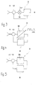
- the embodiment of the radar system shown in FIG 1 is a radar sensor 2 and an active reflector unit 3 intended.
- the radar sensor 2 comprises a radar module 4 and a processor 5.
- the radar module 4 can be a signal generating element in the form of a Contain oscillator, the oscillator expediently its frequency is adjustable.
- the processor 5 is used to control and evaluate the reflected from the active reflector unit 3 to the radar sensor 2 Measurement or radar signals.
- the radar sensor 2 has an antenna 6, by means of which or by means of which a radar signal with the frequency F HF determined by the frequency-adjustable oscillator of the radar module 4 can be emitted in the direction of the active reflector unit 3.
- the active reflector unit 3 has that shown in FIG Embodiment a receiving antenna 7, by means of which from the radar sensor 2 towards the active reflector unit 3 radar signal can be received. From the receiving antenna 7, the radar signal to an amplifier 8 of the active Reflector unit 3 forwarded. That in amplifier 8 amplified radar signal is a modulator 9 of the active reflector unit 3 fed and modulated there. That in the modulator 9 modulated radar signal is then via a transmitting antenna 10 of the active reflector unit 3 back towards the Radar sensor 2 reflects or illuminates.
- the measuring device according to the invention is a plurality of Radar sensors 2 are provided, one on the left in FIG are shown. Furthermore, the one shown in FIG Measuring device or radar system also a variety of active reflector units 3, one on the right in FIG. 2 are shown. With appropriate configuration of the in 2 radar system shown, each radar sensor 2 with each active reflector unit 3 communicate, with each other a corresponding number of measuring paths for recording distances or changes in distance.
- the active ones shown there Reflector units each only a combined transmit and Receiving antenna 11.
- Such a combined transmission and Receiving antenna 11 can be implemented with active reflector units 3, the, as shown in Figures 3 to 5, a Directional coupler 12, e.g. have a circulator.
- Radar systems 1 also possible, the radar sensor 2 with both a transmitting and a receiving antenna equip.
- the radar sensor 2 has a device for determining the Phase difference between the radar signal emitted by it and that reflected from the active reflector unit 3 to it Radar signal on.
- This facility for capturing the phase difference between the mentioned radar signals can, as can be seen in particular from FIG. 7, a mixer 13 and have a filter 14, on their function and interaction will be discussed later.
- phase values detected in the manner mentioned can then in the processor 5 of the radar sensor 2 in later determined manner described a change in distance become.
- Phase values that are at least two different Radar frequencies have been determined can be an absolute Distance measurement in a manner to be described be carried out in the processor 5 of the radar sensor 2.
- the active reflector units 3 on the load suspension device attached the radar sensor 2 preferably accordingly is arranged on the hoist. In principle, however an equivalent arrangement in the opposite way possible.
- the radar sensor 2 and / or several active reflector units 3 it is necessary several radar sensors 2 and / or several active reflector units 3 to use dimensional alignment of the load handler in relation to the hoist to be able to determine.
- trained hoist becomes the degree of freedom of movement of the load suspension means designed as a spreader 16 the choice of the lifting mechanism, e.g. by the type of stranding 17 set.
- the arrangement of the radar sensors 2 and of the active reflector units 3 is in a radar system 1 for such a container crane 15 preferably to adapt to this.
- each active reflector unit 3 contains a means for this Frequency offset in the form of a mixer module 18.
- This Mixer module 18 frequency mixes the incoming from radar sensor 2 Radar signal with a reference signal fs1.
- the mixer module 18 is provided with a double-side band or single-side band mixer.
- the single sideband mixer is that arriving from the radar sensor 2 Radar signal offset in frequency from the active reflector unit 3 sent back to the radar sensor 2 or reflected and occurs in the spectrum of the sensor signal at the offset frequency on.
- a suitable bandpass filtering subsequent demodulation false echoes can be suppressed; when using different modulation frequencies at different active reflector units 3 Radar signal components of different active reflector units 3 are separated from each other in the radar sensor 2.
- Reflector unit 3 is the modulation of the active Reflector unit 3 for radar sensor 2 reflected radar signal by means of a phase change means in the form of a controllable phase shifter 19.
- This controllable phase shifter 19 changes the radar signal arriving from the radar sensor 2 regarding the phase. The change of phase will carried out according to known schemes.
- radar signals can be accomplished by reflecting to the radar sensor 2 Radar signals in each active reflector unit 3 ⁇ m a defined time delay can be delayed.
- the relevant active reflector units 3 are a means for Time delay in the form of a delay element 20.
- the Time delay should be chosen so large that others Interference signal components, for example caused by reflections on objects in the measuring range, due to the damping of propagation mostly subside in the open space.
- the time delay values are different for each active reflector unit 3 chosen so that the radar signal components of the different active reflector units 3 in the radar sensor 2 for example by means of known FMCW (freguency modulated continous wave) radar evaluation method clearly separated can be.
- FMCW frequency modulated continous wave
- FIG 8 Delay lines 21 of the delay elements 20 are as can also be seen from FIG. 8, in the form of surface wave elements 22 executed.
- a phase measurement is suitable only one radar frequency only for the determination of differential Distance changes.
- An absolute position value can only do this by continuously determining the change in distance relative to a calibration measurement to the calibration reference point. With a continuous Measurement is to ensure that the measurement happens so quickly that between two measurements none so large distance change takes place which is a phase change would result in greater than 180 degrees. This condition corresponds to the well-known sampling theorem.
- a Continuous tracking of the phase is often called Doppler measurement, the time derivative of the Phase corresponds to the Doppler frequency.
- the Doppler frequency is proportional to the relative speed between the radar sensor 2 and active reflector unit 3 in the direction of signal transmission.
- Particularly advantageous for high-precision position measurement is to change the phase over time at a radar frequency, the differential distance measurement with which Phase difference values for several radar frequency values, that is the absolute distance measurement.
- the absolute measured values are e.g. through the essential corrected more accurate differential change values. Analogous to the above explanations, there is also one ensure that the measuring process is sufficiently fast.
- Phase locked loops are particularly suitable for this and direct digital signal synthesis.
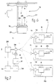
- Radar system 1 in connection with that in principle in FIG. 6 shown container crane 15 explained.
- the radar sensor 2 of the radar system 1 is on a crane trolley 23 of the container crane 15 attached.
- the spreader 16 is used to hold a container 27, which by means of Container crane 15 picked up, transported and set down shall be.
- the active reflector units 24, 25, 26 are on the spreader 16 arranged so that there is as large as possible between them Distance. This ensures that a lateral Deflection of the spreader 16 in relation to the crane trolley 23 Max. different changes in distance within the Measuring paths between your radar sensor 2 on the one hand and the active one Reflector units 24, 25, 26 leads on the other hand.
- the embodiment chosen in the embodiment according to FIG. 6 the radar system 1 with a radar sensor 2 and three active Reflector units 24, 25, 26 and arrangement of one radar sensor 2 on the crane trolley 23 and the three active reflector units 24, 25, 26 on the spreader 16 of the container crane 15 has the advantage of a particularly simple attachment and one cost-effective feasibility.
- the radar sensor 2 is to attach to the crane trolley 23 so that it is as simple as possible to assemble and maintain. Provided several radar sensors 2 would be provided, they would have to be as far apart as possible be attached to the crane trolley 23. This could be in generally cannot be guaranteed as it is on the crane cat 23 little accessible places. Therefore at of the embodiment shown in FIG. 6 is the only one provided Radar sensor 2 on the crane trolley 23, e.g. on a mounting hole installed in the area of the cab.
- the assembly of the locally distributed active reflector units 3 on the spreader 16 of the container crane 15 is comparative easily possible because the spreader 16 to the ground can be lowered and thus easily accessible from all sides is.
- the embodiment shown in FIG. 6 is inexpensive the radar system 1 because the entire radar signal processing within the only provided radar sensor 2 can be carried out; an expensive transfer of Measurement data for a central unit or the use of several Processors 5 are therefore not necessary.
- the radar sensor 2 the radar system 1 is generally significantly more complex than the active reflector units 3 of the radar system 1.
- FIG. 1 A possible embodiment of the radar system 1 with the radar sensor 2 and the three active reflector units 24, 25, 26 is shown in FIG.
- the one to be emitted by the radar sensor 2 Radar signal is generated with the help of an oscillator Signal generator 28 generated.
- the radar signal thus generated is via the Antenna 6 of the radar sensor 2 in the direction of the active reflector units 24, 25, 26 emitted.
- the combined Transmitting and receiving antennas 11 of the active reflector units 24, 25, 26 receive the signal and send it to the amplifier 8 each active reflector unit 24, 25, 26 further.
- the Amplifier 8 amplifies the radar signal received by it.
- the directional coupler 12 of the active reflector units 24, 25, 26 decouples the radar signal to be reflected from the received one Radar signal. Via the combined transmitting and receiving antenna 11 of the active reflector units 24, 25, 26 will radar signal to be reflected sent back to radar sensor 2.
- each active reflector unit 24, 25, 26 To be able to separate radar signals in radar sensor 2, the amplifier 8 of each active reflector unit 24, 25, 26 with a characteristic clock fs1, fs2 and fs3, respectively switched off.
- This for each active reflector unit 24, 25, 26 characteristic clock is to be chosen so that those from the active reflector units 24, 25, 26 to the radar sensor 2 reflected radar signals in the selected spectral range Useful band, e.g. spectrally do not overlap by fs1, fs2 and fs3.
- the mixer 13 of the radar sensor 2 receives the reflected by the active reflector units 24, 25, 26 Radar signals mixed down to baseband. Next Frequency components around 0 Hz result in signal components the characteristic of the active reflector units 24, 25, 26 Switching frequency fs1, fs2 or fs3 and their multiples.
- the spectral components can be selected by bandpass filtering and the radar signal components of all active reflector units 24, 25, 26 are separated from each other.
- the filtering can either be done by circuitry by means of a filter 14 designed as a filter bank or in a digital manner in the processor 5, in which case one A / D conversion in an A / D converter arranged downstream of the filter 14 30 is to be made.
- the last-mentioned digital processing has the advantage that filters high order algorithmically easier too are realized and the actual signal separation only in Processor 5 takes place so that only one A / D converter 30 is required becomes.
- the Filter 14 as an anti-aliasing low-pass filter or preferably designed as a bandpass filter that around all three signal components those characteristic of the active reflector units 24, 25, 26 Allows switching frequencies fs1, fs2 and fs3 to pass, the remaining higher or lower frequency interference components, however suppressed.
- the three separate bandpass filtered signal components on an equal base frequency can be downmixed if, for example the first signal component with fs1, the second Signal component mixed with fs2 and the third signal component with fs3 becomes.
- the signal phase values for each Measuring path between the radar sensor 2 and the active one in question Reflector unit 24, 25 and 26 for several radar signal frequencies certainly. In the way described above these signal phase values are then converted into distance values. By continuously evaluating several successive ones Measurements are also the changes in distance certainly. From the distance values as well as the associated changes in distance are calculated using a triangulation calculation the position of the spreader 16 with respect to the crane trolley 23 and the spatial movement of the spreader 16 calculated.
- FIG. 8 shows an exemplary embodiment for a modulator 9 an active reflector unit 3 shown.
- this modulator 9 is an amplitude modulation with a time delay combined. This is the amplification of the amplifier 8 of the active reflector unit 3 at regular intervals on and off.
- This modulation frequency is preferably chosen to be inverse with the time delay of the delay element 20 of the modulator 9 is coupled. With a modulation frequency of 1 MHz, this results in a Time delay of 1 ⁇ s.
- the delay line 21 of the delay element 20 is in the form it realizes surface wave element 22, it is special favorable if directly on a substrate 31 on which the delay line 20 or delay line constructed is applied to a resonance structure 32 from which the frequency of modulation is derived. This will in optimally ensures that runtime changes due of temperature drifts and aging of the substrate 31 a proportional change of the resonance structure 32 apply applied modulation frequency; i.e. there Time delay and modulation frequency on the same substrate 31 generated with the same basic physical principle that the time delay and the modulation frequency are automatically coupled to one another in the desired manner.
Landscapes
- Engineering & Computer Science (AREA)
- Radar, Positioning & Navigation (AREA)
- Remote Sensing (AREA)
- Computer Networks & Wireless Communication (AREA)
- Physics & Mathematics (AREA)
- General Physics & Mathematics (AREA)
- Automation & Control Theory (AREA)
- Mechanical Engineering (AREA)
- Radar Systems Or Details Thereof (AREA)
- Control And Safety Of Cranes (AREA)
Applications Claiming Priority (2)
| Application Number | Priority Date | Filing Date | Title |
|---|---|---|---|
| DE19946204 | 1999-09-27 | ||
| DE1999146204 DE19946204A1 (de) | 1999-09-27 | 1999-09-27 | Meßeinrichtung zur Positionsbestimmung von Lastaufnahmemitteln bei Hebezeugen |
Publications (2)
| Publication Number | Publication Date |
|---|---|
| EP1087237A2 true EP1087237A2 (fr) | 2001-03-28 |
| EP1087237A3 EP1087237A3 (fr) | 2002-05-29 |
Family
ID=7923420
Family Applications (1)
| Application Number | Title | Priority Date | Filing Date |
|---|---|---|---|
| EP00121039A Withdrawn EP1087237A3 (fr) | 1999-09-27 | 2000-09-27 | Appareil de mesure de position des moyens de prise de charge pour un dispositif de levage |
Country Status (2)
| Country | Link |
|---|---|
| EP (1) | EP1087237A3 (fr) |
| DE (1) | DE19946204A1 (fr) |
Cited By (3)
| Publication number | Priority date | Publication date | Assignee | Title |
|---|---|---|---|---|
| US7353912B2 (en) | 2002-11-09 | 2008-04-08 | Thyssenkrupp Elevator Ag | Elevator system |
| KR20110086823A (ko) * | 2008-10-20 | 2011-08-01 | 가부시키가이샤 니혼엔지니아링구 | 컨테이너 위치 측정방법 및 컨테이너 위치 측정장치 |
| US20240061077A1 (en) * | 2022-08-18 | 2024-02-22 | Honeywell International Inc. | Method and apparatus of precisely recognizing target reflector when using radar sensor in elevator shaft |
Families Citing this family (2)
| Publication number | Priority date | Publication date | Assignee | Title |
|---|---|---|---|---|
| DE10157931C2 (de) | 2001-11-26 | 2003-12-11 | Siemens Ag | Verfahren und Vorrichtungen zur Synchronisation von Funkstationen und zeitsynchrones Funkbussystem |
| DE102004018021A1 (de) * | 2004-04-14 | 2005-11-03 | Bosch Rexroth Ag | Lasthebevorrichtung |
Family Cites Families (3)
| Publication number | Priority date | Publication date | Assignee | Title |
|---|---|---|---|---|
| DE9104179U1 (de) * | 1991-04-06 | 1991-05-29 | Fritz Schäfer GmbH, 57290 Neunkirchen | Transport- und/oder Lagerbehälter, insbesondere Kasten |
| EP0618460B1 (fr) * | 1993-03-31 | 2000-03-01 | Siemens Aktiengesellschaft | Système pour la détermination de la position et/ou de la vitesse d'un objet en utilisant un marqueur d'identification à ondes de surface, à utiliser notamment dans les systèmes de chargement et déplacement |
| DE19631623C2 (de) * | 1996-08-05 | 1999-01-14 | Siemens Ag | Vorrichtung zur Bestimmung der Position einer Lastaufnahme bei Hebezeugen |
-
1999
- 1999-09-27 DE DE1999146204 patent/DE19946204A1/de not_active Withdrawn
-
2000
- 2000-09-27 EP EP00121039A patent/EP1087237A3/fr not_active Withdrawn
Cited By (6)
| Publication number | Priority date | Publication date | Assignee | Title |
|---|---|---|---|---|
| US7353912B2 (en) | 2002-11-09 | 2008-04-08 | Thyssenkrupp Elevator Ag | Elevator system |
| KR20110086823A (ko) * | 2008-10-20 | 2011-08-01 | 가부시키가이샤 니혼엔지니아링구 | 컨테이너 위치 측정방법 및 컨테이너 위치 측정장치 |
| CN102186761B (zh) * | 2008-10-20 | 2013-06-19 | 株式会社日本工程 | 集装箱位置测定方法以及集装箱位置测定装置 |
| US8575946B2 (en) | 2008-10-20 | 2013-11-05 | Nihon Engineering Co., Ltd. | Container position measuring method and container position measuring apparatus |
| KR101638644B1 (ko) | 2008-10-20 | 2016-07-11 | 가부시키가이샤 리퍼테크노 | 컨테이너 위치 측정방법 및 컨테이너 위치 측정장치 |
| US20240061077A1 (en) * | 2022-08-18 | 2024-02-22 | Honeywell International Inc. | Method and apparatus of precisely recognizing target reflector when using radar sensor in elevator shaft |
Also Published As
| Publication number | Publication date |
|---|---|
| EP1087237A3 (fr) | 2002-05-29 |
| DE19946204A1 (de) | 2001-03-29 |
Similar Documents
| Publication | Publication Date | Title |
|---|---|---|
| DE69626024T2 (de) | System und verfahren zur positionsbestimmung eines objektes in einem medium | |
| DE69128734T2 (de) | Polystatisches Korrelationsradar | |
| DE3028076C2 (de) | Radargerät für ein Fahrzeug | |
| DE69327953T2 (de) | Verfahren und Vorrichtungzur Detektion der Verschiebung eines Ziels | |
| DE4244608C2 (de) | Mittels eines Computers durchgeführtes Radarverfahren zur Messung von Abständen und Relativgeschwindigkeiten zwischen einem Fahrzeug und vor ihm befindlichen Hindernissen | |
| EP2294446B1 (fr) | Système radar à capacité de mesure en élévation | |
| EP1051639B1 (fr) | Dispositif de detection radar | |
| EP3039444B1 (fr) | Capteur radar pour véhicules à moteur | |
| DE69433175T2 (de) | Verfahren zur gleichzeitigen messung der positionen von mehr als einer oberfläche in metallurgischen prozessen | |
| DE102008050117A1 (de) | Kalibration einer Radareinheit mit gerätespezifischen Korrekturkurven | |
| DE69522499T2 (de) | Einrichtung zur berührungslosen Messung der Geschwindigkeit eines Eisenbahnfahrzeuges | |
| DE19946161A1 (de) | Verfahren zur Abstandsmessung | |
| EP2629113A1 (fr) | Système radar doté d'agencements et procédé pour découpler des signaux d'émission et de réception ainsi que pour annuler des rayonnements parasites | |
| DE10350553A1 (de) | Vorrichtung sowie Verfahren zum Erfassen, zum Detektieren und/oder zum Auswerten von mindestens einem Objekt | |
| DE102020006220A1 (de) | Minimieren von Phasenrauschen in einem FMCW-Radar und Erkennen einer Radargehäusebeschichtung | |
| WO2018137835A1 (fr) | Procédé pour déterminer au moins une information sur au moins un objet détecté par un système de radar en particulier d'un véhicule, système de radar et système d'aide à la conduite | |
| DE10208332A1 (de) | Pulsradarvorrichtung und Verfahren zum Erfassen, zum Detektieren und/oder zum Auswerten von mindestens einem Objekt | |
| DE3030515A1 (de) | Radargeraet zum erkennen und zum orten von fahrzeugen | |
| EP1637902B1 (fr) | Système et dispositif de mesure radar interférometrique | |
| DE102009027003A1 (de) | Optimierung der Schaltreihenfolge bei geschalteten Antennenarrays | |
| DE2635952B2 (de) | WegmeBsystem für streckengebundene Fahrzeuge unter Verwendung eines Doppier-Radargerätes | |
| EP1087237A2 (fr) | Appareil de mesure de position des moyens de prise de charge pour un dispositif de levage | |
| DE69508378T2 (de) | Mehrkanalradar | |
| EP4105679A2 (fr) | Dispositif et procédé de mesure radar avec informations d'identité du réflecteur mémorisées | |
| WO2021249678A1 (fr) | Identification et localisation simultanées d'objets au moyen d'une mesure bistatique |
Legal Events
| Date | Code | Title | Description |
|---|---|---|---|
| PUAI | Public reference made under article 153(3) epc to a published international application that has entered the european phase |
Free format text: ORIGINAL CODE: 0009012 |
|
| AK | Designated contracting states |
Kind code of ref document: A2 Designated state(s): AT BE CH CY DE DK ES FI FR GB GR IE IT LI LU MC NL PT SE |
|
| AX | Request for extension of the european patent |
Free format text: AL;LT;LV;MK;RO;SI |
|
| PUAL | Search report despatched |
Free format text: ORIGINAL CODE: 0009013 |
|
| AK | Designated contracting states |
Kind code of ref document: A3 Designated state(s): AT BE CH CY DE DK ES FI FR GB GR IE IT LI LU MC NL PT SE |
|
| AX | Request for extension of the european patent |
Free format text: AL;LT;LV;MK;RO;SI |
|
| 17P | Request for examination filed |
Effective date: 20021118 |
|
| AKX | Designation fees paid |
Designated state(s): AT BE CH CY DE DK ES FI FR GB GR IE IT LI LU MC NL PT SE |
|
| 17Q | First examination report despatched |
Effective date: 20060807 |
|
| STAA | Information on the status of an ep patent application or granted ep patent |
Free format text: STATUS: THE APPLICATION IS DEEMED TO BE WITHDRAWN |
|
| 18D | Application deemed to be withdrawn |
Effective date: 20120403 |