EP1087419A2 - Assemblage de tubes à rayons X - Google Patents
Assemblage de tubes à rayons X Download PDFInfo
- Publication number
- EP1087419A2 EP1087419A2 EP00122847A EP00122847A EP1087419A2 EP 1087419 A2 EP1087419 A2 EP 1087419A2 EP 00122847 A EP00122847 A EP 00122847A EP 00122847 A EP00122847 A EP 00122847A EP 1087419 A2 EP1087419 A2 EP 1087419A2
- Authority
- EP
- European Patent Office
- Prior art keywords
- focal spot
- anode
- cathode
- envelope
- ray tube
- Prior art date
- Legal status (The legal status is an assumption and is not a legal conclusion. Google has not performed a legal analysis and makes no representation as to the accuracy of the status listed.)
- Withdrawn
Links
- 230000000712 assembly Effects 0.000 title claims description 11
- 238000000429 assembly Methods 0.000 title claims description 11
- 230000005684 electric field Effects 0.000 claims abstract description 8
- 238000010894 electron beam technology Methods 0.000 description 8
- 239000002826 coolant Substances 0.000 description 4
- 239000013589 supplement Substances 0.000 description 4
- 238000004804 winding Methods 0.000 description 4
- 239000000919 ceramic Substances 0.000 description 2
- 238000001816 cooling Methods 0.000 description 2
- 239000012530 fluid Substances 0.000 description 2
- 239000000463 material Substances 0.000 description 2
- 230000002093 peripheral effect Effects 0.000 description 2
- 230000005855 radiation Effects 0.000 description 2
- WFKWXMTUELFFGS-UHFFFAOYSA-N tungsten Chemical compound [W] WFKWXMTUELFFGS-UHFFFAOYSA-N 0.000 description 2
- 239000010937 tungsten Substances 0.000 description 2
- 229910052721 tungsten Inorganic materials 0.000 description 2
- QJVKUMXDEUEQLH-UHFFFAOYSA-N [B].[Fe].[Nd] Chemical compound [B].[Fe].[Nd] QJVKUMXDEUEQLH-UHFFFAOYSA-N 0.000 description 1
- 230000000903 blocking effect Effects 0.000 description 1
- 239000006227 byproduct Substances 0.000 description 1
- KPLQYGBQNPPQGA-UHFFFAOYSA-N cobalt samarium Chemical compound [Co].[Sm] KPLQYGBQNPPQGA-UHFFFAOYSA-N 0.000 description 1
- 238000004891 communication Methods 0.000 description 1
- 239000000470 constituent Substances 0.000 description 1
- 238000010276 construction Methods 0.000 description 1
- 239000012809 cooling fluid Substances 0.000 description 1
- 238000012937 correction Methods 0.000 description 1
- 230000008878 coupling Effects 0.000 description 1
- 238000010168 coupling process Methods 0.000 description 1
- 238000005859 coupling reaction Methods 0.000 description 1
- 239000003989 dielectric material Substances 0.000 description 1
- 238000006073 displacement reaction Methods 0.000 description 1
- 230000000694 effects Effects 0.000 description 1
- 230000005686 electrostatic field Effects 0.000 description 1
- 238000005516 engineering process Methods 0.000 description 1
- 230000004907 flux Effects 0.000 description 1
- 238000010438 heat treatment Methods 0.000 description 1
- 238000012423 maintenance Methods 0.000 description 1
- 238000000034 method Methods 0.000 description 1
- 229910001172 neodymium magnet Inorganic materials 0.000 description 1
- 230000010355 oscillation Effects 0.000 description 1
- 238000005086 pumping Methods 0.000 description 1
- 229910000938 samarium–cobalt magnet Inorganic materials 0.000 description 1
- 238000012546 transfer Methods 0.000 description 1
- 238000003466 welding Methods 0.000 description 1
Images


Classifications
-
- H—ELECTRICITY
- H01—ELECTRIC ELEMENTS
- H01J—ELECTRIC DISCHARGE TUBES OR DISCHARGE LAMPS
- H01J35/00—X-ray tubes
- H01J35/02—Details
-
- H—ELECTRICITY
- H01—ELECTRIC ELEMENTS
- H01J—ELECTRIC DISCHARGE TUBES OR DISCHARGE LAMPS
- H01J35/00—X-ray tubes
- H01J35/02—Details
- H01J35/04—Electrodes ; Mutual position thereof; Constructional adaptations therefor
- H01J35/06—Cathodes
- H01J35/066—Details of electron optical components, e.g. cathode cups
-
- H—ELECTRICITY
- H01—ELECTRIC ELEMENTS
- H01J—ELECTRIC DISCHARGE TUBES OR DISCHARGE LAMPS
- H01J35/00—X-ray tubes
- H01J35/02—Details
- H01J35/04—Electrodes ; Mutual position thereof; Constructional adaptations therefor
- H01J35/08—Anodes; Anti cathodes
- H01J35/10—Rotary anodes; Arrangements for rotating anodes; Cooling rotary anodes
-
- H—ELECTRICITY
- H01—ELECTRIC ELEMENTS
- H01J—ELECTRIC DISCHARGE TUBES OR DISCHARGE LAMPS
- H01J35/00—X-ray tubes
- H01J35/02—Details
- H01J35/14—Arrangements for concentrating, focusing, or directing the cathode ray
- H01J35/153—Spot position control
-
- H—ELECTRICITY
- H01—ELECTRIC ELEMENTS
- H01J—ELECTRIC DISCHARGE TUBES OR DISCHARGE LAMPS
- H01J35/00—X-ray tubes
- H01J35/02—Details
- H01J35/16—Vessels; Containers; Shields associated therewith
- H01J35/165—Vessels; Containers; Shields associated therewith joining connectors to the tube
-
- H—ELECTRICITY
- H01—ELECTRIC ELEMENTS
- H01J—ELECTRIC DISCHARGE TUBES OR DISCHARGE LAMPS
- H01J35/00—X-ray tubes
- H01J35/24—Tubes wherein the point of impact of the cathode ray on the anode or anticathode is movable relative to the surface thereof
-
- H—ELECTRICITY
- H01—ELECTRIC ELEMENTS
- H01J—ELECTRIC DISCHARGE TUBES OR DISCHARGE LAMPS
- H01J35/00—X-ray tubes
- H01J35/24—Tubes wherein the point of impact of the cathode ray on the anode or anticathode is movable relative to the surface thereof
- H01J35/26—Tubes wherein the point of impact of the cathode ray on the anode or anticathode is movable relative to the surface thereof by rotation of the anode or anticathode
-
- H—ELECTRICITY
- H05—ELECTRIC TECHNIQUES NOT OTHERWISE PROVIDED FOR
- H05G—X-RAY TECHNIQUE
- H05G1/00—X-ray apparatus involving X-ray tubes; Circuits therefor
- H05G1/02—Constructional details
- H05G1/04—Mounting the X-ray tube within a closed housing
-
- H—ELECTRICITY
- H05—ELECTRIC TECHNIQUES NOT OTHERWISE PROVIDED FOR
- H05G—X-RAY TECHNIQUE
- H05G1/00—X-ray apparatus involving X-ray tubes; Circuits therefor
- H05G1/02—Constructional details
- H05G1/04—Mounting the X-ray tube within a closed housing
- H05G1/06—X-ray tube and at least part of the power supply apparatus being mounted within the same housing
-
- H—ELECTRICITY
- H05—ELECTRIC TECHNIQUES NOT OTHERWISE PROVIDED FOR
- H05G—X-RAY TECHNIQUE
- H05G1/00—X-ray apparatus involving X-ray tubes; Circuits therefor
- H05G1/08—Electrical details
-
- H—ELECTRICITY
- H05—ELECTRIC TECHNIQUES NOT OTHERWISE PROVIDED FOR
- H05G—X-RAY TECHNIQUE
- H05G1/00—X-ray apparatus involving X-ray tubes; Circuits therefor
- H05G1/08—Electrical details
- H05G1/10—Power supply arrangements for feeding the X-ray tube
- H05G1/20—Power supply arrangements for feeding the X-ray tube with high-frequency AC; with pulse trains
-
- H—ELECTRICITY
- H05—ELECTRIC TECHNIQUES NOT OTHERWISE PROVIDED FOR
- H05G—X-RAY TECHNIQUE
- H05G1/00—X-ray apparatus involving X-ray tubes; Circuits therefor
- H05G1/08—Electrical details
- H05G1/26—Measuring, controlling or protecting
- H05G1/30—Controlling
- H05G1/34—Anode current, heater current or heater voltage of X-ray tube
-
- H—ELECTRICITY
- H05—ELECTRIC TECHNIQUES NOT OTHERWISE PROVIDED FOR
- H05G—X-RAY TECHNIQUE
- H05G1/00—X-ray apparatus involving X-ray tubes; Circuits therefor
- H05G1/08—Electrical details
- H05G1/26—Measuring, controlling or protecting
- H05G1/30—Controlling
- H05G1/52—Target size or shape; Direction of electron beam, e.g. in tubes with one anode and more than one cathode
-
- H—ELECTRICITY
- H05—ELECTRIC TECHNIQUES NOT OTHERWISE PROVIDED FOR
- H05G—X-RAY TECHNIQUE
- H05G1/00—X-ray apparatus involving X-ray tubes; Circuits therefor
- H05G1/08—Electrical details
- H05G1/66—Circuit arrangements for X-ray tubes with target movable relatively to the anode
-
- H—ELECTRICITY
- H01—ELECTRIC ELEMENTS
- H01J—ELECTRIC DISCHARGE TUBES OR DISCHARGE LAMPS
- H01J2235/00—X-ray tubes
- H01J2235/10—Drive means for anode (target) substrate
-
- H—ELECTRICITY
- H01—ELECTRIC ELEMENTS
- H01J—ELECTRIC DISCHARGE TUBES OR DISCHARGE LAMPS
- H01J2235/00—X-ray tubes
- H01J2235/16—Vessels
- H01J2235/161—Non-stationary vessels
- H01J2235/162—Rotation
-
- H—ELECTRICITY
- H05—ELECTRIC TECHNIQUES NOT OTHERWISE PROVIDED FOR
- H05G—X-RAY TECHNIQUE
- H05G1/00—X-ray apparatus involving X-ray tubes; Circuits therefor
- H05G1/02—Constructional details
- H05G1/025—Means for cooling the X-ray tube or the generator
Definitions
- This invention relates to x-ray tube assemblies. It finds particular application in conjunction with high power x-ray tube assemblies for use with CT scanners and the like and will be described with particular reference thereto. It should be appreciated, however, that the invention can also be used with x-ray tube assemblies for other applications.
- a high power x-ray tube assembly for use with a CT scanner includes an evacuated envelope or housing which holds a cathode filament through which a heating or filament current is passed. This current heats the filament sufficiently that a cloud of electrons is emitted, i.e. thermionic emission occurs.
- a high potential typically on the order of 100-200 kV, is applied between the cathode and an anode which is also located in the evacuated envelope. This potential causes a tube current of electrons to flow from the cathode to the anode through the evacuated region in the interior of the evacuated envelope.
- the electron beam impinges on a small area, or focal spot, of the anode with sufficient energy that x-rays are generated and extreme heat is produced as a byproduct.
- the anode In high energy x-ray tubes, the anode is rotated at a high speed such that the electron beam does not dwell on only the small spot of the anode long enough to cause thermal deformation.
- the diameter of the anode is sufficiently large that in one rotation of the anode, each spot on the anode that was heated by the electron beam has substantially cooled before returning to be reheated by the electron beam. Larger diameter anodes have larger circumferences, hence provide greater thermal loading.
- an outer housing which has the window through which x-rays emerge.
- the anode and vacuum envelope are rotatably mounted within the housing and displaced a significant distance therefrom.
- the chamber between the housing and the vacuum envelope is filled with a coolant oil.
- Connections are provided on the housing for withdrawing the oil, pumping it through a radiator or other cooling system, and returning the cooled oil to the housing.
- Focal spot motion can arise from at least two sources in this tube type.
- a first source is a lack of alignment between the cathode bearing structure and the target axle, which is typically aligned with the target track surface.
- Parallel displacement of the cathode bearing and angular shift contribute to this misalignment and cause the focal spot to wander across or deviate from the track in a one per revolution period path.
- Misalignment is caused primarily by assembly tolerance stack up and stresses built up during the welding process. Practically speaking, current technology dictates that although misalignment can be managed, it cannot be eliminated.
- focal spot motion produces a larger apparent spot size and may give rise to artifacts as the spot moves in and out of the plane.
- focal spot motion is somewhat less than simple mechanical considerations would indicate due to the effect of electron optics in the tube, a significant problem is generated with respect to image reconstruction.
- a second source of undesired focal spot motion is oscillation of the focal spot due to mechanical vibration of the tube.
- One type of vibration is torsional about the cathode bearing axis, with the magnets providing the restoring force.
- the plates, tubes, and axle of the cathode assembly also vibrate. It would be advantageous to reduce the magnitude of these vibrations or at least be able to realign the assembly conveniently after the vibration to control the focal spot motion.
- the present invention provides a construction which overcomes the above-referenced problems.
- an x-ray tube assembly comprising: an evacuated envelope; an anode having an annular focal spot path at one end of the envelope; a cathode, mounted on a cathode support structure, which emits a beam of electrons that strike the anode at a focal spot on the focal spot path, the anode being rotated relative to the cathode such that the focal spot moves along the focal spot path; and a focal spot position adjusting means for adjusting at least a radial position of the focal spot as it moves along the focal spot path during anode rotation, said adjusting means including: a chargeable plate or a magnet disposed externally of the envelope adjacent the focal spot; and a control means for manipulating the electric field generated by the chargeable plate or the magnetic field generated by the magnet.
- said adjusting means includes a said chargeable plate disposed externally of the envelope adjacent the focal spot, and said control means comprises a control circuit which selectively impresses a charge on the plate to vary the electric field adjacent the focal spot.
- the anode rotates around an anode axis
- the cathode is mounted relative to a cathode axis
- the focal spot position adjusting means further includes mechanical adjustment assemblies for adjusting the cathode and anode axes into coincidence.
- an x-ray tube assembly will include flexible bellow means connected between the envelope and at least one of the anode and the cathode support structure to define a flexible vacuum tight seal therebetween.
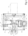
- the first x-ray tube assembly to be described includes an anode A and a cathode assembly B.
- An evacuated envelope C is evacuated such that an electron beam 10 can pass from a cathode cup 12 to a focal spot 14 on an annular face 16 of the anode.
- a rotational driver D rotates the anode A and the evacuated envelope C while a magnetic susceptor assembly E holds the cathode assembly B stationary.
- the anode A is beveled adjacent its annular peripheral edge to define the anode surface 16 which is bombarded by the electron beam 10 to generate a beam 18 of x-rays.
- the entire anode may be machined from a single piece of tungsten.
- the focal spot path along the anode surface may be defined by an annular strip of tungsten which is connected to a highly thermally conductive disk or plate.
- the anode and envelope are immersed in an oil-based dielectric fluid which is circulated to a cooling means. In order to keep the face 16 of the anode cool, portions of the anode between the cooling fluid are highly thermally conductive.
- the anode assembly A forms one end of the vacuum envelope C.
- a ceramic cylinder 20 is connected between the anode and an opposite or cathode end plate 22.
- the end plate 22 includes a collar 24 defining a circumferential aperture therein.
- At least an annular portion of the cylinder 20 closely adjacent to the anode is x-ray transparent to provide a window from which the x-ray beam 18 is emitted.
- the cylinder 20 is constructed at least in part of a dielectric material such that the high voltage differential is maintained between the anode A and the end plate 22.
- the end plate is biased to the potential of the cathode assembly B, generally about 100-200 kV more negative than the anode A.
- the cathode assembly B includes a cathode hub 30 which is rotatably mounted by a bearing 32 relative to the cathode plate 22.
- the cathode cup 12 is mounted on a peripheral extension of the cathode hub.
- the cathode cup 12 includes a filament or other source of electrons.
- the cathode cup, specifically the filament, is electrically connected with a filament drive transformer assembly 34.
- An exterior transformer winding 34a is connected with a filament power supply which controls the amount of current passing through the cathode filament, and hence controls the thermionic emission.
- a stationary transformer winding 34b is mounted directly across the ceramic envelope wall 20 in a magnetically coupled relationship therewith.
- the interior transformer winding 34b is electrically connected across the cathode filament.
- a plurality of cathode cups or filaments may be provided.
- the additional cathode cups may be used for producing different types of electron beams, such as beams with a broader or narrower focal spot, higher or lower energy beams, or the like.
- additional cathode cups may function as a back up in case the first cup should fail or burn out.
- An externally controllable electronic switching circuit (not shown) can be provided between the internal transformer winding 34b and the cathode cups to enable selection of which cathode cup receives the power from the transformer.
- Other means may also be used for transferring power to the filament such as a capacitive coupling or an annular transformer that is disposed adjacent the susceptor assembly E.
- cathode bearing shaft 36 is also shown.
- the shaft 36 is received in the collar 24 and receivingly connects to bearing 32.
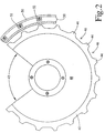
- the magnetic susceptor assembly E includes a susceptor 40 which follows the cylindrical inner surface of the envelope.
- the cylindrical contour of the susceptor may be broken out or discontinuous to accommodate other structures within the x-ray tube.
- the susceptor has an arc segment 42 removed in order to accommodate the filament transformer 34.
- the susceptor has alternating teeth or projections 44 and valleys or recesses 46.
- the susceptor is mounted on a lever arm means such a disk portion 48 which holds the teeth portions of a magnetic susceptor at the maximum possible lever arm radius permitted by the envelope 20.
- the susceptor portion is constructed of a material with high magnetic susceptibility even at the elevated temperatures found in an x-ray tube.
- a keeper or other frame structure 50 is rigidly mounted around the exterior of the envelope.
- a plurality of magnets 52 preferably high strength permanent magnets, are positioned opposite each of the magnetic susceptor teeth portions. Due to the higher operating temperatures associated with x-ray tubes, the magnets are constructed of a material with a high curie temperature, such as A1nico 8, neodymium-iron-boron, samarium-cobalt, or other high temperature permanent magnets.
- the magnets 52 are mounted to the keeper 50 such that adjacent magnets have opposite polarity faces disposed towards the magnetic susceptor 40. This causes magnetic flux paths to be formed through the magnetic susceptor between adjacent magnets.
- an adjustment assembly 60 and a flexible member, or bellows, 62 adjust concentricity of the axes of the hub 30 and the envelope 20.
- the bellows 62 connects the cathode end plate 22, i.e., collar 24, to the shaft 36 that has a bore in which the bearing 32 is mounted.
- the bellows maintains the vacuum in the envelope C by providing a flexible vacuum seal between the end plate 22 and the shaft 36. While the shaft 36 is received by the collar 24, and may well fit snugly, a vacuum seal between these components is not assured.
- the bellows 62 is connected between the end plate 22 and the shaft 36 to provide a flexible vacuum tight seal therebetween.
- the adjustment assembly 60 includes a cylindrical portion 64 which is integrally or fixedly connected with the end plate 22. One or more screws 66 extend through the cylindrical portion into contact with the shaft 36 to prevent the shaft from moving axially and provide pivot points.
- An eccentric ring 68 is rotatably received between the cylindrical portion 64 and the shaft 36. The shaft 36 is received off center in the ring 68 such that rotating the ring 68 rotates the axis of shaft 36 eccentrically.
- Adjustment screws 70 selectively fix the rotational position of the eccentric ring 68 when the shaft central axis and a central axis of the cylinder 20 are angularly aligned.
- the set screws 66 adjust the relative position of the axes and the eccentric ring 68 and adjustment screws 70 adjust the relative or angular orientation of the axes.
- the eccentric ring 68 may be eliminated in favor of three adjustment screws 70. Adjusting the adjustment and set screws 70 and 66 together shifts the relative position of the axes. Adjusting the adjustment and set screws 70 and 66 to different degrees adjusts the relative orientation (and usually position) of the axes.
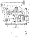
- An adjustment assembly 80 includes adjustment screws 84, an annular ring eccentric 86, and an anode extension 88.
- a bellows 82 is an annular flexible member which connects the cylinder 20 to the ring 86 which, in turn is connected with a vacuum tight connection to the anode extension to maintain the vacuum in the envelope C.
- the eccentric ring 86 is rotated to adjust the relative position of the cylinder 20 to the anode A to adjust or realign their axes.
- the adjustment assembly 80 which adjusts the relative position of the axes of the anode and the cylinder 20 can be used in combination with the adjustment assembly 60 which adjusts the relative position and orientation of the axes of the cylinder 20 and the hub 30.
- bearing 90 is provided to stabilize a shaft 94 which is rigidly connected to the anode A.
- the bearing allows rotation of the shaft 94 and the anode about a central axis of the shaft 96.
- the bearing 92 is likewise disposed on the shaft 36 to provide stability and rotation.
- the bearings 90 and 92 are received in an outer housing 98 or other associated structure.
- Adjustment screws 70 or other adjustment structures are again provided to adjust the position and orientation of the central axes of the shafts 36, 94, hence of the cathode hub and the anode.
- a flexible bellows 100 facilitates maintenance of the vacuum state in the envelope C. Due to its flexible nature, the bellows allows for adjustment of the constituent elements of the x-ray tube.
- An external x-ray transparent plate or cylindrical sector 102 is disposed externally of the x-ray tube.
- the plates can be rendered x-ray transparent by removing a slot sized to pass the beam.
- An AC voltage is pressed upon plate 102 to attract or repel the beam 18 according to desired positioning of the beam.
- Rotational position information, generated using position markers 104 on the anode A, is monitored by a position encoder 106 to assure proper timing.
- An internal plate or cylinder 108 is insulated from the target and operates in conjunction with the external plate 102 to attract or repel the beam.
- a control circuit 110 adjusts the potential across the external plate 102 and the internal plate 108 in accordance with the angular position of the anode to control the focal spot and remove unwanted focal spot motion.
- the cathode is utilized to provide this function.
- an internal structure, such as plate 108, is not necessary to control the focal spot motion.
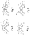
- FIGURES 7 and 8 illustrate two configurations providing side-to-side correction of the focal spot position.
- the internal and external plate pair primarily achieve a radial adjustment.
- a pair of external electrodes 112, 114 positioned leading and trailing the focal spot are oppositely charged to attract and repel the beam. This pushes and pulls the beam with radial and circumferential positional adjustments.
- an offset external plate 102 and a rotating, symmetric internal structure 108 provide radial and circumferential positioning.
- the internal structure attracts or repels the focal spot generally along a vector through the focal spot, i.e., radially.
- the vector through the center of the external plate and the focal spot has both radial and circumferential components.
- the invention is also realized by manipulating magnetic fields, as opposed to electrostatic fields. Suitable magnets are used in place of electrostatic plates in such an arrangement.
Landscapes
- Health & Medical Sciences (AREA)
- General Health & Medical Sciences (AREA)
- Toxicology (AREA)
- X-Ray Techniques (AREA)
Applications Claiming Priority (3)
| Application Number | Priority Date | Filing Date | Title |
|---|---|---|---|
| US345921 | 1994-11-28 | ||
| US08/345,921 US5581591A (en) | 1992-01-06 | 1994-11-28 | Focal spot motion control for rotating housing and anode/stationary cathode X-ray tubes |
| EP95307599A EP0715333B1 (fr) | 1994-11-28 | 1995-10-25 | Assemblage de tubes à rayons X |
Related Parent Applications (1)
| Application Number | Title | Priority Date | Filing Date |
|---|---|---|---|
| EP95307599A Division EP0715333B1 (fr) | 1994-11-28 | 1995-10-25 | Assemblage de tubes à rayons X |
Publications (2)
| Publication Number | Publication Date |
|---|---|
| EP1087419A2 true EP1087419A2 (fr) | 2001-03-28 |
| EP1087419A3 EP1087419A3 (fr) | 2004-01-07 |
Family
ID=23357104
Family Applications (2)
| Application Number | Title | Priority Date | Filing Date |
|---|---|---|---|
| EP00122847A Withdrawn EP1087419A3 (fr) | 1994-11-28 | 1995-10-25 | Assemblage de tubes à rayons X |
| EP95307599A Expired - Lifetime EP0715333B1 (fr) | 1994-11-28 | 1995-10-25 | Assemblage de tubes à rayons X |
Family Applications After (1)
| Application Number | Title | Priority Date | Filing Date |
|---|---|---|---|
| EP95307599A Expired - Lifetime EP0715333B1 (fr) | 1994-11-28 | 1995-10-25 | Assemblage de tubes à rayons X |
Country Status (4)
| Country | Link |
|---|---|
| US (1) | US5581591A (fr) |
| EP (2) | EP1087419A3 (fr) |
| JP (1) | JPH08222395A (fr) |
| DE (1) | DE69521108T2 (fr) |
Cited By (4)
| Publication number | Priority date | Publication date | Assignee | Title |
|---|---|---|---|---|
| FR2829286A1 (fr) * | 2001-09-03 | 2003-03-07 | Ge Med Sys Global Tech Co Llc | Dispositif et procede d'emission de rayons x |
| WO2010067260A1 (fr) * | 2008-12-08 | 2010-06-17 | Philips Intellectual Property & Standards Gmbh | Compensation d’une oscillation anodique pour des tubes à rayons x du type à anode rotative |
| CN103413744A (zh) * | 2013-07-22 | 2013-11-27 | 西北核技术研究所 | 一种串级式电子束二极管 |
| CN109887821A (zh) * | 2018-09-28 | 2019-06-14 | 胡逸民 | 双靶面阳极x射线球管 |
Families Citing this family (24)
| Publication number | Priority date | Publication date | Assignee | Title |
|---|---|---|---|---|
| DE19639920C2 (de) * | 1996-09-27 | 1999-08-26 | Siemens Ag | Röntgenröhre mit variablem Fokus |
| US6164820A (en) * | 1998-05-06 | 2000-12-26 | Siemens Aktiengesellschaft | X-ray examination system particulary for computed tomography and mammography |
| US6570960B1 (en) | 2000-03-07 | 2003-05-27 | Koninklijke Philips Electronics N.V. | High voltage isolated rotor drive for rotating anode x-ray tube |
| FR2809278B1 (fr) | 2000-05-19 | 2002-07-19 | Ge Med Sys Global Tech Co Llc | Dispositif d'emission de rayons x et procede de montage |
| FR2809277B1 (fr) | 2000-05-19 | 2002-08-23 | Ge Med Sys Global Tech Co Llc | Dispositif d'emission de rayons x et procede de montage |
| US6480572B2 (en) | 2001-03-09 | 2002-11-12 | Koninklijke Philips Electronics N.V. | Dual filament, electrostatically controlled focal spot for x-ray tubes |
| US7382856B2 (en) * | 2001-12-04 | 2008-06-03 | X-Ray Optical Systems, Inc. | X-ray source assembly having enhanced output stability, and fluid stream analysis applications thereof |
| ATE476088T1 (de) * | 2001-12-04 | 2010-08-15 | X Ray Optical Sys Inc | Röntgenquelle mit verbesserter strahlstabilität und ihre anwendung in der analyse von strömenden flüssigkeiten |
| AU2003268462A1 (en) * | 2002-09-03 | 2004-03-29 | Parker Medical, Inc. | Multiple grooved x-ray generator |
| DE10301071A1 (de) * | 2003-01-14 | 2004-07-22 | Siemens Ag | Vorrichtung und Verfahren zum Einstellen der Brennfleckposition einer Röntgenröhre |
| WO2004079752A2 (fr) * | 2003-03-04 | 2004-09-16 | Inpho, Inc. | Systemes et procedes pour la commande d'une source de rayons x |
| JP2007501503A (ja) * | 2003-08-04 | 2007-01-25 | エックス−レイ オプティカル システムズ インコーポレーテッド | 管電力調節および遠隔較正を使用して出力安定性が向上したx線源アセンブリ |
| US6944270B1 (en) * | 2004-02-26 | 2005-09-13 | Osmic, Inc. | X-ray source |
| DE102005049273B4 (de) * | 2005-10-14 | 2011-06-01 | Siemens Ag | Drehkolbenröhre |
| JP4908341B2 (ja) * | 2006-09-29 | 2012-04-04 | 株式会社東芝 | 回転陽極型x線管装置 |
| CN101965623A (zh) * | 2008-03-11 | 2011-02-02 | 皇家飞利浦电子股份有限公司 | 圆形层析摄影合成x射线管 |
| US9480440B2 (en) * | 2011-09-28 | 2016-11-01 | Qr Srl | System and method for cone beam computed tomography |
| DE102013107736A1 (de) * | 2013-07-19 | 2015-01-22 | Ge Sensing & Inspection Technologies Gmbh | Röntgenprüfvorrichtung für die Materialprüfung und Verfahren zur Erzeugung hochaufgelöster Projektionen eines Prüflings mittels Röntgenstrahlen |
| EP3204959B1 (fr) | 2014-10-06 | 2018-11-21 | Koninklijke Philips N.V. | Agencement de modification pour un dispositif de génération de rayons x |
| DE102015220754B3 (de) * | 2015-10-23 | 2017-02-09 | Siemens Healthcare Gmbh | Verfahren und Messeinrichtung zur Ermittlung des Elektrodenabstands von Röntgenröhren |
| CN110275471B (zh) * | 2019-07-17 | 2020-12-04 | 郑州信大先进技术研究院 | 基于ni运动控制卡的桌面型工业ct运动控制系统 |
| US11665806B2 (en) * | 2019-12-20 | 2023-05-30 | Schlumberger Technology Corporation | Beam alignment systems and method |
| EP3933881A1 (fr) | 2020-06-30 | 2022-01-05 | VEC Imaging GmbH & Co. KG | Source de rayons x à plusieurs réseaux |
| US12230468B2 (en) | 2022-06-30 | 2025-02-18 | Varex Imaging Corporation | X-ray system with field emitters and arc protection |
Family Cites Families (16)
| Publication number | Priority date | Publication date | Assignee | Title |
|---|---|---|---|---|
| US2111412A (en) | 1928-12-08 | 1938-03-15 | Gen Electric | X-ray apparatus |
| US2926270A (en) * | 1957-12-30 | 1960-02-23 | Gen Electric | Rotating anode x-ray tube |
| US3714487A (en) * | 1970-03-26 | 1973-01-30 | Philips Corp | X-ray tube having external means to align electrodes |
| US3646379A (en) * | 1970-05-18 | 1972-02-29 | Machlett Lab Inc | X-ray tube having controllable focal spot size |
| US3689790A (en) * | 1971-04-29 | 1972-09-05 | Pepi Inc | Moving target sealed x-ray tube |
| DE3401749A1 (de) * | 1984-01-19 | 1985-08-01 | Siemens AG, 1000 Berlin und 8000 München | Roentgendiagnostikeinrichtung mit einer roentgenroehre |
| FR2566987B1 (fr) * | 1984-06-29 | 1986-10-10 | Thomson Cgr | Dispositif radiologique a asservissement en position de foyer |
| JP2539193B2 (ja) | 1984-12-20 | 1996-10-02 | バリアン・アソシエイツ・インコーポレイテッド | 高強度x線源 |
| JPS61153934A (ja) * | 1984-12-27 | 1986-07-12 | Toshiba Corp | 焦点位置可変形x線管 |
| DE3542127A1 (de) * | 1985-11-28 | 1987-06-04 | Siemens Ag | Roentgenstrahler |
| US4878235A (en) * | 1988-02-25 | 1989-10-31 | Varian Associates, Inc. | High intensity x-ray source using bellows |
| US4993055A (en) * | 1988-11-23 | 1991-02-12 | Imatron, Inc. | Rotating X-ray tube with external bearings |
| IL91119A0 (en) * | 1989-07-26 | 1990-03-19 | Elscint Ltd | Arrangement for controlling focal spot position in x-ray tubes |
| DE4004013A1 (de) | 1990-02-09 | 1991-08-14 | Siemens Ag | Roentgen-drehroehre |
| US5200985A (en) * | 1992-01-06 | 1993-04-06 | Picker International, Inc. | X-ray tube with capacitively coupled filament drive |
| US5384820A (en) * | 1992-01-06 | 1995-01-24 | Picker International, Inc. | Journal bearing and radiation shield for rotating housing and anode/stationary cathode X-ray tubes |
-
1994
- 1994-11-28 US US08/345,921 patent/US5581591A/en not_active Expired - Fee Related
-
1995
- 1995-10-25 DE DE69521108T patent/DE69521108T2/de not_active Expired - Fee Related
- 1995-10-25 EP EP00122847A patent/EP1087419A3/fr not_active Withdrawn
- 1995-10-25 EP EP95307599A patent/EP0715333B1/fr not_active Expired - Lifetime
- 1995-11-16 JP JP7322393A patent/JPH08222395A/ja not_active Withdrawn
Cited By (7)
| Publication number | Priority date | Publication date | Assignee | Title |
|---|---|---|---|---|
| FR2829286A1 (fr) * | 2001-09-03 | 2003-03-07 | Ge Med Sys Global Tech Co Llc | Dispositif et procede d'emission de rayons x |
| US6879662B2 (en) | 2001-09-03 | 2005-04-12 | Ge Medical Systems Global Technology Company, Llc | Radiation emission device and method |
| WO2010067260A1 (fr) * | 2008-12-08 | 2010-06-17 | Philips Intellectual Property & Standards Gmbh | Compensation d’une oscillation anodique pour des tubes à rayons x du type à anode rotative |
| CN103413744A (zh) * | 2013-07-22 | 2013-11-27 | 西北核技术研究所 | 一种串级式电子束二极管 |
| CN103413744B (zh) * | 2013-07-22 | 2016-03-09 | 西北核技术研究所 | 一种串级式电子束二极管 |
| CN109887821A (zh) * | 2018-09-28 | 2019-06-14 | 胡逸民 | 双靶面阳极x射线球管 |
| CN109887821B (zh) * | 2018-09-28 | 2021-06-04 | 胡逸民 | 双靶面阳极x射线球管 |
Also Published As
| Publication number | Publication date |
|---|---|
| DE69521108D1 (de) | 2001-07-05 |
| US5581591A (en) | 1996-12-03 |
| JPH08222395A (ja) | 1996-08-30 |
| EP1087419A3 (fr) | 2004-01-07 |
| DE69521108T2 (de) | 2001-11-15 |
| EP0715333B1 (fr) | 2001-05-30 |
| EP0715333A1 (fr) | 1996-06-05 |
Similar Documents
| Publication | Publication Date | Title |
|---|---|---|
| EP0715333B1 (fr) | Assemblage de tubes à rayons X | |
| EP0601717B1 (fr) | Support de cathode avec suscepteur magnétique | |
| US5268955A (en) | Ring tube x-ray source | |
| US5438605A (en) | Ring tube x-ray source with active vacuum pumping | |
| US5105456A (en) | High duty-cycle x-ray tube | |
| US4788705A (en) | High-intensity X-ray source | |
| US4674109A (en) | Rotating anode x-ray tube device | |
| EP0473852A1 (fr) | Tube à rayons X tournant avec des paliers externes | |
| US5384820A (en) | Journal bearing and radiation shield for rotating housing and anode/stationary cathode X-ray tubes | |
| US4821305A (en) | Photoelectric X-ray tube | |
| EP0330336B1 (fr) | Source de rayons X à haute intensité avec un soufflet | |
| JP2004265602A (ja) | X線装置 | |
| JP4298826B2 (ja) | ストラドルベアリングアセンブリー | |
| US6570960B1 (en) | High voltage isolated rotor drive for rotating anode x-ray tube | |
| US7515687B2 (en) | Compact source with very bright X-ray beam | |
| JP4309290B2 (ja) | X線ターゲット用液体金属ヒートパイプ構造 | |
| EP0377534A1 (fr) | Dispositif de tube à rayons X | |
| JP3030069B2 (ja) | X線管 | |
| US8379798B2 (en) | Moving high flux X-ray target and assembly | |
| WO1987006055A1 (fr) | Tube photoelectrique a rayons-x | |
| JP2021044226A (ja) | X線管 | |
| JP2004063171A (ja) | 回転陽極x線管装置 | |
| RU2168791C1 (ru) | Рентгеновская трубка | |
| JPH05128983A (ja) | 回転体への給電装置 |
Legal Events
| Date | Code | Title | Description |
|---|---|---|---|
| PUAI | Public reference made under article 153(3) epc to a published international application that has entered the european phase |
Free format text: ORIGINAL CODE: 0009012 |
|
| AC | Divisional application: reference to earlier application |
Ref document number: 715333 Country of ref document: EP |
|
| AK | Designated contracting states |
Kind code of ref document: A2 Designated state(s): DE FR GB NL |
|
| RAP1 | Party data changed (applicant data changed or rights of an application transferred) |
Owner name: PHILIPS MEDICAL SYSTEMS (CLEVELAND), INC. |
|
| PUAL | Search report despatched |
Free format text: ORIGINAL CODE: 0009013 |
|
| RAP1 | Party data changed (applicant data changed or rights of an application transferred) |
Owner name: KONINKLIJKE PHILIPS ELECTRONICS N.V. |
|
| AK | Designated contracting states |
Kind code of ref document: A3 Designated state(s): DE FR GB NL |
|
| 17P | Request for examination filed |
Effective date: 20040707 |
|
| AKX | Designation fees paid |
Designated state(s): DE FR GB NL |
|
| 17Q | First examination report despatched |
Effective date: 20041215 |
|
| STAA | Information on the status of an ep patent application or granted ep patent |
Free format text: STATUS: THE APPLICATION IS DEEMED TO BE WITHDRAWN |
|
| 18D | Application deemed to be withdrawn |
Effective date: 20080501 |