EP1087642A2 - Procédé pour commander des sources lumineuses dans des automobiles, et dispositif pour la mise en oeuvre dudit procédé - Google Patents
Procédé pour commander des sources lumineuses dans des automobiles, et dispositif pour la mise en oeuvre dudit procédé Download PDFInfo
- Publication number
- EP1087642A2 EP1087642A2 EP00120491A EP00120491A EP1087642A2 EP 1087642 A2 EP1087642 A2 EP 1087642A2 EP 00120491 A EP00120491 A EP 00120491A EP 00120491 A EP00120491 A EP 00120491A EP 1087642 A2 EP1087642 A2 EP 1087642A2
- Authority
- EP
- European Patent Office
- Prior art keywords
- lamps
- signal
- light
- microprocessor
- current
- Prior art date
- Legal status (The legal status is an assumption and is not a legal conclusion. Google has not performed a legal analysis and makes no representation as to the accuracy of the status listed.)
- Withdrawn
Links
- 238000000034 method Methods 0.000 title claims description 11
- 230000009131 signaling function Effects 0.000 claims description 13
- 230000006870 function Effects 0.000 description 9
- 230000001419 dependent effect Effects 0.000 description 3
- 238000005286 illumination Methods 0.000 description 2
- 230000002411 adverse Effects 0.000 description 1
- 238000010586 diagram Methods 0.000 description 1
- 230000003760 hair shine Effects 0.000 description 1
- 238000004519 manufacturing process Methods 0.000 description 1
Images

Classifications
-
- B—PERFORMING OPERATIONS; TRANSPORTING
- B60—VEHICLES IN GENERAL
- B60Q—ARRANGEMENT OF SIGNALLING OR LIGHTING DEVICES, THE MOUNTING OR SUPPORTING THEREOF OR CIRCUITS THEREFOR, FOR VEHICLES IN GENERAL
- B60Q1/00—Arrangement of optical signalling or lighting devices, the mounting or supporting thereof or circuits therefor
- B60Q1/26—Arrangement of optical signalling or lighting devices, the mounting or supporting thereof or circuits therefor the devices being primarily intended to indicate the vehicle, or parts thereof, or to give signals, to other traffic
- B60Q1/2607—Arrangement of optical signalling or lighting devices, the mounting or supporting thereof or circuits therefor the devices being primarily intended to indicate the vehicle, or parts thereof, or to give signals, to other traffic comprising at least two indicating lamps
-
- B—PERFORMING OPERATIONS; TRANSPORTING
- B60—VEHICLES IN GENERAL
- B60Q—ARRANGEMENT OF SIGNALLING OR LIGHTING DEVICES, THE MOUNTING OR SUPPORTING THEREOF OR CIRCUITS THEREFOR, FOR VEHICLES IN GENERAL
- B60Q1/00—Arrangement of optical signalling or lighting devices, the mounting or supporting thereof or circuits therefor
- B60Q1/02—Arrangement of optical signalling or lighting devices, the mounting or supporting thereof or circuits therefor the devices being primarily intended to illuminate the way ahead or to illuminate other areas of way or environments
- B60Q1/04—Arrangement of optical signalling or lighting devices, the mounting or supporting thereof or circuits therefor the devices being primarily intended to illuminate the way ahead or to illuminate other areas of way or environments the devices being headlights
- B60Q1/14—Arrangement of optical signalling or lighting devices, the mounting or supporting thereof or circuits therefor the devices being primarily intended to illuminate the way ahead or to illuminate other areas of way or environments the devices being headlights having dimming means
- B60Q1/1407—General lighting circuits comprising dimming circuits
-
- H—ELECTRICITY
- H05—ELECTRIC TECHNIQUES NOT OTHERWISE PROVIDED FOR
- H05B—ELECTRIC HEATING; ELECTRIC LIGHT SOURCES NOT OTHERWISE PROVIDED FOR; CIRCUIT ARRANGEMENTS FOR ELECTRIC LIGHT SOURCES, IN GENERAL
- H05B45/00—Circuit arrangements for operating light-emitting diodes [LED]
- H05B45/10—Controlling the intensity of the light
-
- Y—GENERAL TAGGING OF NEW TECHNOLOGICAL DEVELOPMENTS; GENERAL TAGGING OF CROSS-SECTIONAL TECHNOLOGIES SPANNING OVER SEVERAL SECTIONS OF THE IPC; TECHNICAL SUBJECTS COVERED BY FORMER USPC CROSS-REFERENCE ART COLLECTIONS [XRACs] AND DIGESTS
- Y02—TECHNOLOGIES OR APPLICATIONS FOR MITIGATION OR ADAPTATION AGAINST CLIMATE CHANGE
- Y02B—CLIMATE CHANGE MITIGATION TECHNOLOGIES RELATED TO BUILDINGS, e.g. HOUSING, HOUSE APPLIANCES OR RELATED END-USER APPLICATIONS
- Y02B20/00—Energy efficient lighting technologies, e.g. halogen lamps or gas discharge lamps
- Y02B20/30—Semiconductor lamps, e.g. solid state lamps [SSL] light emitting diodes [LED] or organic LED [OLED]
Definitions
- the invention relates to a method for controlling lamps of vehicles, preferably of motor vehicles, according to The preamble of claim 1 and a device for carrying it out of such a method according to the preamble of the claim 5.
- the lamps assign different signal functions.
- the rear lights usually have a tail light, a brake light, a rear fog light and a reversing light on.
- the intended ones To form illuminants by means of LEDs with low current, for example 20% of the nominal current and less. In this area the LEDs have strong tolerances in the forward voltage. This means that the LEDs light up differently, depending on Manufacturing tolerances.
- the invention has for its object the generic method and to design the generic device so that the Brightness of the illuminant can be set specifically.
- the lamps are clocked with nominal current and their brightness through pulse width modulation in accordance with legal requirements set.
- the lamps are advantageously LEDs but also be incandescent.
- the pulse width modulated signals are generated in the microprocessor and the respective driver stages Bulbs supplied.
- the change in brightness is made by the pulse-width modulated signal, which in the microprocessor with a corresponding program is generated.
- the illuminants LEDs they can be reliably controlled with low current that they are legal according to the respective signal function have the prescribed brightness.
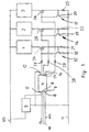
- the circuit is used to control various signal functions a rear light of a motor vehicle.
- the circuit can also for controlling lamps in the interior of the vehicle can be used, for example for dashboard lighting, reading lamps and the same. It is essential that the signal functions can be controlled with different brightness levels.
- the illuminants 1 to are advantageous 3 light fields, each formed by LEDs.
- the illuminant 1 can, for example, a tail light, the illuminant 2 Brake light and the illuminant 3 a rear fog light of a rear light of a motor vehicle.
- a microprocessor 4 controls the Brightness of the lamps 1 to 3 with an appropriate program depending on the input signals 5 to 8.
- the microprocessor 4 is with a ROM memory and a corresponding one Program.
- the microprocessor 4 is preceded by a Voltage regulator 9, the battery voltage 10 of for example 12 volts down to 5 volts.
- the voltage regulator 9 is present Mass 11 on.
- the voltage regulator 9 specifies the input signal 5 the microprocessor 4.
- the analog input signals 6 to 8 for the Illuminants 1 to 3 are the microprocessor 4 according to the Program stored in the ROM memory edited and are on Output 12 to 14 of the microprocessor 4 on.
- Current limiter stages 15 are connected downstream of the microprocessor 4 to 17, which limit the current flowing to the lamps 1 to 3, preferably to a constant current.
- the current limiter stages 15 to 17 are of the same design and each have a transistor 18 to 20 and one lying parallel to them Resistor 21 to 23.
- each lamp 1 to 3 24 to 26 there is a driver stage for controlling each lamp 1 to 3 24 to 26 are provided, each having at least one electronic Switches, preferably a MOSFET, have. That to the Outputs 12 to 14 of the microprocessor 4 each pending Output signal Is via a resistor 27 to 29 each corresponding driver stage 24 to 26 supplied.
- a driver stage for controlling each lamp 1 to 3 24 to 26 each having at least one electronic Switches, preferably a MOSFET, have. That to the Outputs 12 to 14 of the microprocessor 4 each pending Output signal Is via a resistor 27 to 29 each corresponding driver stage 24 to 26 supplied.
- the lamps 1 to 3 are advantageously formed by LED fields. These LED or signal fields must be in relation to their respective Function certain legal requirements regarding Luminous intensity, area dimension and distance of the individual functional fields from each other. Depending on the required signal combination different illumination variants are created. They can also Signal fields 1 to 3 can be assigned several signal functions. As a result, the signal fields 1 to 3 must be dependent on the required Signal combination have different levels of brightness. 5 shows possible combinations for four Signal fields 1 to 3 and 30 specified. These signal fields will be formed by LED fields and are in the rear light of a motor vehicle intended. The signal fields 1 to 3, 30 can, as in 5 is shown schematically, close to each other, so that the individual signal fields on the rear light when not switched on Rear light does not appear as different fields. In the example, it is assumed that the rear light has functions a tail light SL, a brake light BR and a rear fog light NSL should have.
- the tail light SL lights up on the rear light.
- the lights on the rear light Brake light BR on. 5 in the exemplary embodiment in this case also all four signal fields 1 to 3, 30 energized, see above that they light up at the same time.
- the brake light BR is that it shines with a minimum brightness, is in the embodiment assume that the brightness of the signal fields 1 to 3, 30 has level 2.
- Fig. 5 shows the further case that the rear light of the motor vehicle is switched on and the brake is actuated. Will the If brake is not applied, signal fields 1 to 3, 30 light up with Level 1. As soon as the brake pedal is also pressed, the Brightness of fields 1 to 3, 30 raised to level 2, i.e. the Luminosity is increased so that in relation to the brake light prescribed brightness values are generated.
- the driver also switches on the rear fog light is switched on, then the signal field in the example 30 very high in brightness to level 3.
- the signal field 30 thus has the function of the rear fog lamp.
- the Signal fields 1 to 3 remain at the same level in terms of brightness 1, so that these three signal fields the function of the tail light fulfill.
- the case is indicated that the tail light SL and the rear fog light NSL are switched on and the brake pedal is actuated so that the brake light BR lights up.
- the brightness of signal field 1 is increased to level 3, so that this signal field 1 fulfills the function of the brake light.
- the brightness of signal fields 2 and 3 remains at level 1, so that these signal fields have the function of the tail light SL.
- the signal field 30 serves as a rear fog lamp NSL and has accordingly the high brightness with level 3.
- the changes in brightness are made by a pulse width modulated Signal generated by the program stored in the microprocessor 4 becomes. So that on-board voltage fluctuations have no influence the maximum current level in the current path to the light fields 1 to 3, 30, the current in this path will be described using the Current limiter stages 15 to 17 limited.
- the LEDs of the signal fields 1 to 3, 30 are clocked with nominal current, while the brightness is controlled by the pulse pause ratio.
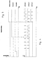
- Fig. 3 shows the dependence of the input signals on the time for the Rear fog light NSL, brake light BR and tail light SL. It it can be seen that for the tail light SL the smallest input signal is provided. For the brake light BR and the rear fog light NSL higher input signals are provided, the input signal for the rear fog light NSL is higher than for the brake light BR.
- Fig. 3 shows the case in which the tail light is first switched on becomes. Then the brake pedal is operated, which causes the Brake light comes on. Finally, the rear fog light NSL switched on. Once the appropriate functions are turned on the corresponding input signal becomes corresponding elevated.
- Fig. 4 shows an example of the corresponding for the three signal fields 1 to 3 clocked currents and those for setting the required Brightness provided pulse width modulated signals. How 1 results from the signal field 1, the tail light SL, the Signal field 2 the brake light BR and signal field 3 the rear fog light NSL assigned. If only the tail light SL is switched on, then the brightness of the corresponding LEDs can be proportionate be small. As has been explained with reference to FIG. 5, in this case, all signal fields with the same low Brightness activated. As soon as the brake pedal is pressed and accordingly the brake light BR is switched on, by appropriate Change in the pulse width modulated signal reached, that the signal fields assigned to the brake light function accordingly shine brightly.
- the pulse pause ratio of the LEDs associated with the tail light SL and the brake light BR has the same pulse-pause ratio like the signal field 2 assigned to the brake light BR.
- the signal field 1, which is assigned to the tail light SL, has a smaller pulse-pause ratio than signal fields 2 and 3.
- the program stored in the microprocessor 4 can be dependent the required signal function of the rear light corresponding pulse pause ratios or the pulse width modulated Generate signals for the individual signal fields.
- the microprocessor 4 receives the corresponding connections 6 to 8 Signals when the tail light SL and the rear fog light NSL switched on and the brake pedal operated. To the Outputs 12 to 14 are then through the microprocessor 4th processed output signals with which the corresponding Signal fields 1 to 3, 30 are controlled.
- the law on the rear lights of motor vehicles Requirements regarding the luminous intensity, the area dimension and the distance between the individual functional areas are flawless Fulfills.
- the signal fields 1 to 3, 30 can have multiple signal functions be occupied.
- the signal field 1 as tail light SL and as Brake light BR used.
- the signal field 30 come depending on the signal combination Function of a tail light SL, a brake light BR and one Rear fog light NSL too.
- the signal fields become dependent of the respective signal combination, with different brightness levels controlled.
- the spatial division of the individual Light signal functions is variable depending on the particular Signal combination.
- the distance between the brake light BR and the Rear fog light NSL can easily be 100 mm, as the Legislator prescribes.
- the LEDs of signal fields 1 to 3, 30 are only slightly energized, about 20% of the nominal current and less, point in this current range the LEDs usually have strength tolerances in the forward voltage which causes the LEDs in this area to shine differently brightly, so that the respective functional field would be unevenly illuminated.
- the LEDs are clocked at nominal current and the brightness This peculiarity is controlled by the pulse pause ratio the LEDs are not noticeably not noticeable when the current is low.
- the rear light of the rear light can also be used Functional area can be built into the device.
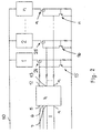
- the number can range from 1 to n, depending on the number the desired signal functions.
- the microprocessor 4 has in this case a corresponding number of inputs 5 to n and Outputs 12 to n on.
- the battery voltage 10 is usually 12 volts and is by the voltage regulator 9 (Fig. 1) on the dimension necessary for the operation of the microprocessor 4 is reduced.
- the Signal fields 1 to n are the current limiter stages 15 to n and Driver levels 24 to n assigned.
- each signal field can also have at least one Incandescent lamp be formed, which is controlled in the same way as the LEDs becomes. It is possible to have several signal fields Assign incandescent lamps.
- the signal fields 1 to 3, 30 described must be in the rear light not be spatially separated areas. So they can LEDs assigned to these signal fields on a common circuit board sit, the necessary for the respective signal function LEDs are controlled in the manner described.
- the rear light has the lens in a known manner, accordingly is colored in the required functional areas.
- the LEDs on the Circuit board are arranged behind the lens so that in operation of the vehicle light up the corresponding lens areas.
Landscapes
- Engineering & Computer Science (AREA)
- Mechanical Engineering (AREA)
- Lighting Device Outwards From Vehicle And Optical Signal (AREA)
- Arrangements Of Lighting Devices For Vehicle Interiors, Mounting And Supporting Thereof, Circuits Therefore (AREA)
Applications Claiming Priority (2)
| Application Number | Priority Date | Filing Date | Title |
|---|---|---|---|
| DE19945546 | 1999-09-23 | ||
| DE19945546A DE19945546B4 (de) | 1999-09-23 | 1999-09-23 | Verfahren zur Ansteuerung von Leuchtmitteln von Fahrzeugen, vorzugsweise von Kraftfahrzeugen, sowie Vorrichtung zur Durchführung des Verfahrens |
Publications (2)
| Publication Number | Publication Date |
|---|---|
| EP1087642A2 true EP1087642A2 (fr) | 2001-03-28 |
| EP1087642A3 EP1087642A3 (fr) | 2004-07-21 |
Family
ID=7922988
Family Applications (1)
| Application Number | Title | Priority Date | Filing Date |
|---|---|---|---|
| EP00120491A Withdrawn EP1087642A3 (fr) | 1999-09-23 | 2000-09-20 | Procédé pour commander des sources lumineuses dans des automobiles, et dispositif pour la mise en oeuvre dudit procédé |
Country Status (3)
| Country | Link |
|---|---|
| US (1) | US6414437B1 (fr) |
| EP (1) | EP1087642A3 (fr) |
| DE (1) | DE19945546B4 (fr) |
Cited By (5)
| Publication number | Priority date | Publication date | Assignee | Title |
|---|---|---|---|---|
| EP1985496A2 (fr) | 2007-04-26 | 2008-10-29 | odelo GmbH | Procédé et circuit destinés à la commande de moyens d'éclairage durant un processus de mesure photométrique |
| WO2009006963A1 (fr) * | 2007-07-07 | 2009-01-15 | Bayerische Motoren Werke Aktiengesellschaft | Système d'éclairage pour véhicule automobile |
| DE102009034918A1 (de) * | 2009-07-28 | 2011-02-03 | GM Global Technology Operations, Inc., Detroit | Beleuchtungsvorrichtung für ein Kraftfahrzeug |
| EP2549836A1 (fr) * | 2011-07-21 | 2013-01-23 | Valeo Vision | Circuit de commande d'un dispositif de signalisation ou d'éclairage à double fonction et procédé de commande correspondant |
| EP2650174A3 (fr) * | 2012-04-14 | 2018-04-04 | Volkswagen Ag | Procédé destiné à la commande d'un dispositif d'éclairage et système d'éclairage |
Families Citing this family (48)
| Publication number | Priority date | Publication date | Assignee | Title |
|---|---|---|---|---|
| DE19945775B4 (de) * | 1999-09-24 | 2005-05-25 | Audi Ag | Leuchtenanordnung als Heckleuchte für ein Kraftfahrzeug |
| DE10027478A1 (de) * | 2000-06-02 | 2001-12-06 | Hella Kg Hueck & Co | Beleuchtungseinrichtung für ein Kraftfahrzeug |
| US6720871B2 (en) * | 2000-12-20 | 2004-04-13 | Transalert, Inc. | Modulated intensity flasher for vehicle brake light with lockout |
| DE10143792B4 (de) * | 2001-09-06 | 2004-11-11 | Aspöck Systems GmbH | Fahrzeugrückleuchte |
| DE10147268A1 (de) * | 2001-09-26 | 2003-04-24 | Kastriot Merlaku | Rückwärtslicht-Scheinwerfer für das Fahrzeug mit Leuchtdioden |
| US6717373B2 (en) * | 2002-01-07 | 2004-04-06 | Leica Microsystems Inc. | Method and apparatus for supplying power to a source of illumination in a microscope |
| US6853587B2 (en) * | 2002-06-21 | 2005-02-08 | Micron Technology, Inc. | Vertical NROM having a storage density of 1 bit per 1F2 |
| DE10236301A1 (de) * | 2002-08-08 | 2004-02-19 | Hella Kg Hueck & Co. | Schaltungsanordnung zur schnellen Ansteuerung und Überwachung elektrischer Beleuchtungseinrichtungen in Anhängerfahrzeugen |
| DE10236304A1 (de) * | 2002-08-08 | 2004-02-19 | Hella Kg Hueck & Co. | Schaltungsanordnung zur Ansteuerung und Überwachung elektrischer Beleuchtungseinrichtungen in Anhängefahrzeugen |
| DE10236302A1 (de) * | 2002-08-08 | 2004-02-19 | Hella Kg Hueck & Co. | Schaltungsanordnung und ein durch die Schaltungsanordnung auszuführendes Verfahren zur Ansteuerung und Überwachung elektrischer Beleuchtungseinrichtungen in Anhängerfahrzeugen |
| DE10247677A1 (de) * | 2002-10-12 | 2004-04-22 | Hella Kg Hueck & Co. | Ansteuerung für mindestens eine Leuchtdiode an einem Kraftfahrzeug |
| DE10313246A1 (de) * | 2003-03-25 | 2004-10-21 | Sitronic Gesellschaft für elektrotechnische Ausrüstung mbH. & Co. KG | Kraftfahrzeugleuchtenmodul |
| DE10323521A1 (de) * | 2003-05-24 | 2004-12-23 | Adam Opel Ag | Scheinwerfer für ein Kraftfahrzeug und Nebelscheinwerfer sowie Steuereinrichtung zur Ansteuerung von Leuchtmitteln eines Scheinwerfers und/oder eines Nebelscheinwerfers |
| US7071633B2 (en) * | 2003-07-10 | 2006-07-04 | Trafcon Industries, Inc. | Burst pulse circuit for signal lights and method |
| DE102004029629A1 (de) * | 2004-06-18 | 2006-01-05 | Adam Opel Ag | Parklicht an einem Kraftfahrzeug |
| EP1774834A1 (fr) * | 2004-07-23 | 2007-04-18 | Magna International Inc | Systeme d'alimentation et procede pour systemes d'eclairage d'automobile par del |
| DE102004036137B4 (de) * | 2004-07-26 | 2019-03-28 | Volkswagen Ag | Steuerungsvorrichtung für eine Beleuchtungseinrichtung eines Fahrzeugs und Verfahren zum Steuern einer solchen Beleuchtungseinrichtung |
| DE102004047547A1 (de) * | 2004-09-30 | 2006-04-06 | Daimlerchrysler Ag | Heckleuchte |
| DE102004050655A1 (de) | 2004-10-18 | 2006-06-01 | Volkswagen Ag | Fahrzeug-Beleuchtungsvorrichtung und Verfahren zum Steuern einer Fahrzeug-Beleuchtungsvorrichtung |
| DE102005032921B4 (de) * | 2005-07-14 | 2007-03-08 | Daimlerchrysler Ag | Beleuchtungsvorrichtung für ein Fahrzeug |
| DE102005035813A1 (de) * | 2005-07-27 | 2007-02-01 | Conti Temic Microelectronic Gmbh | Verfahren und Vorrichtung zur Visualisierung der Bremskraft eines Kraftfahrzeuges |
| DE102006026738B4 (de) * | 2006-06-08 | 2020-03-12 | Continental Automotive Gmbh | Verfahren und Steuersystem zur Steuerung der Leuchtleistung zumindest einer Leuchte in einem Fahrzeug |
| DE102006035503A1 (de) * | 2006-07-31 | 2008-02-07 | Dr.Ing.H.C. F. Porsche Ag | Heckleuchte für ein Fahrzeug |
| DE102006037342B4 (de) * | 2006-08-08 | 2013-07-18 | Johnson Controls Automotive Electronics Gmbh | Schaltung für ein Kraftfahrzeug, insbesondere zur Ansteuerung einer Beleuchtungseinrichtung |
| DE102006055610A1 (de) * | 2006-11-24 | 2008-05-29 | Hella Kgaa Hueck & Co. | Verfahren zur gepulsten Bestromung von Glühlampen in Kraftfahrzeugen |
| DE102007002809A1 (de) | 2007-01-18 | 2008-07-24 | Hella Kgaa Hueck & Co. | Verfahren zum gepulsten Betrieb einer Beleuchtungseinrichtung mit Leuchtdioden (LED) für Kraftfahrzeuge |
| DE202007007532U1 (de) * | 2007-05-26 | 2008-10-09 | Hella Kgaa Hueck & Co. | Elektrische Schaltung für Leuchtdioden |
| DE102007032523A1 (de) * | 2007-07-12 | 2009-01-15 | Volkswagen Ag | Verfahren und Vorrichtung zum Steuern einer Beleuchtungseinrichtung für ein Fahrzeug zum Bereitstellen eines Parklichts |
| DE102007044936B4 (de) * | 2007-09-20 | 2011-08-11 | Continental Automotive GmbH, 30165 | Fahrzeuglichtanlage |
| US20090122565A1 (en) * | 2007-11-13 | 2009-05-14 | Lear Corporation | Vehicle exterior lighting system |
| DE102008027148A1 (de) * | 2008-06-03 | 2009-12-10 | Technisat Digital Gmbh | Verfahren zum Betrieb einer Lichtquelle eines Kraftfahrzeugs |
| EP2200403B1 (fr) | 2008-10-29 | 2010-08-25 | Quan Mei Technology Co. Ltd | Dispositif luminescent à régulation de courant pour véhicule |
| DE102009025346A1 (de) | 2009-06-18 | 2010-12-23 | Volkswagen Ag | Verfahren zum Einstellen mehrerer Beleuchtungsvorrichtungen eines Fahrzeugs und Beleuchtungssystem für ein Fahrzeug |
| DE102009053418A1 (de) * | 2009-11-19 | 2011-05-26 | Hella Kgaa Hueck & Co. | Beleuchtungsvorrichtung und Schaltungsverfahren für Kraftfahrzeuge sowie Signalleuchte |
| DE102010047376A1 (de) | 2010-10-05 | 2012-04-05 | Gm Global Technology Operations Llc (N.D.Ges.D. Staates Delaware) | Kraftfahrzeug-Scheinwerfer |
| US8723427B2 (en) | 2011-04-05 | 2014-05-13 | Abl Ip Holding Llc | Systems and methods for LED control using on-board intelligence |
| DE102011051152A1 (de) * | 2011-06-17 | 2012-12-20 | Hella Kgaa Hueck & Co. | Verfahren zum Betrieb einer Leuchte sowie Leuchte für ein Fahrzeug |
| US8823265B2 (en) * | 2011-06-22 | 2014-09-02 | Osram Sylvania Inc. | Sequential vehicle signaling system and method |
| FR2997602B1 (fr) | 2012-10-26 | 2017-09-15 | Valeo Illuminacion | Dispositif de connexion electrique d'un projecteur |
| JP5835503B2 (ja) * | 2012-12-13 | 2015-12-24 | 日産自動車株式会社 | 車室内照明装置 |
| DE102016107725B4 (de) * | 2016-04-26 | 2023-09-28 | Dr. Ing. H.C. F. Porsche Aktiengesellschaft | Verfahren zum Ansteuern einer Mehrzahl von Leuchtmodulen eines Matrixscheinwerfers für ein Kraftfahrzeug |
| US10894509B2 (en) | 2016-07-19 | 2021-01-19 | Alpine 4 Technologies, Ltd | Universal brake light control mechanism |
| US10807513B2 (en) | 2016-10-15 | 2020-10-20 | Alpine 4 Technologies, Ltd | Microprocessor controlled rechargeable brake light control circuit |
| DE102017222461A1 (de) * | 2016-12-22 | 2018-06-28 | Autosystems America Inc. | Konstantstrom-leistungstreiberschaltung für eine automobilleuchtenbaugruppe |
| DE102017206818A1 (de) | 2017-04-24 | 2018-10-25 | Volkswagen Aktiengesellschaft | Fahrstufenanzeige-Ausleuchteinheit |
| FR3078383A1 (fr) | 2018-02-27 | 2019-08-30 | Valeo Vision | Module lumineux pour un vehicule automobile comprenant une pluralite de branches de sources lumineuses |
| DE102020131463A1 (de) * | 2020-11-27 | 2022-06-02 | evotron GmbH & Co. KG | Anordnung zum Betreiben von segmentierten Ringbeleuchtungen oder segmentierten Drei- oder Vierseitenbeleuchtungen |
| US11592154B2 (en) * | 2021-07-12 | 2023-02-28 | Texas Instruments Incorporated | Methods and apparatus for multi-segment illumination of spatial light modulators |
Citations (5)
| Publication number | Priority date | Publication date | Assignee | Title |
|---|---|---|---|---|
| GB2139340A (en) * | 1983-04-30 | 1984-11-07 | Bosch Gmbh Robert | Light for motor vehicles |
| DE3916875A1 (de) * | 1989-05-24 | 1990-12-06 | Ullmann Ulo Werk | Signalleuchte, insbesondere mehrkammersignalleuchte fuer kraftfahrzeuge |
| WO1997048134A1 (fr) * | 1996-06-13 | 1997-12-18 | Gentex Corporation | Ensemble d'eclairage comportant des diodes electroluminescentes |
| WO1999010867A1 (fr) * | 1997-08-26 | 1999-03-04 | Color Kinetics Incorporated | Procede et dispositif pour eclairage multicolore a diodes electroluminescentes |
| DE19753096A1 (de) * | 1997-11-29 | 1999-06-02 | Volkswagen Ag | Kraftfahrzeugleuchte |
Family Cites Families (14)
| Publication number | Priority date | Publication date | Assignee | Title |
|---|---|---|---|---|
| DE3714421C2 (de) * | 1987-04-30 | 1993-10-28 | Audi Ag | Schaltungsanordnung für Anzeigeleuchten in Kraftfahrzeugen |
| US5001398A (en) * | 1989-07-03 | 1991-03-19 | Motorola, Inc. | Lamp intensity control system having over-current protection |
| DE4120893C2 (de) * | 1991-06-25 | 2000-06-15 | Bayerische Motoren Werke Ag | Beleuchtungsvorrichtung für Kraftfahrzeuge |
| JP2597346Y2 (ja) * | 1993-02-01 | 1999-07-05 | アルプス電気株式会社 | ランプ調光装置 |
| US5877897A (en) * | 1993-02-26 | 1999-03-02 | Donnelly Corporation | Automatic rearview mirror, vehicle lighting control and vehicle interior monitoring system using a photosensor array |
| US5381074A (en) * | 1993-06-01 | 1995-01-10 | Chrysler Corporation | Self calibrating lighting control system |
| FR2711884B1 (fr) * | 1993-10-29 | 1996-01-05 | Solartec Sarl | Dispositif de signalisation notamment pour la signalisation routière, aéronautique ou maritime. |
| US5765940A (en) * | 1995-10-31 | 1998-06-16 | Dialight Corporation | LED-illuminated stop/tail lamp assembly |
| JPH09207660A (ja) * | 1996-02-01 | 1997-08-12 | Harness Sogo Gijutsu Kenkyusho:Kk | 自動車用リアランプ制御回路 |
| DE19732828C2 (de) * | 1997-07-30 | 2001-01-18 | Siemens Ag | Schaltungsanordnung zur Ansteuerung eines Leuchtdioden-Arrays |
| DE19734750C2 (de) * | 1997-08-12 | 2003-04-30 | Reitter & Schefenacker Gmbh | Heckleuchte von Kraftfahrzeugen |
| DE19804891A1 (de) * | 1998-02-07 | 1999-09-02 | Mannesmann Vdo Ag | Schaltungsanordnung zur Beleuchtung einer Anzeigevorrichtung in einem Kraftfahrzeug mit Leuchtdioden |
| EP1006506A1 (fr) * | 1998-12-03 | 2000-06-07 | Hewlett-Packard Company | Affichage optique pour véhicule |
| DE19930174A1 (de) * | 1999-06-30 | 2001-01-04 | Patent Treuhand Ges Fuer Elektrische Gluehlampen Mbh | Ansteuerschaltung für LED und zugehöriges Betriebsverfahren |
-
1999
- 1999-09-23 DE DE19945546A patent/DE19945546B4/de not_active Expired - Fee Related
-
2000
- 2000-09-20 EP EP00120491A patent/EP1087642A3/fr not_active Withdrawn
- 2000-09-22 US US09/668,646 patent/US6414437B1/en not_active Expired - Lifetime
Patent Citations (5)
| Publication number | Priority date | Publication date | Assignee | Title |
|---|---|---|---|---|
| GB2139340A (en) * | 1983-04-30 | 1984-11-07 | Bosch Gmbh Robert | Light for motor vehicles |
| DE3916875A1 (de) * | 1989-05-24 | 1990-12-06 | Ullmann Ulo Werk | Signalleuchte, insbesondere mehrkammersignalleuchte fuer kraftfahrzeuge |
| WO1997048134A1 (fr) * | 1996-06-13 | 1997-12-18 | Gentex Corporation | Ensemble d'eclairage comportant des diodes electroluminescentes |
| WO1999010867A1 (fr) * | 1997-08-26 | 1999-03-04 | Color Kinetics Incorporated | Procede et dispositif pour eclairage multicolore a diodes electroluminescentes |
| DE19753096A1 (de) * | 1997-11-29 | 1999-06-02 | Volkswagen Ag | Kraftfahrzeugleuchte |
Cited By (8)
| Publication number | Priority date | Publication date | Assignee | Title |
|---|---|---|---|---|
| EP1985496A2 (fr) | 2007-04-26 | 2008-10-29 | odelo GmbH | Procédé et circuit destinés à la commande de moyens d'éclairage durant un processus de mesure photométrique |
| EP1985496A3 (fr) * | 2007-04-26 | 2009-07-22 | odelo GmbH | Procédé et circuit destinés à la commande de moyens d'éclairage durant un processus de mesure photométrique |
| WO2009006963A1 (fr) * | 2007-07-07 | 2009-01-15 | Bayerische Motoren Werke Aktiengesellschaft | Système d'éclairage pour véhicule automobile |
| DE102009034918A1 (de) * | 2009-07-28 | 2011-02-03 | GM Global Technology Operations, Inc., Detroit | Beleuchtungsvorrichtung für ein Kraftfahrzeug |
| EP2549836A1 (fr) * | 2011-07-21 | 2013-01-23 | Valeo Vision | Circuit de commande d'un dispositif de signalisation ou d'éclairage à double fonction et procédé de commande correspondant |
| FR2978093A1 (fr) * | 2011-07-21 | 2013-01-25 | Valeo Vision | Circuit de commande d'un dispositif de signalisation ou d'eclairage a double fonction et procede de commande correspondant |
| US9096173B2 (en) | 2011-07-21 | 2015-08-04 | Valeo Vision | Control circuit for a dual-function signaling or lighting device and corresponding control method |
| EP2650174A3 (fr) * | 2012-04-14 | 2018-04-04 | Volkswagen Ag | Procédé destiné à la commande d'un dispositif d'éclairage et système d'éclairage |
Also Published As
| Publication number | Publication date |
|---|---|
| DE19945546B4 (de) | 2005-06-23 |
| DE19945546A1 (de) | 2001-04-05 |
| US6414437B1 (en) | 2002-07-02 |
| EP1087642A3 (fr) | 2004-07-21 |
Similar Documents
| Publication | Publication Date | Title |
|---|---|---|
| DE19945546B4 (de) | Verfahren zur Ansteuerung von Leuchtmitteln von Fahrzeugen, vorzugsweise von Kraftfahrzeugen, sowie Vorrichtung zur Durchführung des Verfahrens | |
| EP2161494B1 (fr) | Dispositif d'éclairage pour un véhicule automobile | |
| DE102005007626B4 (de) | Fahrzeugscheinwerfer | |
| EP1648204B1 (fr) | Appareil d'éclairage pour un véhicule et procédé pour controler un appareil d'éclairage pour un véhicule | |
| DE102016114744A1 (de) | Beleuchtete Plakette für ein Fahrzeug | |
| EP2039224A1 (fr) | Circuit de commande électrique d'un phare de véhicule à moteur | |
| DE19945775B4 (de) | Leuchtenanordnung als Heckleuchte für ein Kraftfahrzeug | |
| DE10011843A1 (de) | Kraftfahrzeugleuchte | |
| DE202016106347U1 (de) | Beleuchtete Plakette für ein Fahrzeug | |
| DE102012203206A1 (de) | Beleuchtungseinrichtung und Verfahren zum Wechseln von Farbausgaben | |
| DE4308514A1 (de) | Fahrzeugscheinwerfer-Steuersystem | |
| DE102016206275A1 (de) | Verfahren zum Betreiben wenigstens einer Beleuchtungsvorrichtung eines stillstehenden Kraftfahrzeugs | |
| DE102004003698B4 (de) | Schaltungsanordnung zur Ansteuerung von Leuchtmitteln | |
| DE202013011958U1 (de) | Dynamisches Tagfahrlicht | |
| DE102004022718A1 (de) | Verfahren zur Ansteuerung einer Blinkleuchte für Kraftfahrzeuge | |
| EP1558063A1 (fr) | Méthode et dispositif pour commander au moins un dispositif d'éclairage | |
| EP3466756B1 (fr) | Conduit de lumière en cascade pouvant être animé | |
| EP2088833B1 (fr) | Procédé destiné au fonctionnement d'un dispositif d'éclairage à Leds de véhicule automobile | |
| DE3714421A1 (de) | Schaltungsanordnung fuer anzeigeleuchten in kraftfahrzeugen | |
| DE102017213987B4 (de) | Verfahren zum Betreiben einer Beleuchtungseinrichtung in einem Kraftfahrzeug; sowie Kraftfahrzeug | |
| DE69935423T2 (de) | Signalisierungsleuchte einer fahrzeugsverzögerung mit konstantem lichtstrom | |
| EP3442312A1 (fr) | Procédé d'éclairage d'un espace intérieur d'un véhicule automobile ainsi que vehicule automobile | |
| DE19813595A1 (de) | Vorrichtung zur Blinkersteuerung in einem Kraftfahrzeug | |
| DE102004036137B4 (de) | Steuerungsvorrichtung für eine Beleuchtungseinrichtung eines Fahrzeugs und Verfahren zum Steuern einer solchen Beleuchtungseinrichtung | |
| DE4434274A1 (de) | Beleuchtungsanordnung mit in Reihe geschalteten Leuchtdioden |
Legal Events
| Date | Code | Title | Description |
|---|---|---|---|
| PUAI | Public reference made under article 153(3) epc to a published international application that has entered the european phase |
Free format text: ORIGINAL CODE: 0009012 |
|
| AK | Designated contracting states |
Kind code of ref document: A2 Designated state(s): AT BE CH CY DE DK ES FI FR GB GR IE IT LI LU MC NL PT SE |
|
| AX | Request for extension of the european patent |
Free format text: AL;LT;LV;MK;RO;SI |
|
| PUAL | Search report despatched |
Free format text: ORIGINAL CODE: 0009013 |
|
| AK | Designated contracting states |
Kind code of ref document: A3 Designated state(s): AT BE CH CY DE DK ES FI FR GB GR IE IT LI LU MC NL PT SE |
|
| AX | Request for extension of the european patent |
Extension state: AL LT LV MK RO SI |
|
| 17P | Request for examination filed |
Effective date: 20041210 |
|
| AKX | Designation fees paid |
Designated state(s): DE FR GB IT |
|
| 17Q | First examination report despatched |
Effective date: 20050419 |
|
| 17Q | First examination report despatched |
Effective date: 20050419 |
|
| RAP1 | Party data changed (applicant data changed or rights of an application transferred) |
Owner name: ODELO GMBH |
|
| STAA | Information on the status of an ep patent application or granted ep patent |
Free format text: STATUS: THE APPLICATION IS DEEMED TO BE WITHDRAWN |
|
| 18D | Application deemed to be withdrawn |
Effective date: 20100209 |