EP1088708A2 - Luftsackvorrichtung - Google Patents
Luftsackvorrichtung Download PDFInfo
- Publication number
- EP1088708A2 EP1088708A2 EP00121022A EP00121022A EP1088708A2 EP 1088708 A2 EP1088708 A2 EP 1088708A2 EP 00121022 A EP00121022 A EP 00121022A EP 00121022 A EP00121022 A EP 00121022A EP 1088708 A2 EP1088708 A2 EP 1088708A2
- Authority
- EP
- European Patent Office
- Prior art keywords
- air bag
- sewed
- fabric
- gas
- inflater
- Prior art date
- Legal status (The legal status is an assumption and is not a legal conclusion. Google has not performed a legal analysis and makes no representation as to the accuracy of the status listed.)
- Granted
Links
- 239000004744 fabric Substances 0.000 claims abstract description 87
- 230000002093 peripheral effect Effects 0.000 claims abstract description 18
- 238000004891 communication Methods 0.000 claims abstract description 5
- 230000008961 swelling Effects 0.000 claims description 6
- 239000002759 woven fabric Substances 0.000 description 5
- 239000004677 Nylon Substances 0.000 description 2
- 239000002184 metal Substances 0.000 description 2
- 238000012986 modification Methods 0.000 description 2
- 230000004048 modification Effects 0.000 description 2
- 229920001778 nylon Polymers 0.000 description 2
- 238000010276 construction Methods 0.000 description 1
- 238000007599 discharging Methods 0.000 description 1
- 230000000694 effects Effects 0.000 description 1
- 238000000034 method Methods 0.000 description 1
- 239000002991 molded plastic Substances 0.000 description 1
- 230000000452 restraining effect Effects 0.000 description 1
Images


Classifications
-
- B—PERFORMING OPERATIONS; TRANSPORTING
- B60—VEHICLES IN GENERAL
- B60R—VEHICLES, VEHICLE FITTINGS, OR VEHICLE PARTS, NOT OTHERWISE PROVIDED FOR
- B60R21/00—Arrangements or fittings on vehicles for protecting or preventing injuries to occupants or pedestrians in case of accidents or other traffic risks
- B60R21/02—Occupant safety arrangements or fittings, e.g. crash pads
- B60R21/16—Inflatable occupant restraints or confinements designed to inflate upon impact or impending impact, e.g. air bags
- B60R21/23—Inflatable members
- B60R21/231—Inflatable members characterised by their shape, construction or spatial configuration
- B60R21/233—Inflatable members characterised by their shape, construction or spatial configuration comprising a plurality of individual compartments; comprising two or more bag-like members, one within the other
-
- B—PERFORMING OPERATIONS; TRANSPORTING
- B60—VEHICLES IN GENERAL
- B60R—VEHICLES, VEHICLE FITTINGS, OR VEHICLE PARTS, NOT OTHERWISE PROVIDED FOR
- B60R21/00—Arrangements or fittings on vehicles for protecting or preventing injuries to occupants or pedestrians in case of accidents or other traffic risks
- B60R21/02—Occupant safety arrangements or fittings, e.g. crash pads
- B60R21/16—Inflatable occupant restraints or confinements designed to inflate upon impact or impending impact, e.g. air bags
- B60R21/23—Inflatable members
- B60R21/231—Inflatable members characterised by their shape, construction or spatial configuration
- B60R21/2334—Expansion control features
- B60R21/2346—Soft diffusers
-
- B—PERFORMING OPERATIONS; TRANSPORTING
- B60—VEHICLES IN GENERAL
- B60R—VEHICLES, VEHICLE FITTINGS, OR VEHICLE PARTS, NOT OTHERWISE PROVIDED FOR
- B60R21/00—Arrangements or fittings on vehicles for protecting or preventing injuries to occupants or pedestrians in case of accidents or other traffic risks
- B60R21/02—Occupant safety arrangements or fittings, e.g. crash pads
- B60R21/16—Inflatable occupant restraints or confinements designed to inflate upon impact or impending impact, e.g. air bags
- B60R21/20—Arrangements for storing inflatable members in their non-use or deflated condition; Arrangement or mounting of air bag modules or components
- B60R21/203—Arrangements for storing inflatable members in their non-use or deflated condition; Arrangement or mounting of air bag modules or components in steering wheels or steering columns
-
- B—PERFORMING OPERATIONS; TRANSPORTING
- B60—VEHICLES IN GENERAL
- B60R—VEHICLES, VEHICLE FITTINGS, OR VEHICLE PARTS, NOT OTHERWISE PROVIDED FOR
- B60R21/00—Arrangements or fittings on vehicles for protecting or preventing injuries to occupants or pedestrians in case of accidents or other traffic risks
- B60R21/02—Occupant safety arrangements or fittings, e.g. crash pads
- B60R21/16—Inflatable occupant restraints or confinements designed to inflate upon impact or impending impact, e.g. air bags
- B60R21/23—Inflatable members
- B60R21/239—Inflatable members characterised by their venting means
Definitions
- the present invention relates in general to a passenger restraining device of a motor vehicle, and more particular to an air bag device mounted on a steering wheel for protecting a driver.
- Some of the air bags are of a type for a driver, that is mounted on a boss potion of a steering wheel. Upon a vehicle collision, gas is rushed into the air bag to instantly expand the same thereby to safely hold the upper half of the driver.
- Some of the air bags are of a type that comprises front and rear circular woven fabrics of Nylon (trade name) whose peripheries are sewed together. Thus, when applied with no gas, the air bag is shaped flat.
- the front fabric that faces the boss portion of the steering wheel is formed with a gas inlet opening, and a peripheral portion of the gas inlet opening is fixed to the boss portion of the steering wheel.
- An inflater is also mounted on the boss portion, which has a gas outlet connected to the gas inlet opening of the air bag.
- the air bag is kept folded small and housed in a container mounted on the boss portion.
- a certain amount of gas is instantly ejected from the inflater to expand the air bag.
- the air bag breaks the container and gets out of the same and safely holds the upper half of the driver.
- Japanese Patent First Provisional Publication 7-149199 proposes a measure that forces the air bag to expand laterally flat.
- a so-called gas guide fabric is installed in the air bag, by which the gas is guided to flow laterally outward. More specifically, within the air bag, there is installed a circular inner fabric as the gas guide fabric, that is arranged to cover over the gas inlet opening and has a peripheral portion sewed on spaced portions of the front circular woven fabric of the air bag. Upon gas generation, the gas is forced to flow through the sewed spaced portions.
- vent openings are provided in the front circular woven fabric around the periphery of the circular inner fabric.
- the air bag device of the above-mentioned publication has failed to give users satisfaction. That is, due to its inherent construction, a larger amount of gas is discharged through the vent openings without contributing to expansion of the air bag. This brings about a need of increasing capacity and size of the inflater and lowering the air bag expansion speed. If, for solving this drawback, the vent openings are positioned away from the gas inlet opening, that is, near the periphery of the front circular woven fabric, a new drawback tends to occur. That is, in this case, at a final stage of the air bag expansion, the hot gas discharged from the vent openings may be directed toward the upper half of the driver. Thus, to cool the gas, additional measure becomes needed.
- an air bag device comprising first and second fabrics having peripheral portions sewed together to constitute a bag structure; a gas inlet opening formed in the first fabric; a third fabric smaller in size than the first and second fabrics, the third fabric being installed in the bag structure in a manner to cover over the gas inlet opening; a plurality of sewed points by which the first and third fabrics are sewed together; a plurality of gas flow passages provided between the first and third fabrics, each gas flow passage being defined between neighboring two of the sewed points; and a vent opening that extends through at least one of the sewed points to provide a communication between a major portion of the interior of the bag structure and the outside of the same.
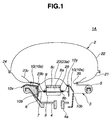
- FIGs. 1 and 2 there is shown an air bag device 1A of a first embodiment of the present invention.
- the air bag device 1A shown in these drawings shows an expanded condition of the air bag.
- a cover member 10 shown is in a broken condition.
- the air bag device 1A is mounted on a boss portion 4 of a steering wheel 3 for protecting a driver D (see Fig. 3D) upon a vehicle collision.
- the steering wheel 3 is connected to an upper end of a steering shaft which is inclined with respect to a vehicle floor.
- the steering wheel 3 generally comprises the boss portion 4 which is connected to the steering shaft, an annular grip or rim portion 5 which extends around the boss portion 4 and a plurality of spokes 6 which extend between the boss portion and the rim portion 5.
- the boss portion 4 has a socket portion 4a in which the upper end of the steering shaft is intimately and tightly put.
- the air bag device 1A comprises an air bag 2 for protecting the driver D, a base plate 7 for supporting the air bag 2, an inflater 8 for producing gas, a retainer 9 for retaining the inflater 8 on the base plate 7 and a cover member 10 for covering the air bag 2 in a folded condition.
- the cover member 10 shown in this drawing has been already broken due to expansion of the air bag 2.
- the base plate 7 is produced by pressing a metal plate.
- the base plate 7 comprises a rectangular major portion and four side walls that project downward from four sides of the major portion.
- the major portion is formed with a circular opening for putting therein the inflater 8.
- a plurality of bolt holes (not shown) are formed in the major portion around the circular opening.
- the side walls of the base plate 7 are provided with connecting pieces that are connected to a core metal of the boss portion 4.
- the inflater 8 comprises a cylinder body 8a which is put in the circular opening of the base plate 7 and an annular flange 8b which extends around the cylinder body 8a.
- the cylinder body 8a has therearound a plurality of gas ejection openings 8c. As shown, these gas ejection openings 8c are positioned above the flange 8b.
- the annular flange 8b is formed with a plurality of bolt holes which are mated with the bolt holes of the base plate 7.
- the retainer 9 comprises an annular plate and a plurality of bolts which extend downward from the annular plate.
- the annular flange of the inflater 8 is put on the peripheral portion of the circular opening of the base plate 7 and position adjustment is so made that the bolt openings of the annular flange are mated with the corresponding bolt openings of the base plate 7 respectively. Then, the annular retainer 9 is put on the annular flange of the inflater 8 having the bolts inserted through the mated bolt openings respectively, and then, nuts (not shown) are tightly engaged with the bolts.
- the base plate 7, the inflater 8 and the retainer 9 constitute an integrated unit which is fixed to the boss portion 4 of the steering wheel 3.
- the cover member 10 is made of a molded plastic, and comprises a convex center portion 10a which covers the integrated unit, and a wall portion 10b which surrounds the integrated unit. As is understood from Fig. 1, the wall portion 10b is secured to the side walls of the base plate 7. For this securing, a retainer belt extending along the side walls of the base plate 7 and bolts and nuts are used. If desired, rivets may be used in place of the bolts and nuts.
- the convex center portion 10a of the cover member 10 is formed at its inner surface with a groove or tear line that is easily broken when pressed by the air bag 2 upon expansion of the same.
- Fig. 1 that shows the expanded condition of the air bag 2 denoted by 10x and 10y are the portions where the tear line has been present.
- the air bag 2 generally comprises a first circular fabric 21 which faces the steering wheel 3, a second circular fabric 22 which faces the interior of the vehicle and a smaller diameter third circular fabric 23 which is sewed on an inner surface of the first circular fabric 21.
- These three fabrics 21, 22 and 23 are woven fabrics of Nylon (trade name) and they are concentric with one another when properly assembled.
- peripheral portions 24 of the first and second circular fabrics 21 and 22 are sewed together.
- the air bag 2 is shaped flat.
- the first circular fabric 21 is formed at its center portion with a gas inlet opening 28 into which an upper part of the inflater 8 is projected.
- the gas ejection openings 8c of the inflater 8 are exposed to the interior of the air bag 2.
- a peripheral portion of the gas inlet opening 28 is tightly put between the flange of the inflater 8 and the annular retainer 9.
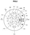
- the third circular fabric 23 serves as a gas guide means, and is smaller in size than the first and second circular fabrics 21 and 22.
- the diameter of the third circular fabric 23 is slightly larger than 1/2 of that of the first circular fabric 21.
- the third circular fabric 23 comprises a center portion 23a which covers over the upper end of the inflater 8, an annular intermediate portion 23b which is sewed on the inner surface of the first circular fabric 21 and a peripheral portion 23c which is free from the first circular fabric 21.
- annular intermediate portion 23b is sewed on the first circular fabric 21 by four circular points S-1, S-2, S-3 and S-4 which are arranged at equally spaced intervals in a manner to surround the inflater 8.
- each sewed circular point S-1, S-2, S-3 or S-4 is provided by making a double stitching on a circular portion, so that the space defined in the circular point is sealed from the surrounding.
- the circular point S-4 is formed with a vent opening 35 through which the interior of the air bag 2 is communicated with the outside of the same. It is to be noted that the vent opening 35 is not exposed to the gas flow passages P-3 and P-4, but exposed to the major portion of the interior of the air bag 2. In other words, the vent opening 35 is provided at a remote position from the gas ejection openings 8c of the inflater 8 with respect to a gas flow passage defined in the air bag 2.
- vent openings 35 may be provided in some of the circular points S-1, S-2, S-3 and S-4. Tests have revealed that the best result is obtained when the number of the vent openings 35 is two.
- the annular retainer 9 is put into the space between the first and third circular fabrics 21 and 23, and the bolts of the retainer 9 are inserted through the mated bolt openings of the flange of the inflater 8 and the base plate 7 having the peripheral portion of the gas inlet opening 28 of the first circular fabric 21 put between the retainer 9 and the flange of the inflater 8. Then, the nuts are engaged with the bolts for providing a unit that includes the air bag 2, the base plate 7, the inflater 8 and the retainer 9. Then, the air bag is folded into a small size and the cover member 10 is secured to the base plate 7 in a manner to cover the folded air bag 2.
- the unit with the cover member 10 is mounted to the boss portion 4 of the steering wheel 3 in the above-mentioned manner.
- the inflater 8 Upon a vehicle collision, the inflater 8 is energized to eject a certain amount of gas from the gas ejection openings 8c. Thus, the air bag 2 is instantly expanded to protect the driver D (see Fig. 3D). At an initial stage of the expansion, the cover member 10 is broken to allow full expansion of the air bag 2 instantly.
- the gas is forced to change its traveling direction near the peripheral portion of the air bag 2. This change in traveling direction causes the peripheral portion of the air bag 2 to expand.
- expansion of the air bag 2 is carried out stepwise. That is, before the full expansion, the air bag 2 can take such a half-expanded condition as shown in Fig. 3B. This is very effective to protect a driver D who has been seated out of position with his or her upper half positioned very close to the steering wheel 3. That is, such expansion manner is very effective for safely receiving the driver D.
- the expansion speed of the air bag 2 can be easily controlled or adjusted by only changing the number or size of the sewed points S-1, S-2, S-3 and S-4. Due to this change, the size of each gas flow passage P-1, P-2, P-3 or P-4 is changed.
- the fabric 22 can expand largely in an axial direction, which increases the driver protecting ability of the air bag 2.
- vent opening 35 Since the vent opening 35 is provided at a remote position from the gas ejection openings 8c of the inflater 8, the gas from the gas ejection openings 8c is effectively used for expanding the air bag 2. If the vent opening 35 is positioned near the gas ejection openings 8c, remarked loss of air tends to occur.
- the inflater 8 Due to provision of the third circular fabric 23, relatively long travelling passages for the gas are provided in the air bag 2. Thus, the high temperature gas from the inflater 8 can be sufficiently cooled during traveling in the passages until it is discharged through the vent opening 35. This means that a low cost type can be used as the inflater 8.
- the usage does not bring about substantial drawbacks on the size and weight of the air bag 2 and the easiness with which the air bag 2 is folded. Furthermore, for the same reason, the cost of the air bag device 1A can be reduced.
- vent opening 35 is provided in the circular point S-4 that serves to connect the first and third circular fabrics 21 and 23, compact and simplified structure of the air bag 2 is obtained.
- gas flow passages P-1, P-2, P-3 and P-4 defined between the first and third circular fabrics 21 and 23 have each a convexly curved entrance (see Fig. 2), gas flow into the passages P-1, P-2, P-3 and P-4 is smoothly carried out, which brings about a speedy and assured expansion of the air bag 2.
- FIG. 4 there is shown an air bag device 1B of a second embodiment of the present invention.
- a measure is further employed wherein a maximally swelled part "MAX" of the center portion 23a of the third circular fabric 23 is controlled below an imaginary plane "V" that is defined by an upper surface of the rim portion 5 of the steering wheel 3.
- This measure is embodied by changing or adjusting the position of the sewed circular points S-1, S-2, S-3 and S-4. With this measure, the driver D who has been seated with his or her upper half positioned very close to the steering wheel 3 is much safely protected by the air bag 2.
- FIG. 5 there is shown an air bag device 1C of a third embodiment of the present invention.
- the top of the center portion 23a of the third circular fabric 23 is fixed to the top of the inflater 8 by means of a connector 51.
- this connector 51 substantially same effect as that of the above-mentioned second embodiment 1B is obtained. That is, the swelling of the center portion 23a of the third circular fabric 23 is restricted not to extend beyond the imaginary plane "V".
- FIG. 6 and 7 there is shown an air bag device 1D of a fourth embodiment of the present invention.
- annular baffle plate 55 is employed, which is arranged to surround the inflater 8. As is well seen from Fig. 7, the baffle plate 55 is formed with gas guide slots 55a through which the gas from the inflater 8 is guided to the gas flow passages P-1, P-2, P-3 and P-4. With this baffle plate 55, the gas flow toward the gas flow passages is rectified.
- FIG. 8 there is shown an air bag device 1E of a fifth embodiment of the present invention.
- the sewed peripheral portions 24 of the air bag 2 are placed inside of the air bag 2.
- FIGs. 9 and 10 there is shown an air bag device 1F of a sixth embodiment of the present invention.
- vent openings may be provided depending on the air bag expansion speed needed. That is, small vent openings may be provided in the first circular fabric 21 near the boss portion 4 of the steering wheel 3.
- the air bag device may be mounted on other portions, such as an instrument panel for protecting a front seat passenger, a portion along a side door for protecting a side body of the passenger, a back of a back rest of a front seat for protecting a rear seat passenger and the like.
Landscapes
- Engineering & Computer Science (AREA)
- Mechanical Engineering (AREA)
- Air Bags (AREA)
Applications Claiming Priority (2)
| Application Number | Priority Date | Filing Date | Title |
|---|---|---|---|
| JP28079099A JP3239118B2 (ja) | 1999-09-30 | 1999-09-30 | エアバッグ及びエアバッグ装置 |
| JP28079099 | 1999-09-30 |
Publications (3)
| Publication Number | Publication Date |
|---|---|
| EP1088708A2 true EP1088708A2 (de) | 2001-04-04 |
| EP1088708A3 EP1088708A3 (de) | 2003-04-23 |
| EP1088708B1 EP1088708B1 (de) | 2006-06-07 |
Family
ID=17630006
Family Applications (1)
| Application Number | Title | Priority Date | Filing Date |
|---|---|---|---|
| EP00121022A Expired - Lifetime EP1088708B1 (de) | 1999-09-30 | 2000-09-27 | Luftsackvorrichtung |
Country Status (5)
| Country | Link |
|---|---|
| US (1) | US6471239B1 (de) |
| EP (1) | EP1088708B1 (de) |
| JP (1) | JP3239118B2 (de) |
| DE (1) | DE60028488T2 (de) |
| TW (1) | TW450904B (de) |
Cited By (5)
| Publication number | Priority date | Publication date | Assignee | Title |
|---|---|---|---|---|
| US6676158B2 (en) | 2000-11-14 | 2004-01-13 | Nihon Plast Co., Ltd. | Airbag and folding method thereof |
| EP1510413A1 (de) * | 2003-08-28 | 2005-03-02 | TRW Automotive Safety Systems GmbH | Gassackmodul für ein Fahrzeuginsassen-Schutzsystem |
| WO2006058532A1 (de) * | 2004-12-02 | 2006-06-08 | Takata-Petri Ag | Gassack für ein airbagmodul eines kraftfahrzeuges |
| EP1700757A1 (de) * | 2005-03-07 | 2006-09-13 | Takata Corporation | Gassack und Airbagvorrichtung |
| EP4209395A4 (de) * | 2020-09-01 | 2024-10-16 | Autoliv Development AB | Airbagvorrichtung für fahrersitz |
Families Citing this family (18)
| Publication number | Priority date | Publication date | Assignee | Title |
|---|---|---|---|---|
| US6776434B2 (en) * | 2001-11-06 | 2004-08-17 | Key Safety Systems, Inc. | Driver side airbag with a baffle |
| US7017945B2 (en) * | 2002-05-17 | 2006-03-28 | Depottey Timothy | Active venting apparatus and method for airbag systems |
| JP4100129B2 (ja) * | 2002-10-28 | 2008-06-11 | タカタ株式会社 | エアバッグ装置 |
| US8186713B2 (en) * | 2003-06-24 | 2012-05-29 | Trw Vehicle Safety Systems Inc. | Vented air bag |
| DE202004012303U1 (de) * | 2004-08-05 | 2004-12-09 | Trw Automotive Safety Systems Gmbh | Gassackmodul für eine Fahrzeuginsassen-Rückhaltevorrichtung |
| JP2006117153A (ja) * | 2004-10-22 | 2006-05-11 | Takata Corp | エアバッグ及びエアバッグ装置 |
| US7648166B2 (en) * | 2005-05-04 | 2010-01-19 | Tk Holdings Inc. | Occupant protection apparatus |
| US7445238B2 (en) * | 2005-05-06 | 2008-11-04 | Tk Holdings Inc. | Occupant protection apparatus |
| EP1890915B1 (de) * | 2005-06-10 | 2008-10-08 | Takata-Petri AG | Airbagmodul |
| JP5232422B2 (ja) * | 2006-11-07 | 2013-07-10 | タカタ株式会社 | 側突用エアバッグ、側突用エアバッグ装置、車両用シート |
| US20080238011A1 (en) * | 2007-03-29 | 2008-10-02 | Howard Hammel | Mobile article transporter |
| JP4890391B2 (ja) * | 2007-08-24 | 2012-03-07 | 本田技研工業株式会社 | エアバッグ装置 |
| US8764057B1 (en) * | 2013-01-17 | 2014-07-01 | Autoliv Asp, Inc. | Multi-chamber driver airbags |
| US8840139B1 (en) | 2013-03-14 | 2014-09-23 | Autoliv Asp, Inc. | Airbag with deflector |
| US9862350B2 (en) * | 2013-08-12 | 2018-01-09 | Tk Holdings Inc. | Dual chambered passenger airbag |
| JP6536963B2 (ja) | 2014-01-21 | 2019-07-03 | ジョイソン セイフティ システムズ アクイジション エルエルシー | 乗客側エアバッグ |
| US11345305B2 (en) | 2018-09-26 | 2022-05-31 | Trw Vehicle Safety Systems Inc. | Adaptive airbag for protecting occupants in a vehicle |
| US11198411B2 (en) * | 2019-04-18 | 2021-12-14 | Autoliv Asp. Inc. | Energy-absorbing airbag diffusers and related airbag assemblies |
Citations (2)
| Publication number | Priority date | Publication date | Assignee | Title |
|---|---|---|---|---|
| JPH07149199A (ja) | 1993-11-26 | 1995-06-13 | Toyo Tire & Rubber Co Ltd | 車両用エアバッグ |
| JPH11280790A (ja) | 1998-03-27 | 1999-10-15 | Ntn Corp | 自動調心型クラッチレリーズ軸受装置 |
Family Cites Families (12)
| Publication number | Priority date | Publication date | Assignee | Title |
|---|---|---|---|---|
| JPH081155Y2 (ja) * | 1987-12-24 | 1996-01-17 | 日産自動車株式会社 | 車両用エアバッグ装置 |
| US5249824A (en) * | 1991-11-19 | 1993-10-05 | Trw Inc. | Air bag structure and method of forming |
| US5338061A (en) * | 1992-04-08 | 1994-08-16 | Daicel Chemical Industries, Ltd. | Air bag having double-wall construction |
| DE4442118B4 (de) | 1993-11-26 | 2004-07-01 | Toyoda Gosei Co., Ltd., Nishikasugai | Airbag |
| JP3355755B2 (ja) * | 1994-01-12 | 2002-12-09 | 豊田合成株式会社 | 車両用エアバッグ |
| US5560649A (en) * | 1995-04-25 | 1996-10-01 | Morton International, Inc. | Air bag cushion having variable volume |
| US5957485A (en) * | 1996-06-26 | 1999-09-28 | Takata Corporation | Dual air bag structure with an elastomer inner air bag and a method of forming thereof |
| US5836608A (en) * | 1996-12-11 | 1998-11-17 | Morton International, Inc. | Airbag deflection mount |
| GB2323569B (en) * | 1997-03-24 | 2001-05-09 | Autoliv Dev | Improvements in or relating to an air-bag arrangement |
| WO1999028165A1 (en) * | 1997-11-28 | 1999-06-10 | Nihon Plast Co., Ltd. | Air bag, air bag apparatus, and steering wheel |
| DE19847854C2 (de) * | 1998-10-16 | 2002-06-20 | Breed Automotive Tech | Zweikammerluftsack |
| US6254121B1 (en) * | 1998-12-14 | 2001-07-03 | Breed Automotive Technology, Inc. | Chambered driver side air bag and module attachment method |
-
1999
- 1999-09-30 JP JP28079099A patent/JP3239118B2/ja not_active Expired - Fee Related
-
2000
- 2000-09-21 US US09/667,099 patent/US6471239B1/en not_active Expired - Fee Related
- 2000-09-27 DE DE60028488T patent/DE60028488T2/de not_active Expired - Fee Related
- 2000-09-27 EP EP00121022A patent/EP1088708B1/de not_active Expired - Lifetime
- 2000-09-29 TW TW089120307A patent/TW450904B/zh not_active IP Right Cessation
Patent Citations (2)
| Publication number | Priority date | Publication date | Assignee | Title |
|---|---|---|---|---|
| JPH07149199A (ja) | 1993-11-26 | 1995-06-13 | Toyo Tire & Rubber Co Ltd | 車両用エアバッグ |
| JPH11280790A (ja) | 1998-03-27 | 1999-10-15 | Ntn Corp | 自動調心型クラッチレリーズ軸受装置 |
Cited By (6)
| Publication number | Priority date | Publication date | Assignee | Title |
|---|---|---|---|---|
| US6676158B2 (en) | 2000-11-14 | 2004-01-13 | Nihon Plast Co., Ltd. | Airbag and folding method thereof |
| EP1510413A1 (de) * | 2003-08-28 | 2005-03-02 | TRW Automotive Safety Systems GmbH | Gassackmodul für ein Fahrzeuginsassen-Schutzsystem |
| WO2006058532A1 (de) * | 2004-12-02 | 2006-06-08 | Takata-Petri Ag | Gassack für ein airbagmodul eines kraftfahrzeuges |
| US7543850B2 (en) | 2004-12-02 | 2009-06-09 | Takata-Petri Ag | Airbag |
| EP1700757A1 (de) * | 2005-03-07 | 2006-09-13 | Takata Corporation | Gassack und Airbagvorrichtung |
| EP4209395A4 (de) * | 2020-09-01 | 2024-10-16 | Autoliv Development AB | Airbagvorrichtung für fahrersitz |
Also Published As
| Publication number | Publication date |
|---|---|
| DE60028488T2 (de) | 2006-10-12 |
| US6471239B1 (en) | 2002-10-29 |
| EP1088708A3 (de) | 2003-04-23 |
| JP2001097159A (ja) | 2001-04-10 |
| EP1088708B1 (de) | 2006-06-07 |
| JP3239118B2 (ja) | 2001-12-17 |
| DE60028488D1 (de) | 2006-07-20 |
| TW450904B (en) | 2001-08-21 |
Similar Documents
| Publication | Publication Date | Title |
|---|---|---|
| EP1088708B1 (de) | Luftsackvorrichtung | |
| US5931489A (en) | Air bag module with extruded housing | |
| US5799970A (en) | Externally mounted side airbag module with decorative outer cover | |
| EP1340656B2 (de) | Airbagvorrichtung | |
| US5651582A (en) | Vehicular seat with side air-bag | |
| EP1354771B1 (de) | Insassenbeinschutzvorrichtung | |
| US6042147A (en) | Air-bag device | |
| US5647608A (en) | Air bag module with extruded housing | |
| EP1338478B1 (de) | Insassenschutzeinrichtung | |
| US6371509B1 (en) | Gas bag for a vehicle occupant restraint system | |
| CA2117831C (en) | Passive restraint system for a vehicle occupant using an air bag | |
| US6866291B2 (en) | Airbag | |
| US7360789B2 (en) | Airbag device for front passenger's seat | |
| US6086092A (en) | Inflatable vehicle occupant protection device | |
| US6189916B1 (en) | Air bag module with deployment door | |
| US20030094794A1 (en) | Passenger-side airbag apparatus | |
| KR19980701381A (ko) | 측면 충격 소프트 팩 에어백 모듈(side impact soft pack air bag module) | |
| EP0622277B1 (de) | Air-bag-Modul mit zentral moritiertem rohrförmigen Gasgenerator | |
| EP1442944A1 (de) | Gassack und Vorrichtung hierfür | |
| EP1318052A1 (de) | Gassack | |
| EP0657329A1 (de) | Luftsackvorrichtung | |
| WO1996030233A1 (en) | Air bag module | |
| US5762360A (en) | Air bag assembly | |
| US6045182A (en) | Vehicle seat provided with a lateral air bag | |
| JPH07329694A (ja) | エアバッグの内圧調節装置 |
Legal Events
| Date | Code | Title | Description |
|---|---|---|---|
| PUAI | Public reference made under article 153(3) epc to a published international application that has entered the european phase |
Free format text: ORIGINAL CODE: 0009012 |
|
| 17P | Request for examination filed |
Effective date: 20000927 |
|
| AK | Designated contracting states |
Kind code of ref document: A2 Designated state(s): AT BE CH CY DE DK ES FI FR GB GR IE IT LI LU MC NL PT SE |
|
| AX | Request for extension of the european patent |
Free format text: AL;LT;LV;MK;RO;SI |
|
| PUAL | Search report despatched |
Free format text: ORIGINAL CODE: 0009013 |
|
| AK | Designated contracting states |
Designated state(s): AT BE CH CY DE DK ES FI FR GB GR IE IT LI LU MC NL PT SE |
|
| AX | Request for extension of the european patent |
Extension state: AL LT LV MK RO SI |
|
| AKX | Designation fees paid |
Designated state(s): DE FR GB |
|
| 17Q | First examination report despatched |
Effective date: 20031229 |
|
| GRAP | Despatch of communication of intention to grant a patent |
Free format text: ORIGINAL CODE: EPIDOSNIGR1 |
|
| GRAS | Grant fee paid |
Free format text: ORIGINAL CODE: EPIDOSNIGR3 |
|
| GRAA | (expected) grant |
Free format text: ORIGINAL CODE: 0009210 |
|
| AK | Designated contracting states |
Kind code of ref document: B1 Designated state(s): DE FR GB |
|
| REG | Reference to a national code |
Ref country code: GB Ref legal event code: FG4D |
|
| REF | Corresponds to: |
Ref document number: 60028488 Country of ref document: DE Date of ref document: 20060720 Kind code of ref document: P |
|
| ET | Fr: translation filed | ||
| PLBE | No opposition filed within time limit |
Free format text: ORIGINAL CODE: 0009261 |
|
| STAA | Information on the status of an ep patent application or granted ep patent |
Free format text: STATUS: NO OPPOSITION FILED WITHIN TIME LIMIT |
|
| 26N | No opposition filed |
Effective date: 20070308 |
|
| PGFP | Annual fee paid to national office [announced via postgrant information from national office to epo] |
Ref country code: GB Payment date: 20080924 Year of fee payment: 9 |
|
| PGFP | Annual fee paid to national office [announced via postgrant information from national office to epo] |
Ref country code: DE Payment date: 20081030 Year of fee payment: 9 |
|
| PGFP | Annual fee paid to national office [announced via postgrant information from national office to epo] |
Ref country code: FR Payment date: 20080922 Year of fee payment: 9 |
|
| GBPC | Gb: european patent ceased through non-payment of renewal fee |
Effective date: 20090927 |
|
| REG | Reference to a national code |
Ref country code: FR Ref legal event code: ST Effective date: 20100531 |
|
| PG25 | Lapsed in a contracting state [announced via postgrant information from national office to epo] |
Ref country code: DE Free format text: LAPSE BECAUSE OF NON-PAYMENT OF DUE FEES Effective date: 20100401 Ref country code: FR Free format text: LAPSE BECAUSE OF NON-PAYMENT OF DUE FEES Effective date: 20090930 |
|
| PG25 | Lapsed in a contracting state [announced via postgrant information from national office to epo] |
Ref country code: GB Free format text: LAPSE BECAUSE OF NON-PAYMENT OF DUE FEES Effective date: 20090927 |