EP1088778A2 - Table de marge - Google Patents
Table de marge Download PDFInfo
- Publication number
- EP1088778A2 EP1088778A2 EP00118358A EP00118358A EP1088778A2 EP 1088778 A2 EP1088778 A2 EP 1088778A2 EP 00118358 A EP00118358 A EP 00118358A EP 00118358 A EP00118358 A EP 00118358A EP 1088778 A2 EP1088778 A2 EP 1088778A2
- Authority
- EP
- European Patent Office
- Prior art keywords
- suction
- box
- sheet
- transverse
- belt table
- Prior art date
- Legal status (The legal status is an assumption and is not a legal conclusion. Google has not performed a legal analysis and makes no representation as to the accuracy of the status listed.)
- Granted
Links
- 238000000034 method Methods 0.000 claims description 2
- 230000001419 dependent effect Effects 0.000 claims 1
- 239000000758 substrate Substances 0.000 claims 1
- 239000003570 air Substances 0.000 description 48
- 238000009423 ventilation Methods 0.000 description 12
- 239000012080 ambient air Substances 0.000 description 2
- 239000000463 material Substances 0.000 description 2
- 230000001105 regulatory effect Effects 0.000 description 2
- 238000000926 separation method Methods 0.000 description 2
- 230000001276 controlling effect Effects 0.000 description 1
- 230000000694 effects Effects 0.000 description 1
- 238000002474 experimental method Methods 0.000 description 1
- 230000002349 favourable effect Effects 0.000 description 1
- 230000001788 irregular Effects 0.000 description 1
- 230000007257 malfunction Effects 0.000 description 1
- 238000011017 operating method Methods 0.000 description 1
Images

Classifications
-
- B—PERFORMING OPERATIONS; TRANSPORTING
- B65—CONVEYING; PACKING; STORING; HANDLING THIN OR FILAMENTARY MATERIAL
- B65H—HANDLING THIN OR FILAMENTARY MATERIAL, e.g. SHEETS, WEBS, CABLES
- B65H11/00—Feed tables
- B65H11/002—Feed tables incorporating transport belts
- B65H11/005—Suction belts
-
- B—PERFORMING OPERATIONS; TRANSPORTING
- B65—CONVEYING; PACKING; STORING; HANDLING THIN OR FILAMENTARY MATERIAL
- B65H—HANDLING THIN OR FILAMENTARY MATERIAL, e.g. SHEETS, WEBS, CABLES
- B65H5/00—Feeding articles separated from piles; Feeding articles to machines
- B65H5/24—Feeding articles in overlapping streams, i.e. by separation of articles from a pile
-
- B—PERFORMING OPERATIONS; TRANSPORTING
- B65—CONVEYING; PACKING; STORING; HANDLING THIN OR FILAMENTARY MATERIAL
- B65H—HANDLING THIN OR FILAMENTARY MATERIAL, e.g. SHEETS, WEBS, CABLES
- B65H2301/00—Handling processes for sheets or webs
- B65H2301/40—Type of handling process
- B65H2301/44—Moving, forwarding, guiding material
- B65H2301/443—Moving, forwarding, guiding material by acting on surface of handled material
- B65H2301/4432—Moving, forwarding, guiding material by acting on surface of handled material by means having an operating surface contacting only one face of the material, e.g. roller
- B65H2301/44322—Moving, forwarding, guiding material by acting on surface of handled material by means having an operating surface contacting only one face of the material, e.g. roller belt
-
- B—PERFORMING OPERATIONS; TRANSPORTING
- B65—CONVEYING; PACKING; STORING; HANDLING THIN OR FILAMENTARY MATERIAL
- B65H—HANDLING THIN OR FILAMENTARY MATERIAL, e.g. SHEETS, WEBS, CABLES
- B65H2301/00—Handling processes for sheets or webs
- B65H2301/40—Type of handling process
- B65H2301/44—Moving, forwarding, guiding material
- B65H2301/443—Moving, forwarding, guiding material by acting on surface of handled material
- B65H2301/4433—Moving, forwarding, guiding material by acting on surface of handled material by means holding the material
- B65H2301/44336—Moving, forwarding, guiding material by acting on surface of handled material by means holding the material using suction forces
-
- B—PERFORMING OPERATIONS; TRANSPORTING
- B65—CONVEYING; PACKING; STORING; HANDLING THIN OR FILAMENTARY MATERIAL
- B65H—HANDLING THIN OR FILAMENTARY MATERIAL, e.g. SHEETS, WEBS, CABLES
- B65H2406/00—Means using fluid
- B65H2406/30—Suction means
- B65H2406/32—Suction belts
- B65H2406/322—Suction distributing means
- B65H2406/3221—Suction distributing means for variable distribution in the direction of transport
-
- B—PERFORMING OPERATIONS; TRANSPORTING
- B65—CONVEYING; PACKING; STORING; HANDLING THIN OR FILAMENTARY MATERIAL
- B65H—HANDLING THIN OR FILAMENTARY MATERIAL, e.g. SHEETS, WEBS, CABLES
- B65H2406/00—Means using fluid
- B65H2406/30—Suction means
- B65H2406/32—Suction belts
- B65H2406/322—Suction distributing means
- B65H2406/3222—Suction distributing means switchable suction elements
-
- B—PERFORMING OPERATIONS; TRANSPORTING
- B65—CONVEYING; PACKING; STORING; HANDLING THIN OR FILAMENTARY MATERIAL
- B65H—HANDLING THIN OR FILAMENTARY MATERIAL, e.g. SHEETS, WEBS, CABLES
- B65H2406/00—Means using fluid
- B65H2406/30—Suction means
- B65H2406/36—Means for producing, distributing or controlling suction
- B65H2406/363—Means for producing, distributing or controlling suction adjusting or controlling distribution of vacuum for a plurality of suction means
Definitions
- the invention relates to a device according to the preamble of claim 1.
- Suction belt tables exist essentially of at least one box-shaped cavity, which at its Top is provided with openings, suction tapes over these openings be performed. Suction belts are also flat, apertured Conveyor belts.
- a suction air supply is usually arranged on the underside of the belt table. This can be designed as a simple fan or as a fan connection.
- the suction belts are one Shaft driven and held in a straight position by a clamping device.
- the suction belts are sprung Tensioning rollers tensioned.
- the facility is below the suction belt table arranged and difficult to reach for use. It is also in front all relatively expensive because it may be required for sheet transport can hold the arch in certain table areas with increased force. Therefore the suction belts can slip.
- a suction chamber to separate by folding from a front part of the suction belt table.
- the front part of the suction belt table is the same Volume flow of suction air acts like the main part. Only through the Controlling the overlying bow, the flap is moved within the chamber and redirects a suction air flow to the front part. The supply of the front chamber part with suction air is therefore irregular.
- the aim of the invention is therefore to improve the suction belt table so that the Sheet transport can be designed safely in a simple manner.
- the object of the invention is a generic suction belt table such to further develop that the sheet transport in any operating situation, both on Both the beginning and end of the table can be designed and readjusted safely can.
- the advantage of the described solution is that the sheet guidance over a suction belt table can be influenced in three areas, ie from the entry of the sheet on the suction belt table to the discharge to the sheet processing machine.
- the control of the suction air supply can be selected differently for different operating states.
- the suction air control for the front and rear table areas is coupled and controllable in such a way that the suction air can take place separately, together uniformly or together differently.
- the suction of the central part of the suction belt table can be carried out separately.
- the middle part of the suction belt table is subjected to suction air directly by means of a fan. Further preferred embodiments result from the subclaims.
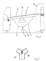
- a suction belt table 1 is shown, between a feeder 2 and a sheet processing machine is arranged. Via the suction belt table 1 an undercurrent arc stream B is guided. This arc current B will generated on the feeder 2 by separation and in the sheet processing Machine further processed.
- a fan 3 is arranged on the suction belt table 1 generates a suction air flow through the box-shaped suction belt table 1.
- two suction air lines 4, 5 are connected to the suction belt table 1, which are connected to a suction air generator 6.
- the suction air lines 4, 5 are connected with additional cavities in the suction belt table 1.
- the suction belt table 1 is shown in more detail in FIG. To the Suction belt table 1, suction belts 7 are guided over guide 8 and Drive rollers 9 and tension rollers 10 are guided.
- the suction belt table 1 itself is formed by a main suction box 11 to which the fan 3 connected.
- a ventilation ring 12 is provided above the fan 3.
- Ventilation ring 12 In the suction air lines 4, 5 between the transverse boxes 13, 14 and the Connector 15 can ventilation elements 17, 18 according to the Ventilation ring 12 may be used, as shown in Figure 2.
- FIG 3 the detail of the connector 15 is shown in more detail.
- the two suction air lines 4, 5 connected to the transverse boxes 13, 14.
- the Connector 15 is in the area between the suction air lines 4, 5 Control valve 19 arranged.
- the control flap 19 is adjustable in three positions. In this case, either one suction air line 4 or the other suction air line 5 closed or both suction air lines 4, 5 are opened. Furthermore the proportion of the suction air on the two transverse boxes 13, 14 can be different are distributed when the arrangement of the control valve 19 in Art a throttle valve is executed.
- a vacuum is applied to the main suction box 11 as a standard via the fan 3.
- a situation can arise, for example, depending on the rigidity of the sheet material at the start of a sheet at the beginning of the suction belt table 1, in which the sheet is not properly sucked in. This is especially the case when the conveying plane of the suction belt table 1 is inclined relatively strongly against the conveying plane on the sheet feeder 2. Since the sheet must then be guided around a kink, it can be very advantageous to set a higher negative pressure in order to be able to suck the sheet in more strongly at the entry point.
- the transverse box 13 is more strongly supplied with suction air or with a higher vacuum at the front end of the suction belt table 1 in the direction of sheet travel.
- This is possible by means of the control flap 19 in the connecting piece 15.
- the control flap 19 is adjusted in the direction of the suction air line 5, which supplies the cross box 14 and thus the suction air line 4 to the cross box 13 is opened more.
- the ventilation element 17 in the suction air line 4 is also possible to adjust the ventilation element 17 in the suction air line 4 to influence the negative pressure in the transverse box 13.
- An adjustable opening for the defined suction of ambient air is created via the ventilation element 17. Since the transverse box 13 is constantly covered by sheets from its top in continuous operation, this represents a good control option.
- an increased pressure may be required in the outlet area of the suction belt table 1 in certain operating states.
- This in turn can also be achieved by switching in the connector 15.
- the transverse box 14 is more strongly supplied with suction air or with a higher vacuum at the rear end of the suction belt table 1 in the direction of sheet travel.
- the control flap 19 is adjusted in the direction of the suction air line 4, which supplies the cross box 13 and thus the suction air line 5 to the cross box 14 is opened more.
- An adjustable opening for the defined suction of ambient air is created via the ventilation element 18. Since the transverse box 14 is constantly covered by arches from its upper side in continuous operation, this also represents a good control option here.
- the negative pressure in the cross box 14 at the outlet of the suction belt table 1 can be switched off when the first sheets are transported to the suction belt table 1, as a result of which the full suction power of the suction air generator 6 is applied to the cross box 13 in the inlet area of the suction belt table 1.
- the suction belt table 1 is still largely empty and the suction air can be used in full on the inlet side, so that the first sheets can also be properly fed to the suction belt table 1.
- no suction air is conducted as the cross box 14 on the outlet side, since it would be ineffective at the open suction belts 7 anyway.
- the negative pressure in the transverse box 14 at the outlet of the suction belt table 1 can also be switched off when the last sheets run over the suction belt table 1. This is important so that they can be properly aligned.
- the next sheet is covered by the next sheet in the shingling from below relative to the suction belts 7 and thus automatically released at the end of the suction belt table 1 for alignment in the contact area of the sheet-processing machine. This is no longer the case when the last sheet is fed into the sheet processing machine. Therefore, the suction air should be turned off at the cross box 14.
- the suction air, which in turn is directed to the first transverse box 13, has no effect on the suction belts 7 which are open at this time and cannot produce a malfunction.
- the elements for air control can be provided to be remotely controllable and with the control of the sheet feeder 2 or Sheet processing machine or to connect both. This allows depict an automated procedure in which everything for the operation of the Operating conditions occurring in the sheet-processing machine can be mapped.
- the facilities for air supply i.e. the fan 3 and the suction air generator 6, as well as to the provided regulating devices i.e. on the ventilation ring 12 before Main suction box 11 and on the ventilation elements 17, 18 in front of the cross boxes 13, 14 a favorable for the continuous operation of the suction belt table 1 Basic settings are made.
- control valve 19 In operation of the suction belt table 1 then in the simplest case solely via the control technology in the Machine operation integrated positioning of the control valve 19 die Influencing the sheet transport properties in those described above Function levels of the suction belt table 1 possible.
- Control valve 19 with properties for regulating the air flow are further simplifications and remotely controllable adjustments to the operating procedure possible.
Landscapes
- Engineering & Computer Science (AREA)
- Mechanical Engineering (AREA)
- Delivering By Means Of Belts And Rollers (AREA)
- Electrical Discharge Machining, Electrochemical Machining, And Combined Machining (AREA)
- Valve Device For Special Equipments (AREA)
Applications Claiming Priority (2)
| Application Number | Priority Date | Filing Date | Title |
|---|---|---|---|
| DE19947554 | 1999-10-02 | ||
| DE19947554A DE19947554C2 (de) | 1999-10-02 | 1999-10-02 | Anlegetisch |
Publications (3)
| Publication Number | Publication Date |
|---|---|
| EP1088778A2 true EP1088778A2 (fr) | 2001-04-04 |
| EP1088778A3 EP1088778A3 (fr) | 2002-12-04 |
| EP1088778B1 EP1088778B1 (fr) | 2004-11-03 |
Family
ID=7924315
Family Applications (1)
| Application Number | Title | Priority Date | Filing Date |
|---|---|---|---|
| EP00118358A Expired - Lifetime EP1088778B1 (fr) | 1999-10-02 | 2000-08-24 | Table de marge |
Country Status (3)
| Country | Link |
|---|---|
| EP (1) | EP1088778B1 (fr) |
| AT (1) | ATE281390T1 (fr) |
| DE (2) | DE19947554C2 (fr) |
Families Citing this family (5)
| Publication number | Priority date | Publication date | Assignee | Title |
|---|---|---|---|---|
| DE10213705C5 (de) * | 2001-04-26 | 2017-01-05 | Heidelberger Druckmaschinen Ag | Vorrichtung zum Fördern eines Bogenstroms von einem Bogenstapel zu einer bogenverarbeitenden Maschine |
| DE102005009223A1 (de) * | 2005-03-01 | 2006-09-07 | Koenig & Bauer Ag | Saugbändertisch |
| DE102005009289A1 (de) * | 2005-03-01 | 2006-09-07 | Koenig & Bauer Ag | Saugbändertisch |
| DE102011116365A1 (de) * | 2011-10-19 | 2013-04-25 | Heidelberger Druckmaschinen Aktiengesellschaft | Bogenbearbeitungsmaschine mit Bogenanleger mit Saugbandmodul |
| CN103693468B (zh) * | 2013-12-31 | 2016-09-14 | 株洲三新包装技术有限公司 | 纸板印刷机风箱组负压抽风装置及瓦楞纸板水性印刷机 |
Family Cites Families (5)
| Publication number | Priority date | Publication date | Assignee | Title |
|---|---|---|---|---|
| DE3838078C3 (de) * | 1988-11-10 | 1998-08-13 | Roland Man Druckmasch | Vorrichtung zum Fördern eines Stroms von Bogen |
| DE4013302A1 (de) * | 1990-04-26 | 1991-10-31 | Koenig & Bauer Ag | Vorrichtung zum foerdern eines insbesondere geschuppten stroms von bogen |
| DE4416289C2 (de) * | 1994-05-07 | 2003-06-05 | Heidelberger Druckmasch Ag | Vorrichtung zum Fördern eines geschuppten Bogenstromes |
| DE4416286C2 (de) * | 1994-05-07 | 1999-10-28 | Heidelberger Druckmasch Ag | Vorrichtung zur Anpassung des Unterdruckes in einem Saugbandzuführtisch eines Bogenanlegers |
| DE4442629C2 (de) * | 1994-12-01 | 1998-05-07 | Heidelberger Druckmasch Ag | Saugbändertisch |
-
1999
- 1999-10-02 DE DE19947554A patent/DE19947554C2/de not_active Expired - Fee Related
-
2000
- 2000-08-24 EP EP00118358A patent/EP1088778B1/fr not_active Expired - Lifetime
- 2000-08-24 DE DE50008490T patent/DE50008490D1/de not_active Expired - Lifetime
- 2000-08-24 AT AT00118358T patent/ATE281390T1/de active
Also Published As
| Publication number | Publication date |
|---|---|
| DE19947554A1 (de) | 2001-04-12 |
| EP1088778A3 (fr) | 2002-12-04 |
| EP1088778B1 (fr) | 2004-11-03 |
| DE50008490D1 (de) | 2004-12-09 |
| DE19947554C2 (de) | 2003-11-27 |
| ATE281390T1 (de) | 2004-11-15 |
Similar Documents
| Publication | Publication Date | Title |
|---|---|---|
| EP0454011B1 (fr) | Dispositif pour convoyer un courant de feuilles, en particulier un courant en écaille | |
| DE69801185T2 (de) | Blattübergabesystem mit Förderband und Sauggebläse | |
| DE202004006615U1 (de) | Fördertisch | |
| DE19817175A1 (de) | Vorrichtung zum Fördern eines insbesondere geschuppten Stroms von Bogen zu einer bogenverarbeitenden Maschine | |
| EP0006522A1 (fr) | Procédé et dispositif d'ouverture de produits d'imprimerie pliés | |
| EP1197450A2 (fr) | Commande d'un couteau à air pulsé pour un mécanisme d'alimentation au moyen d'une bande sous vide | |
| EP1088778B1 (fr) | Table de marge | |
| DE60127431T2 (de) | Vorrichtung zur stapelung von bögen | |
| EP1588967B1 (fr) | Table de transport | |
| EP0088885B1 (fr) | Margeur pour machines de traitement de feuilles | |
| EP1010525B1 (fr) | Dispositif de guidage de feuilles pour une machine d'impression | |
| EP2620400B1 (fr) | Dispositif de tansport de tableaux en tôle dans une machine d'impression de tôle ou une machine de laquage de tôle | |
| EP0798251A2 (fr) | Convoyeur à succion | |
| DE102019133570B4 (de) | Seitliche Bogenausrichtung | |
| DE102019133573B4 (de) | Seitliche Bogenausrichtung mit Saugerreinigung | |
| DE19649824A1 (de) | Saugförderer | |
| EP1090863B1 (fr) | Table de marge | |
| DE102008049809A1 (de) | Bogenfördervorrichtung | |
| DE102017208091B4 (de) | Bogenzuführvorrichtung für eine Druckmaschine | |
| EP0822154A2 (fr) | Dispositif pour alimenter des feuilles vers une machine à imprimer | |
| DE102005009223A1 (de) | Saugbändertisch | |
| EP3068714A1 (fr) | Commande d'air pour tête d'aspiration | |
| DE20310194U1 (de) | Fördertisch | |
| DE102019133574A1 (de) | Saugkammeranordnung für seitliche Bogenausrichtung | |
| DE102005009289A1 (de) | Saugbändertisch |
Legal Events
| Date | Code | Title | Description |
|---|---|---|---|
| PUAI | Public reference made under article 153(3) epc to a published international application that has entered the european phase |
Free format text: ORIGINAL CODE: 0009012 |
|
| AK | Designated contracting states |
Kind code of ref document: A2 Designated state(s): AT BE CH CY DE DK ES FI FR GB GR IE IT LI LU MC NL PT SE |
|
| AX | Request for extension of the european patent |
Free format text: AL;LT;LV;MK;RO;SI |
|
| PUAL | Search report despatched |
Free format text: ORIGINAL CODE: 0009013 |
|
| AK | Designated contracting states |
Kind code of ref document: A3 Designated state(s): AT BE CH CY DE DK ES FI FR GB GR IE IT LI LU MC NL PT SE |
|
| AX | Request for extension of the european patent |
Free format text: AL;LT;LV;MK;RO;SI |
|
| 17P | Request for examination filed |
Effective date: 20021022 |
|
| AKX | Designation fees paid |
Designated state(s): AT BE CH CY DE DK ES FI FR GB GR IE IT LI LU MC NL PT SE |
|
| 17Q | First examination report despatched |
Effective date: 20030904 |
|
| GRAP | Despatch of communication of intention to grant a patent |
Free format text: ORIGINAL CODE: EPIDOSNIGR1 |
|
| GRAS | Grant fee paid |
Free format text: ORIGINAL CODE: EPIDOSNIGR3 |
|
| GRAA | (expected) grant |
Free format text: ORIGINAL CODE: 0009210 |
|
| AK | Designated contracting states |
Kind code of ref document: B1 Designated state(s): AT BE CH CY DE DK ES FI FR GB GR IE IT LI LU MC NL PT SE |
|
| PG25 | Lapsed in a contracting state [announced via postgrant information from national office to epo] |
Ref country code: FI Free format text: LAPSE BECAUSE OF FAILURE TO SUBMIT A TRANSLATION OF THE DESCRIPTION OR TO PAY THE FEE WITHIN THE PRESCRIBED TIME-LIMIT Effective date: 20041103 Ref country code: IT Free format text: LAPSE BECAUSE OF FAILURE TO SUBMIT A TRANSLATION OF THE DESCRIPTION OR TO PAY THE FEE WITHIN THE PRESCRIBED TIME-LIMIT;WARNING: LAPSES OF ITALIAN PATENTS WITH EFFECTIVE DATE BEFORE 2007 MAY HAVE OCCURRED AT ANY TIME BEFORE 2007. THE CORRECT EFFECTIVE DATE MAY BE DIFFERENT FROM THE ONE RECORDED. Effective date: 20041103 Ref country code: NL Free format text: LAPSE BECAUSE OF FAILURE TO SUBMIT A TRANSLATION OF THE DESCRIPTION OR TO PAY THE FEE WITHIN THE PRESCRIBED TIME-LIMIT Effective date: 20041103 Ref country code: IE Free format text: LAPSE BECAUSE OF FAILURE TO SUBMIT A TRANSLATION OF THE DESCRIPTION OR TO PAY THE FEE WITHIN THE PRESCRIBED TIME-LIMIT Effective date: 20041103 Ref country code: FR Free format text: LAPSE BECAUSE OF FAILURE TO SUBMIT A TRANSLATION OF THE DESCRIPTION OR TO PAY THE FEE WITHIN THE PRESCRIBED TIME-LIMIT Effective date: 20041103 Ref country code: GB Free format text: LAPSE BECAUSE OF FAILURE TO SUBMIT A TRANSLATION OF THE DESCRIPTION OR TO PAY THE FEE WITHIN THE PRESCRIBED TIME-LIMIT Effective date: 20041103 |
|
| REG | Reference to a national code |
Ref country code: GB Ref legal event code: FG4D Free format text: NOT ENGLISH |
|
| REG | Reference to a national code |
Ref country code: CH Ref legal event code: EP |
|
| REF | Corresponds to: |
Ref document number: 50008490 Country of ref document: DE Date of ref document: 20041209 Kind code of ref document: P |
|
| REG | Reference to a national code |
Ref country code: IE Ref legal event code: FG4D Free format text: GERMAN |
|
| PG25 | Lapsed in a contracting state [announced via postgrant information from national office to epo] |
Ref country code: SE Free format text: LAPSE BECAUSE OF FAILURE TO SUBMIT A TRANSLATION OF THE DESCRIPTION OR TO PAY THE FEE WITHIN THE PRESCRIBED TIME-LIMIT Effective date: 20050203 Ref country code: GR Free format text: LAPSE BECAUSE OF FAILURE TO SUBMIT A TRANSLATION OF THE DESCRIPTION OR TO PAY THE FEE WITHIN THE PRESCRIBED TIME-LIMIT Effective date: 20050203 Ref country code: DK Free format text: LAPSE BECAUSE OF FAILURE TO SUBMIT A TRANSLATION OF THE DESCRIPTION OR TO PAY THE FEE WITHIN THE PRESCRIBED TIME-LIMIT Effective date: 20050203 |
|
| PG25 | Lapsed in a contracting state [announced via postgrant information from national office to epo] |
Ref country code: ES Free format text: LAPSE BECAUSE OF FAILURE TO SUBMIT A TRANSLATION OF THE DESCRIPTION OR TO PAY THE FEE WITHIN THE PRESCRIBED TIME-LIMIT Effective date: 20050214 |
|
| NLV1 | Nl: lapsed or annulled due to failure to fulfill the requirements of art. 29p and 29m of the patents act | ||
| GBV | Gb: ep patent (uk) treated as always having been void in accordance with gb section 77(7)/1977 [no translation filed] |
Effective date: 20041103 |
|
| REG | Reference to a national code |
Ref country code: IE Ref legal event code: FD4D |
|
| PG25 | Lapsed in a contracting state [announced via postgrant information from national office to epo] |
Ref country code: LU Free format text: LAPSE BECAUSE OF NON-PAYMENT OF DUE FEES Effective date: 20050824 Ref country code: CY Free format text: LAPSE BECAUSE OF FAILURE TO SUBMIT A TRANSLATION OF THE DESCRIPTION OR TO PAY THE FEE WITHIN THE PRESCRIBED TIME-LIMIT Effective date: 20050824 |
|
| PG25 | Lapsed in a contracting state [announced via postgrant information from national office to epo] |
Ref country code: LI Free format text: LAPSE BECAUSE OF NON-PAYMENT OF DUE FEES Effective date: 20050831 Ref country code: BE Free format text: LAPSE BECAUSE OF NON-PAYMENT OF DUE FEES Effective date: 20050831 Ref country code: MC Free format text: LAPSE BECAUSE OF NON-PAYMENT OF DUE FEES Effective date: 20050831 Ref country code: CH Free format text: LAPSE BECAUSE OF NON-PAYMENT OF DUE FEES Effective date: 20050831 |
|
| PLBE | No opposition filed within time limit |
Free format text: ORIGINAL CODE: 0009261 |
|
| STAA | Information on the status of an ep patent application or granted ep patent |
Free format text: STATUS: NO OPPOSITION FILED WITHIN TIME LIMIT |
|
| 26N | No opposition filed |
Effective date: 20050804 |
|
| EN | Fr: translation not filed | ||
| REG | Reference to a national code |
Ref country code: CH Ref legal event code: PL |
|
| BERE | Be: lapsed |
Owner name: *MAN ROLAND DRUCKMASCHINEN A.G. Effective date: 20050831 |
|
| PG25 | Lapsed in a contracting state [announced via postgrant information from national office to epo] |
Ref country code: PT Free format text: LAPSE BECAUSE OF NON-PAYMENT OF DUE FEES Effective date: 20050403 |
|
| PGFP | Annual fee paid to national office [announced via postgrant information from national office to epo] |
Ref country code: AT Payment date: 20110812 Year of fee payment: 12 |
|
| REG | Reference to a national code |
Ref country code: DE Ref legal event code: R081 Ref document number: 50008490 Country of ref document: DE Owner name: MANROLAND SHEETFED GMBH, DE Free format text: FORMER OWNER: MANROLAND AG, 63075 OFFENBACH, DE Effective date: 20120509 |
|
| REG | Reference to a national code |
Ref country code: AT Ref legal event code: MM01 Ref document number: 281390 Country of ref document: AT Kind code of ref document: T Effective date: 20120824 |
|
| PG25 | Lapsed in a contracting state [announced via postgrant information from national office to epo] |
Ref country code: AT Free format text: LAPSE BECAUSE OF NON-PAYMENT OF DUE FEES Effective date: 20120824 |
|
| PGFP | Annual fee paid to national office [announced via postgrant information from national office to epo] |
Ref country code: DE Payment date: 20130821 Year of fee payment: 14 |
|
| REG | Reference to a national code |
Ref country code: DE Ref legal event code: R119 Ref document number: 50008490 Country of ref document: DE |
|
| REG | Reference to a national code |
Ref country code: DE Ref legal event code: R119 Ref document number: 50008490 Country of ref document: DE Effective date: 20150303 |
|
| PG25 | Lapsed in a contracting state [announced via postgrant information from national office to epo] |
Ref country code: DE Free format text: LAPSE BECAUSE OF NON-PAYMENT OF DUE FEES Effective date: 20150303 |