EP1089006A2 - Servo-embrayage hydropneumatique et système comprenant le dite aussi que méthode utilisée - Google Patents
Servo-embrayage hydropneumatique et système comprenant le dite aussi que méthode utilisée Download PDFInfo
- Publication number
- EP1089006A2 EP1089006A2 EP00120281A EP00120281A EP1089006A2 EP 1089006 A2 EP1089006 A2 EP 1089006A2 EP 00120281 A EP00120281 A EP 00120281A EP 00120281 A EP00120281 A EP 00120281A EP 1089006 A2 EP1089006 A2 EP 1089006A2
- Authority
- EP
- European Patent Office
- Prior art keywords
- piston
- clutch
- hydropneumatic
- housing
- pneumatic
- Prior art date
- Legal status (The legal status is an assumption and is not a legal conclusion. Google has not performed a legal analysis and makes no representation as to the accuracy of the status listed.)
- Granted
Links
Images


Classifications
-
- F—MECHANICAL ENGINEERING; LIGHTING; HEATING; WEAPONS; BLASTING
- F16—ENGINEERING ELEMENTS AND UNITS; GENERAL MEASURES FOR PRODUCING AND MAINTAINING EFFECTIVE FUNCTIONING OF MACHINES OR INSTALLATIONS; THERMAL INSULATION IN GENERAL
- F16D—COUPLINGS FOR TRANSMITTING ROTATION; CLUTCHES; BRAKES
- F16D25/00—Fluid-actuated clutches
- F16D25/12—Details not specific to one of the before-mentioned types
- F16D25/14—Fluid pressure control
-
- F—MECHANICAL ENGINEERING; LIGHTING; HEATING; WEAPONS; BLASTING
- F16—ENGINEERING ELEMENTS AND UNITS; GENERAL MEASURES FOR PRODUCING AND MAINTAINING EFFECTIVE FUNCTIONING OF MACHINES OR INSTALLATIONS; THERMAL INSULATION IN GENERAL
- F16D—COUPLINGS FOR TRANSMITTING ROTATION; CLUTCHES; BRAKES
- F16D25/00—Fluid-actuated clutches
- F16D25/12—Details not specific to one of the before-mentioned types
-
- F—MECHANICAL ENGINEERING; LIGHTING; HEATING; WEAPONS; BLASTING
- F16—ENGINEERING ELEMENTS AND UNITS; GENERAL MEASURES FOR PRODUCING AND MAINTAINING EFFECTIVE FUNCTIONING OF MACHINES OR INSTALLATIONS; THERMAL INSULATION IN GENERAL
- F16D—COUPLINGS FOR TRANSMITTING ROTATION; CLUTCHES; BRAKES
- F16D48/00—External control of clutches
- F16D48/02—Control by fluid pressure
- F16D48/04—Control by fluid pressure providing power assistance
-
- F—MECHANICAL ENGINEERING; LIGHTING; HEATING; WEAPONS; BLASTING
- F16—ENGINEERING ELEMENTS AND UNITS; GENERAL MEASURES FOR PRODUCING AND MAINTAINING EFFECTIVE FUNCTIONING OF MACHINES OR INSTALLATIONS; THERMAL INSULATION IN GENERAL
- F16D—COUPLINGS FOR TRANSMITTING ROTATION; CLUTCHES; BRAKES
- F16D48/00—External control of clutches
- F16D48/02—Control by fluid pressure
- F16D2048/0215—Control by fluid pressure for damping of pulsations within the fluid system
-
- F—MECHANICAL ENGINEERING; LIGHTING; HEATING; WEAPONS; BLASTING
- F16—ENGINEERING ELEMENTS AND UNITS; GENERAL MEASURES FOR PRODUCING AND MAINTAINING EFFECTIVE FUNCTIONING OF MACHINES OR INSTALLATIONS; THERMAL INSULATION IN GENERAL
- F16D—COUPLINGS FOR TRANSMITTING ROTATION; CLUTCHES; BRAKES
- F16D48/00—External control of clutches
- F16D48/02—Control by fluid pressure
- F16D2048/0227—Source of pressure producing the clutch engagement or disengagement action within a circuit; Means for initiating command action in power assisted devices
- F16D2048/0254—Double actuation, i.e. two actuation means can produce independently an engagement or disengagement of the clutch
-
- F—MECHANICAL ENGINEERING; LIGHTING; HEATING; WEAPONS; BLASTING
- F16—ENGINEERING ELEMENTS AND UNITS; GENERAL MEASURES FOR PRODUCING AND MAINTAINING EFFECTIVE FUNCTIONING OF MACHINES OR INSTALLATIONS; THERMAL INSULATION IN GENERAL
- F16D—COUPLINGS FOR TRANSMITTING ROTATION; CLUTCHES; BRAKES
- F16D2300/00—Special features for couplings or clutches
- F16D2300/22—Vibration damping
Definitions
- the present invention relates to a hydropneumatic clutch booster according to the preamble of claim 1, provided with such a clutch booster Coupling system according to the preamble of claim 16 and a suitable for this Method according to the preamble of claim 19.
- Known clutch systems consist of a hydraulic master cylinder, which on the The vehicle's pedals are assembled and consist of a clutch booster attached to the transmission is appropriate.
- Such known coupling systems require due to the distributed arrangement of the individual components in total too much installation space. Their manufacture is also due to the large number of self-contained subsystems and the associated ones Variety of parts complex and therefore expensive.
- An exemplary embodiment of a clutch booster mentioned above or an actuating device for the pneumatic actuation of a friction clutch is known from DE 197 16 600 A1.
- An actuator discloses, for in the drive train of a commercial vehicle, between an internal combustion engine and a gearbox arranged in a bell housing friction clutch.
- These Actuating device described comprises a substantially coaxial with the friction clutch movable release bearing arrangement for actuating the friction clutch, a positioning servo arrangement with a pneumatic power cylinder arrangement acting on the release bearing arrangement, which in turn is connected to a pneumatic source Control valve dependent on a command variable representing a soliposition and one the actual position representing the axial position of the release bearing arrangement can be actuated.
- This known actuator or this clutch booster is due its very complex structure is also complex to manufacture.
- EP 0 751 315 B1 by the same applicant describes a hydropneumatic for the first time Clutch booster that has proven itself in everyday life.
- This hydropneumatic Coupling booster has a preferably structural on its housing Integrated control part in the form of a control valve which, when subjected to hydraulic pressure by a foot pedal force on a control piston on a pneumatic inlet and Exhaust valve for the compressed air supply to the pneumatic servo piston acts.
- Coupling boosters of this type are intended to force the foot pedal by means of compressed air Reinforce servo pistons proportionally.
- a non-generic compressed air working cylinder for a brake booster known that a hydraulic master cylinder and a pneumatic Compressed air working cylinder, each with pistons arranged therein, in which Compressed air working cylinder at least one control or actuating piston and one servo piston are included.
- the actuating piston of the pneumatic working cylinder in turn contains an inlet and outlet valve for compressed air, which is intended to serve as brake booster.
- the Control piston actuated by the brake pedal controls via the integrated intake / exhaust valve the pressure acting on the servo or working piston, whereby the working piston in turn, the braking force increased by the compressed air by means of a plunger on the Hydraulic piston transmits. The latter then acts hydraulically on the brakes.
- hydropneumatic clutch booster known from EP 0 751 315 B1 it is therefore an object of the present invention to provide a hydropneumatic To propose a clutch booster and a clutch system based thereon, its design is as compact as possible, for example for installation in the pedals.
- Another object of the present invention is to provide a hydropneumatic clutch booster propose, which is characterized by a small number of components and characterized by a simple structure or a low tendency to wear.
- the object of the invention is a suitable one Specify procedure.
- hydropneumatic clutch boosters Due to the first reversal in hydropneumatic clutch boosters the arrangement of pneumatic and hydraulic pistons in such a way that the pneumatic Piston first with the clutch signal initiated by a stamp or the Pedal force is applied, and this in turn arranged in the same compact housing controlled hydraulic pistons, the number has been successfully managed for the first time of the individual components of such a hydropneumatic clutch booster as to decisively reduce also a coupling system based thereon according to claim 16, the individual parts or components which build up the power amplifier as such can be kept structurally simpler in an advantageous manner. Consequently could simplify the assembly of this hydropneumatic clutch booster can be achieved, the reduced tendency to wear to a noticeable Increasing the service life and thus improving the ease of maintenance, which in turn is reflected in a reduction in costs.
- DE-AS 1 576 178 Such a reversal of the arrangement is indeed from the non-generic DE-AS 1 576 178 of pneumatic and hydraulic pistons in a hydropneumatic brake booster known.
- the hydropneumatic brake booster disclosed in DE-AS 1 576 178 is the different braking force requirements for a solo driver Tractor, which is often used as a light truck, and a tractor cover with a trailer with only one brake booster, which is then two different Brake boosters should provide.
- the pneumatic includes Cylinder a control piston with an integrated inlet / outlet valve and a servo or working piston with a first surface F and a second, annular arranged around it a second servo or working piston with an additional one Area f, so that an increase in the brake force boost by its connection the enlargement of the servo area from F to F + f can be achieved. Also exist at this brake booster has no special requirements on its hysteresis, what by the sealing of the control piston becomes clear by means of two sealing rings.
- control piston of the hydropneumatic brake booster is after the DE-AS 1 576 178 unstable due to the integrated inlet / outlet valve.
- the transfer the working principle of such a brake booster on a clutch booster for clutch actuation is therefore excluded.
- the controlled Pneumatic pressure acts directly on the brake booster according to DE-AS 1 576 178 on the actuating or control piston.
- the forces in the control piston therefore vary according to the set pressure.
- the control piston becomes unstable Condition caused by a maneuvering of a vehicle with such a booster would make it much more difficult. This would not be a sensitive gradation or control realizable.
- the hydropneumatic clutch booster in contrast, the hydropneumatic clutch booster according to the invention the inlet / outlet valve integrated in the pneumatic piston or in the servo piston.
- This inlet / outlet valve is used to control those to be controlled for power amplification Compressed air, its opening or closing in turn in the front as an actuating piston trained stamp is controlled.
- This means that the pressure entered does not have an effect Stamp itself out, which ensures a constant actuation force regardless of the pressure entered can apply, which thus enables a particularly sensitive control of the clutch.
- the hydraulic piston which in turn has suitable means, such as a Hydraulic line, a clutch actuator, such as one on the transmission arranged master cylinder or a central release integrated in the transmission or the like can apply the required coupling force, advantageously follows for the first time the movement of the pneumatic piston, which in turn is carried out by a pressure sensor spring specifically controlled or regulated to the clutch signals impressed via a stamp or pedal forces from the clutch pedal responds.
- suitable means such as a Hydraulic line
- a clutch actuator such as one on the transmission arranged master cylinder or a central release integrated in the transmission or the like
- a limit or threshold value is impressed on the pressure sensor spring. Below this threshold value keeps a pressure away from the pneumatic piston. Above this Threshold value, the pneumatic piston is pressurized and close to the Threshold, the pressure on the pneumatic piston is kept constant.
- the rod is used advantageously a direct contact from the piston designed as an actuating piston to the hydraulic one Piston ensured so that even in such an emergency a safe operation of the Coupling is guaranteed.
- a hydraulic reservoir for the hydraulic oil of the hydraulic piston can be used directly be integrated on or in the hydropneumatic clutch booster, what further helps to keep the entire assembly as compact as possible.
- This power amplifier according to the invention as well as an inventive one constructed with it Power amplification system can of course also be used for other tasks such as used for strengthening when using other devices become.
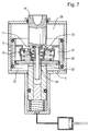
- FIG. 1 is a schematic representation of an exemplary embodiment of the invention Hydropneumatic clutch booster shown.
- a cylindrical one Housing 1 of a pneumatic piston has an air inlet 2 for controlling Compressed air and an exhaust air outlet 3 for controlling compressed air and one, the housing against a stamp 10 sealing ring 4, preferably as an O-ring seal can be trained.
- a sliding therein Sealed piston 5 is provided, which in turn has a seat 6.
- the seat 6 is preferably designed as a sealing seat 6 and is disc-shaped Shoulder spaced radially inward from the piston wall.
- the piston also has 5 via an air duct 7 arranged in the piston wall, one preferably as Clamping ring 8 trained stop and two outer seals 9a, 9b and an inner one Seal 9c. These seals are preferably designed as an O-ring seal.
- a stamp 10 projects into the housing 1 and is displaceable in the direction of its longitudinal axis is stored.
- This stamp 10 has on its inside facing the housing 1 End via a seat 11, which is preferably designed as an annular sealing seat is.
- a rod 13 extends further into the housing 1 starting from the stamp 10 Rod 13 is preferably arranged coaxially or coaxially with the stamp 10.
- Staff 13 and Stamps 10 are connected in a suitable manner, but they can also be used as one be made in one piece stamp-rod element.
- One extends around the rod 13 preferably designed as a pressure sensor spring 12 coil spring.
- An essentially disc-shaped Valve carrier 14 is connected to the piston 5 via the clamping ring 8 Stop connected. The connection point between valve carrier 14 and piston 5 is through the seal 9c sealed.
- the valve carrier has two adjacent ring-shaped ones Walls whose direction of extension parallel to the longitudinal axis of the housing 1 or the stamp 10 runs that as a stop or to support corresponding inner and outer Lips or flanks of an inlet /
- the annular inlet / outlet valve 15 is preferably made of rubber and has an essentially U-shaped cross section.
- the stamp-side end of the housing 1 facing the top an annular flat Seat, in particular a sealing seat, both with the sealing seat 6 of the piston 5 and can seal with the sealing seat 11 of the stamp 10 when lying one on top of the other.
- a pressure equalization bore 16 formed passage is provided between the diameters of these two annular sealing seats in the valve 15 .
- a retaining spring 17 is fitted between the valve support 14 and the valve 15.
- a cylindrical housing is connected to the housing 1 of the pneumatic piston 5 18 of a hydraulic piston 21 which, for this purpose, is flange-mounted or on a other suitable way can be attached.
- the housing 18 of the hydraulic piston can but also be part of the cylindrical housing 1 of the pneumatic piston 5.
- the housing 1 and the housing 18 together form a very compact, space-saving common Housing of the hydropneumatic clutch booster.
- the housing 18 of the hydraulic Piston 18 has an outlet 19 for controlling hydraulic oil.
- a hydraulic piston 20 is slidably supported by a retaining spring 21 is biased against the valve support 14 in the direction of the punch 10.
- the longitudinal axis of the hydraulic piston 20 extends parallel or coaxial to the axis of the plunger 10 or of the pneumatic piston 5, the hydraulic piston 20 at least over one section is hollow or has a central bore or blind hole-like recess starting from its end facing the stamp 10 extends inside. This recess or bore is dimensioned so that it includes the rod 13 of the stamp 10 therein can absorb sufficient play smoothly.
- the piston 20 also has a radial arranged groove 22, which allows the compressed air, from the inside of the piston 20 to the outside or flow in the opposite direction if necessary. With a suitable sealing ring 23 or the hydraulic section or the hydraulic piston 20 against the Housing 18 sealed reliably.
- a clutch actuation device 25 which is arranged, for example, on the transmission Master cylinder or be configured as a central release integrated in the transmission can, imprinted.
- a pressure-thrust chamber 25 is through the inner circumference of the pneumatic cylinder 1, the seat 11 of the stamp 10 and by the same, the seat 6 and the sealing ring 9a of the piston 5 delimited or defined.
- An air supply chamber 29 connected to the inlet 2 is through the inner Circumference of the cylinder 1 and through the two O-rings 9a and 9b as well as through the piston 5 limited or defined.
- Another air supply chamber 27, for example the compressed air through the hole 7 in Piston 5 is fed is through the inner circumference of the piston 5, the seat 6, the inner O-ring 9c and the outer lip or flank of the valve 15 limited.
- a compensation chamber 28 which is the pressure above and within the rubber manufactured valve 15 balances, is through the inner and outer lips or flanks of the valve 15 and by the valve 15 itself and the two held by the valve support 14 Walls limited.
- An exhaust chamber 30 is through the inner circumference and the lower cover of the Pneumatic cylinder 1, the O-rings 9b and 9c of the piston 5, the hydraulic piston 20 and the O-ring 23 limited or defined.
- a hydraulic chamber 31 is through the inner periphery and bottom of the cylinder 18 enclosed and limited by the hydraulic piston 20 and its O-ring 23rd
- a variable exhaust passage 23 lies between the sealing seat 11 of the stamp 10 and the opposite surface of the valve 15.
- a variable air intake passage 33 lies between the sealing seat of the pneumatic piston 5 and the opposite Surface of the valve 15.
- a fixed or unchangeable exhaust air passage is limited through the seal seat 11 of the stamp 10, the rod 13, the inner annular wall of the Valve carrier 14 and the inner circumference of the hydraulic piston 20th
- Fig. 2 is the rest position of the embodiment of the invention shown in Fig. 1 Hydropneumatic clutch booster shown.
- This clutch booster is fed by an air supply reservoir, not shown.
- the Compressed air supplied from outside is held in the chambers 29 and 27.
- a withdrawn or largely withdrawn position of the stamp 10 is the passage 32nd open and thus the thrust chamber 26 is ventilated from the atmosphere by the open passage 32, the gap 34, the passage 22, the exhaust air chamber 30 and the exhaust air outlet 3.
- the hydraulic section is therefore not under pressure in this constellation.
- Fig. 3 shows the hydropneumatic clutch booster with a small initial stroke of the stamp 14.
- the stamp 10 is pushed against the pressure sensor spring 12, with a load equal to the threshold.
- the spring pushes 12 the valve carrier 14, the pneumatic piston 5 and the hydraulic piston 20 against the spring 21 and thus works against the hydraulic pressure, which is now due to the Movement of the piston 20 is built up within the hydraulic cylinder 18.
- the sensor spring 12 is shortened due to the load impressed by the stamp 10, so that the seat 11 of the stamp 10 the surface of the valve 14 made of rubber touches, and thus closes the exhaust air passage 32.
- the chamber is in this configuration 26 no longer vented to the atmosphere.
- the activation is the clutch actuation device 25 is nevertheless secured by mechanical means, as shown in more detail in Fig. 8. Due to the lack of support from the Compressed air assumed in this example due to a defect in the pneumatic Circulation is not present, the plunger 10 pushes the hydraulic piston 20 over the rod 13 ahead after fully opening valve 15.
- the power amplifier according to the invention can be adapted for a variety of uses become and is particularly suitable for the amplification of pedal forces for actuation a clutch of a vehicle, e.g. of a commercial vehicle.
- the present invention thus provides a hydropneumatic booster, in particular a clutch booster for motor vehicles, with one in a cylindrical Housing arranged pneumatic piston and one in another cylindrical Housing arranged hydraulic pistons.
- the hydraulic housing is for example flanged to the pneumatic housing or by other suitable means connected, or part of the same, so that a common, space-saving compact Housing of the hydropneumatic clutch booster is formed.
- a stamp is slidably arranged in the pneumatic housing so that it is by means of a pressure sensor spring and in cooperation with an inlet / outlet valve integrated in the pneumatic piston for a compressed air to be controlled for power amplification, its opening or closing is controlled by the actuating piston, via the pneumatic piston on the hydraulic Piston acts to control a clutch signal impressed on it or by to specifically boost a clutch pedal applied pedal force from a threshold value, so that a clutch can be actuated.
Landscapes
- Engineering & Computer Science (AREA)
- General Engineering & Computer Science (AREA)
- Mechanical Engineering (AREA)
- Physics & Mathematics (AREA)
- Fluid Mechanics (AREA)
- Hydraulic Clutches, Magnetic Clutches, Fluid Clutches, And Fluid Joints (AREA)
- Amplifiers (AREA)
Applications Claiming Priority (2)
| Application Number | Priority Date | Filing Date | Title |
|---|---|---|---|
| DE19946678 | 1999-09-29 | ||
| DE19946678A DE19946678A1 (de) | 1999-09-29 | 1999-09-29 | Hydropneumatischer Kraftverstärker, insbesondere Kupplungskraftverstärker und darauf aufgebautes Kupplungssystem sowie hierfür geeignetes Verfahren |
Publications (3)
| Publication Number | Publication Date |
|---|---|
| EP1089006A2 true EP1089006A2 (fr) | 2001-04-04 |
| EP1089006A3 EP1089006A3 (fr) | 2003-05-14 |
| EP1089006B1 EP1089006B1 (fr) | 2006-11-29 |
Family
ID=7923730
Family Applications (1)
| Application Number | Title | Priority Date | Filing Date |
|---|---|---|---|
| EP00120281A Expired - Lifetime EP1089006B1 (fr) | 1999-09-29 | 2000-09-28 | Servo-embrayage hydropneumatique et système comprenant le dite aussi que méthode utilisée |
Country Status (3)
| Country | Link |
|---|---|
| EP (1) | EP1089006B1 (fr) |
| AT (1) | ATE347053T1 (fr) |
| DE (2) | DE19946678A1 (fr) |
Cited By (8)
| Publication number | Priority date | Publication date | Assignee | Title |
|---|---|---|---|---|
| CN100594310C (zh) * | 2007-12-27 | 2010-03-17 | 瑞立集团瑞安汽车零部件有限公司 | 离合器分离指示与磨损报警系统 |
| CN104074889A (zh) * | 2014-07-08 | 2014-10-01 | 徐月苗 | 离合器助力器上的气缸 |
| CN110185721A (zh) * | 2019-05-16 | 2019-08-30 | 浙江科力车辆控制系统有限公司 | 电控离合器助力器 |
| CN110207793A (zh) * | 2019-06-14 | 2019-09-06 | 梁泉贤 | 一种液压式称重传感器 |
| EP3463962A4 (fr) * | 2016-05-31 | 2020-03-04 | Pyong Hwa Valeo Co., Ltd. | Appareil de prévention de vibration de pédale d'embrayage pour véhicule |
| WO2020048697A1 (fr) * | 2018-09-06 | 2020-03-12 | Knorr-Bremse Systeme für Nutzfahrzeuge GmbH | Dispositif à piston pour un modulateur électropneumatique pour un véhicule, système de piston, modulateur et procédé de fabrication d'un dispositif à piston |
| CN113932008A (zh) * | 2021-10-21 | 2022-01-14 | 贺尔碧格传动技术(常州)有限公司 | 气动换挡助力器的稳压装置 |
| WO2024230879A1 (fr) * | 2023-05-10 | 2024-11-14 | Schaeffler Technologies AG & Co. KG | Système de libération pour actionner un dispositif d'embrayage, et dispositif d'embrayage |
Families Citing this family (8)
| Publication number | Priority date | Publication date | Assignee | Title |
|---|---|---|---|---|
| DE10117624C1 (de) * | 2001-04-07 | 2002-07-11 | Festo Ag & Co | Vorrichtung zur Druckmessung und damit ausgestatteter fluidbetätigter Antrieb |
| DE10162045B4 (de) * | 2001-12-17 | 2005-06-23 | Siemens Ag | Vorrichtung zum Übersetzen einer Auslenkung eines Aktors, insbesondere für ein Einspritzventil |
| DE10255230A1 (de) | 2002-11-26 | 2004-06-09 | Uhde High Pressure Technologies Gmbh | Hochdruckvorrichtung und -verfahren zum hydraulisch-pneumatischen Krafthub für Reinraumanwendungen |
| DE10311481B4 (de) * | 2003-03-15 | 2006-06-14 | Dr.Ing.H.C. F. Porsche Ag | Hydraulische Kupplungsbetätigung für ein Kraftfahrzeug |
| DE102017214547A1 (de) * | 2017-08-21 | 2019-02-21 | Zf Friedrichshafen Ag | Pneumatische Betätigungseinrichtung für ein Kraftfahrzeug |
| CN110410429B (zh) * | 2018-04-27 | 2021-08-13 | 威伯科欧洲有限责任公司 | 用于商用车辆的离合器伺服器组件 |
| EP3620671B1 (fr) * | 2018-09-06 | 2023-04-19 | KNORR-BREMSE Systeme für Nutzfahrzeuge GmbH | Ensemble de piston |
| CN111306219B (zh) * | 2020-02-21 | 2021-08-06 | 东风商用车有限公司 | 一种直推同轴式离合器分离单元 |
Family Cites Families (7)
| Publication number | Priority date | Publication date | Assignee | Title |
|---|---|---|---|---|
| FR1039278A (fr) * | 1950-07-21 | 1953-10-06 | Teves Kg Alfred | Frein à commande hydraulique et à air sous pression, notamment pour les véhiculesautomobiles |
| US3023053A (en) * | 1960-06-30 | 1962-02-27 | Bendix Corp | Pneumatic servomotor unit |
| DE1576178B2 (de) * | 1965-02-15 | 1971-08-05 | Westinghouse Bremsen u Apparate bau GmbH, 3000 Hannover | Druckluftarbeitszylinder |
| DE3321578A1 (de) * | 1983-06-15 | 1984-12-20 | Sachs Systemtechnik Gmbh, 8720 Schweinfurt | Steuerbarer antrieb fuer eine kraftfahrzeug-reibungskupplung |
| DE4405914B4 (de) * | 1994-02-24 | 2012-03-22 | Knorr-Bremse Systeme für Nutzfahrzeuge GmbH | Pneumatischer Arbeitszylinder zum Betätigen einer Kupplung |
| DE19522966A1 (de) * | 1995-06-27 | 1997-01-02 | Knorr Bremse Systeme | Hydropneumatischer Kupplungskraftverstärker, insbesondere für Kraftfahrzeuge |
| ES2150832B1 (es) * | 1996-06-12 | 2001-06-16 | Fichtel & Sachs Ag | Dispositivo de maniobra para la maniobra, en particular maniobra neumatica, de un embrague de friccion. |
-
1999
- 1999-09-29 DE DE19946678A patent/DE19946678A1/de not_active Withdrawn
-
2000
- 2000-09-28 EP EP00120281A patent/EP1089006B1/fr not_active Expired - Lifetime
- 2000-09-28 DE DE50013805T patent/DE50013805D1/de not_active Expired - Lifetime
- 2000-09-28 AT AT00120281T patent/ATE347053T1/de not_active IP Right Cessation
Cited By (9)
| Publication number | Priority date | Publication date | Assignee | Title |
|---|---|---|---|---|
| CN100594310C (zh) * | 2007-12-27 | 2010-03-17 | 瑞立集团瑞安汽车零部件有限公司 | 离合器分离指示与磨损报警系统 |
| CN104074889A (zh) * | 2014-07-08 | 2014-10-01 | 徐月苗 | 离合器助力器上的气缸 |
| EP3463962A4 (fr) * | 2016-05-31 | 2020-03-04 | Pyong Hwa Valeo Co., Ltd. | Appareil de prévention de vibration de pédale d'embrayage pour véhicule |
| WO2020048697A1 (fr) * | 2018-09-06 | 2020-03-12 | Knorr-Bremse Systeme für Nutzfahrzeuge GmbH | Dispositif à piston pour un modulateur électropneumatique pour un véhicule, système de piston, modulateur et procédé de fabrication d'un dispositif à piston |
| CN110185721A (zh) * | 2019-05-16 | 2019-08-30 | 浙江科力车辆控制系统有限公司 | 电控离合器助力器 |
| CN110207793A (zh) * | 2019-06-14 | 2019-09-06 | 梁泉贤 | 一种液压式称重传感器 |
| CN113932008A (zh) * | 2021-10-21 | 2022-01-14 | 贺尔碧格传动技术(常州)有限公司 | 气动换挡助力器的稳压装置 |
| CN113932008B (zh) * | 2021-10-21 | 2022-11-11 | 贺尔碧格传动技术(常州)有限公司 | 气动换挡助力器的稳压装置 |
| WO2024230879A1 (fr) * | 2023-05-10 | 2024-11-14 | Schaeffler Technologies AG & Co. KG | Système de libération pour actionner un dispositif d'embrayage, et dispositif d'embrayage |
Also Published As
| Publication number | Publication date |
|---|---|
| ATE347053T1 (de) | 2006-12-15 |
| DE50013805D1 (de) | 2007-01-11 |
| EP1089006A3 (fr) | 2003-05-14 |
| EP1089006B1 (fr) | 2006-11-29 |
| DE19946678A1 (de) | 2001-04-19 |
Similar Documents
| Publication | Publication Date | Title |
|---|---|---|
| DE19511811B4 (de) | Elektronisch steuerbare Bremsanlage für Landfahrzeuge und Verfahren zu deren Betrieb | |
| EP1089006B1 (fr) | Servo-embrayage hydropneumatique et système comprenant le dite aussi que méthode utilisée | |
| DE19716600A1 (de) | Betätigungseinrichtung für die Betätigung, insbesondere pneumatische Betätigung einer Reibungskupplung | |
| DE3920766A1 (de) | Unterdruckbremskraftverstaerker fuer eine schlupfgeregelte bremsanlage | |
| DE3315730C2 (de) | Hydraulischer Kraftverstärker | |
| DE4446525A1 (de) | Hydraulische Kraftfahrzeugbremsanlage | |
| EP3408551B1 (fr) | Actionneur, en particulier cylindre récepteur, pour un dispositif permettant l'actionnement d'un embrayage dans un véhicule automobile | |
| EP3408553B1 (fr) | Dispositif d'actionnement d'embrayage | |
| DE68903256T2 (de) | Bremsverstaerker. | |
| DE3874425T2 (de) | Hydraulisch betaetigtes bremssystem mit einer einrichtung zum einsatz manuell erzeugten bremsdrucks bei leistungsausfall der externen hydraulischen versorgung. | |
| DE3709166C1 (de) | Hydropneumatischer Kupplungsverstaerker fuer Kraftfahrzeuge | |
| DE19932670C2 (de) | Hauptzylinderanordnung | |
| DE102004041776B4 (de) | Vorrichtung zum wahlweisen Aus- bzw. Einrücken einer Reibkupplung für Kraftfahrzeuge | |
| DE3723842C2 (fr) | ||
| WO1993011010A1 (fr) | Unite de commande d'un systeme de freinage hydraulique | |
| DE60105096T2 (de) | Bremssystem für Fahrzeuge | |
| DE1946134C3 (de) | Blockiergeschützte hydraulische Bremsanlage für Fahrzeuge | |
| DE3922215A1 (de) | Unterdruckkraftverstaerker fuer eine hydraulisch gesteuerte kupplungsbetaetigungseinrichtung fuer kraftfahrzeuge | |
| DE19850478C2 (de) | Unterdruckbremskraftverstärker mit magnetloser Notbremshilfe | |
| DE10010385B4 (de) | Unterdruckbremskraftverstärker mit verbesserter magnetloser Notbremshilfe | |
| DE3011138A1 (de) | Bremskraftregler fuer eine hydraulische motorrad-bremsanlage | |
| DE3800556A1 (de) | Hydraulische bremsanlage | |
| DE2833178C2 (de) | Hydraulisches Tandem-Bremsdruckmindererventil | |
| DE3723839C2 (fr) | ||
| DE4017744A1 (de) | Blockiergeschuetzte kraftfahrzeugbremsanlage |
Legal Events
| Date | Code | Title | Description |
|---|---|---|---|
| PUAI | Public reference made under article 153(3) epc to a published international application that has entered the european phase |
Free format text: ORIGINAL CODE: 0009012 |
|
| AK | Designated contracting states |
Kind code of ref document: A2 Designated state(s): AT BE CH CY DE DK ES FI FR GB GR IE IT LI LU MC NL PT SE |
|
| AX | Request for extension of the european patent |
Free format text: AL;LT;LV;MK;RO;SI |
|
| PUAL | Search report despatched |
Free format text: ORIGINAL CODE: 0009013 |
|
| AK | Designated contracting states |
Designated state(s): AT BE CH CY DE DK ES FI FR GB GR IE IT LI LU MC NL PT SE |
|
| AX | Request for extension of the european patent |
Extension state: AL LT LV MK RO SI |
|
| RIC1 | Information provided on ipc code assigned before grant |
Ipc: 7F 16D 25/12 A Ipc: 7F 16D 25/08 B |
|
| 17P | Request for examination filed |
Effective date: 20031114 |
|
| AKX | Designation fees paid |
Designated state(s): AT BE CH CY DE DK ES FI FR GB GR IE IT LI LU MC NL PT SE |
|
| GRAP | Despatch of communication of intention to grant a patent |
Free format text: ORIGINAL CODE: EPIDOSNIGR1 |
|
| GRAS | Grant fee paid |
Free format text: ORIGINAL CODE: EPIDOSNIGR3 |
|
| GRAA | (expected) grant |
Free format text: ORIGINAL CODE: 0009210 |
|
| AK | Designated contracting states |
Kind code of ref document: B1 Designated state(s): AT BE CH CY DE DK ES FI FR GB GR IE IT LI LU MC NL PT SE |
|
| PG25 | Lapsed in a contracting state [announced via postgrant information from national office to epo] |
Ref country code: IE Free format text: LAPSE BECAUSE OF FAILURE TO SUBMIT A TRANSLATION OF THE DESCRIPTION OR TO PAY THE FEE WITHIN THE PRESCRIBED TIME-LIMIT Effective date: 20061129 Ref country code: FI Free format text: LAPSE BECAUSE OF FAILURE TO SUBMIT A TRANSLATION OF THE DESCRIPTION OR TO PAY THE FEE WITHIN THE PRESCRIBED TIME-LIMIT Effective date: 20061129 |
|
| REG | Reference to a national code |
Ref country code: GB Ref legal event code: FG4D Free format text: NOT ENGLISH |
|
| REG | Reference to a national code |
Ref country code: IE Ref legal event code: FG4D Free format text: LANGUAGE OF EP DOCUMENT: GERMAN Ref country code: CH Ref legal event code: EP |
|
| REG | Reference to a national code |
Ref country code: IE Ref legal event code: FG4D Free format text: LANGUAGE OF EP DOCUMENT: GERMAN |
|
| REF | Corresponds to: |
Ref document number: 50013805 Country of ref document: DE Date of ref document: 20070111 Kind code of ref document: P |
|
| GBT | Gb: translation of ep patent filed (gb section 77(6)(a)/1977) |
Effective date: 20070110 |
|
| PG25 | Lapsed in a contracting state [announced via postgrant information from national office to epo] |
Ref country code: DK Free format text: LAPSE BECAUSE OF FAILURE TO SUBMIT A TRANSLATION OF THE DESCRIPTION OR TO PAY THE FEE WITHIN THE PRESCRIBED TIME-LIMIT Effective date: 20070228 |
|
| PG25 | Lapsed in a contracting state [announced via postgrant information from national office to epo] |
Ref country code: ES Free format text: LAPSE BECAUSE OF FAILURE TO SUBMIT A TRANSLATION OF THE DESCRIPTION OR TO PAY THE FEE WITHIN THE PRESCRIBED TIME-LIMIT Effective date: 20070312 |
|
| REG | Reference to a national code |
Ref country code: SE Ref legal event code: TRGR |
|
| PG25 | Lapsed in a contracting state [announced via postgrant information from national office to epo] |
Ref country code: PT Free format text: LAPSE BECAUSE OF FAILURE TO SUBMIT A TRANSLATION OF THE DESCRIPTION OR TO PAY THE FEE WITHIN THE PRESCRIBED TIME-LIMIT Effective date: 20070430 |
|
| REG | Reference to a national code |
Ref country code: IE Ref legal event code: FD4D |
|
| ET | Fr: translation filed | ||
| PLBE | No opposition filed within time limit |
Free format text: ORIGINAL CODE: 0009261 |
|
| STAA | Information on the status of an ep patent application or granted ep patent |
Free format text: STATUS: NO OPPOSITION FILED WITHIN TIME LIMIT |
|
| 26N | No opposition filed |
Effective date: 20070830 |
|
| BERE | Be: lapsed |
Owner name: KNORR-BREMSE SYSTEME FUR NUTZFAHRZEUGE G.M.B.H. Effective date: 20070930 |
|
| PG25 | Lapsed in a contracting state [announced via postgrant information from national office to epo] |
Ref country code: MC Free format text: LAPSE BECAUSE OF NON-PAYMENT OF DUE FEES Effective date: 20070930 Ref country code: GR Free format text: LAPSE BECAUSE OF FAILURE TO SUBMIT A TRANSLATION OF THE DESCRIPTION OR TO PAY THE FEE WITHIN THE PRESCRIBED TIME-LIMIT Effective date: 20070301 |
|
| REG | Reference to a national code |
Ref country code: CH Ref legal event code: PL |
|
| PG25 | Lapsed in a contracting state [announced via postgrant information from national office to epo] |
Ref country code: LI Free format text: LAPSE BECAUSE OF NON-PAYMENT OF DUE FEES Effective date: 20070930 Ref country code: CH Free format text: LAPSE BECAUSE OF NON-PAYMENT OF DUE FEES Effective date: 20070930 |
|
| PG25 | Lapsed in a contracting state [announced via postgrant information from national office to epo] |
Ref country code: BE Free format text: LAPSE BECAUSE OF NON-PAYMENT OF DUE FEES Effective date: 20070930 |
|
| PG25 | Lapsed in a contracting state [announced via postgrant information from national office to epo] |
Ref country code: AT Free format text: LAPSE BECAUSE OF NON-PAYMENT OF DUE FEES Effective date: 20070928 |
|
| PGFP | Annual fee paid to national office [announced via postgrant information from national office to epo] |
Ref country code: FR Payment date: 20080917 Year of fee payment: 9 Ref country code: IT Payment date: 20080925 Year of fee payment: 9 Ref country code: NL Payment date: 20080922 Year of fee payment: 9 |
|
| PGFP | Annual fee paid to national office [announced via postgrant information from national office to epo] |
Ref country code: GB Payment date: 20080922 Year of fee payment: 9 |
|
| PGFP | Annual fee paid to national office [announced via postgrant information from national office to epo] |
Ref country code: SE Payment date: 20080923 Year of fee payment: 9 |
|
| PG25 | Lapsed in a contracting state [announced via postgrant information from national office to epo] |
Ref country code: LU Free format text: LAPSE BECAUSE OF NON-PAYMENT OF DUE FEES Effective date: 20070928 Ref country code: CY Free format text: LAPSE BECAUSE OF FAILURE TO SUBMIT A TRANSLATION OF THE DESCRIPTION OR TO PAY THE FEE WITHIN THE PRESCRIBED TIME-LIMIT Effective date: 20061129 |
|
| REG | Reference to a national code |
Ref country code: NL Ref legal event code: V1 Effective date: 20100401 |
|
| EUG | Se: european patent has lapsed | ||
| GBPC | Gb: european patent ceased through non-payment of renewal fee |
Effective date: 20090928 |
|
| REG | Reference to a national code |
Ref country code: FR Ref legal event code: ST Effective date: 20100531 |
|
| PG25 | Lapsed in a contracting state [announced via postgrant information from national office to epo] |
Ref country code: NL Free format text: LAPSE BECAUSE OF NON-PAYMENT OF DUE FEES Effective date: 20100401 Ref country code: FR Free format text: LAPSE BECAUSE OF NON-PAYMENT OF DUE FEES Effective date: 20090930 |
|
| PG25 | Lapsed in a contracting state [announced via postgrant information from national office to epo] |
Ref country code: GB Free format text: LAPSE BECAUSE OF NON-PAYMENT OF DUE FEES Effective date: 20090928 |
|
| PG25 | Lapsed in a contracting state [announced via postgrant information from national office to epo] |
Ref country code: IT Free format text: LAPSE BECAUSE OF NON-PAYMENT OF DUE FEES Effective date: 20090928 |
|
| PG25 | Lapsed in a contracting state [announced via postgrant information from national office to epo] |
Ref country code: SE Free format text: LAPSE BECAUSE OF NON-PAYMENT OF DUE FEES Effective date: 20090929 |
|
| PGFP | Annual fee paid to national office [announced via postgrant information from national office to epo] |
Ref country code: DE Payment date: 20180924 Year of fee payment: 19 |
|
| REG | Reference to a national code |
Ref country code: DE Ref legal event code: R119 Ref document number: 50013805 Country of ref document: DE |
|
| PG25 | Lapsed in a contracting state [announced via postgrant information from national office to epo] |
Ref country code: DE Free format text: LAPSE BECAUSE OF NON-PAYMENT OF DUE FEES Effective date: 20200401 |