EP1089388A2 - Modulare elektrische Anschlussbuchse - Google Patents
Modulare elektrische Anschlussbuchse Download PDFInfo
- Publication number
- EP1089388A2 EP1089388A2 EP00120234A EP00120234A EP1089388A2 EP 1089388 A2 EP1089388 A2 EP 1089388A2 EP 00120234 A EP00120234 A EP 00120234A EP 00120234 A EP00120234 A EP 00120234A EP 1089388 A2 EP1089388 A2 EP 1089388A2
- Authority
- EP
- European Patent Office
- Prior art keywords
- base member
- electrical terminal
- terminal
- female electrical
- female
- Prior art date
- Legal status (The legal status is an assumption and is not a legal conclusion. Google has not performed a legal analysis and makes no representation as to the accuracy of the status listed.)
- Withdrawn
Links
Images

Classifications
-
- H—ELECTRICITY
- H01—ELECTRIC ELEMENTS
- H01R—ELECTRICALLY-CONDUCTIVE CONNECTIONS; STRUCTURAL ASSOCIATIONS OF A PLURALITY OF MUTUALLY-INSULATED ELECTRICAL CONNECTING ELEMENTS; COUPLING DEVICES; CURRENT COLLECTORS
- H01R13/00—Details of coupling devices of the kinds covered by groups H01R12/70 or H01R24/00 - H01R33/00
- H01R13/02—Contact members
- H01R13/15—Pins, blades or sockets having separate spring member for producing or increasing contact pressure
-
- H—ELECTRICITY
- H01—ELECTRIC ELEMENTS
- H01R—ELECTRICALLY-CONDUCTIVE CONNECTIONS; STRUCTURAL ASSOCIATIONS OF A PLURALITY OF MUTUALLY-INSULATED ELECTRICAL CONNECTING ELEMENTS; COUPLING DEVICES; CURRENT COLLECTORS
- H01R13/00—Details of coupling devices of the kinds covered by groups H01R12/70 or H01R24/00 - H01R33/00
- H01R13/02—Contact members
- H01R13/10—Sockets for co-operation with pins or blades
- H01R13/11—Resilient sockets
- H01R13/113—Resilient sockets co-operating with pins or blades having a rectangular transverse section
Definitions
- the present invention relates to a modular female electrical terminal having a receptacle portion for receiving a male electrical terminal and having any desired interface such as a pin or blade.
- U.S. Patent No. 5,800,220 to Feeny et al. discloses a typical tab-receptacle terminal with a box shape which is formed by bending a single sheet of electrically conductive material.
- U.S. Patent No. 5,188,545 to Hass et al. as well as the following foreign patent documents: WO 97/49145, WO 89/05531, DE G 85 02 106.7, EP 0 352 871 A2 and DE G 86 08 199.3, illustrate two part receptacle contacts.
- a good conductive material is used as a base contact to which a cage usually with an overspring element is added and attached to the base through folded flaps. These contacts use a separate cage because good conductive materials may have poor resilient qualities.
- U.S. Patent Nos. 3,370,265 to Berg, 5,217,382 to Sparks, 5,433,629 to Yagi et al. and 5,427,552 to Zielinski et al. are illustrative of receptacle contacts wherein a spring is a separate element.
- a modular female electrical terminal in accordance with a preferred embodiment of the present invention is provided.
- the female terminal includes a receptacle portion for receiving a male electrical terminal.
- the receptacle portion comprises a first module capable of interfacing with a variety of male electrical terminal shapes.
- the first module comprises a base member.
- the base member preferably provides the principal current flowpath through the female terminal. This may be accomplished through appropriate selection of the thickness and/or conductivity of the base member.
- the female terminal further includes a second module which comprises a cover member.
- the cover member is secured to the base member in an overlying relationship so as to define in cooperation with the base member a cavity suitable for receiving a desired one of the male terminal shapes.
- the terminal further comprises means for biasing the male electrical terminal into electrical and frictional contact with the receptacle portion of the terminal.
- the base member in accordance with this invention includes at the receptacle portion side walls integral therewith extending toward the cover member so as to form the desired receptacle shape.
- the first material in each of these embodiments is selected to provide a higher conductivity and/or a greater thickness than the second material.
- the first module and the second module are joined by welding although mechanical interlocking can be employed.
- the welding process comprises beam welding such as laser welding.
- a female electrical terminal or contact is provided.
- Typical female terminals comprise a receptacle or socket part made of metal sheet folded on itself to create a closed box shape.
- the formability required for small or intricate areas of such parts makes it much more difficult to form them. This ordinarily results in a large and expensive production tool.
- additional costly features are often added to the part such as hoods or over cages to protect the small interface/contact area.
- the hoods are good for protecting the interface of the terminal from damage, however they do very little else for performance of the system.
- the hoods add very little if any electrical value to the design and increase the cost of the contacts over cage. Also the insertion of spring elements during the manufacturing process is difficult.
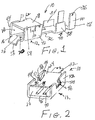
- a modular female electrical terminal 10 has a receptacle portion 12 for receiving a male electrical terminal such as the blade type contact 14 as shown in Figure 5.
- a receptacle portion 12 or interface may have any desired cross-sectional shape adapted to cooperate with any desired male terminal cross-sectional shape, such as for example, pin or blade receiving shapes.
- the receptacle portion 12 comprises a first module 16 which is capable of interfacing with a desired one of a variety of male electrical terminal shapes, such as pin or blade types or other desired shape as are known in the art.
- the first module 16 comprises a base member of the terminal 10 and is formed of a first material having a first thickness.
- the base member 16 preferably provides the principal current flowpath through the female terminal 10. This is preferably accomplished by controlling the thickness or conductivity or both the thickness and conductivity of the base member 16.
- the conductivity of the base member 16 is easily controlled by appropriate selection of the material from which the base member is constructed.
- the second module 18 comprises a cover member.
- the cover member 18 is formed of a second material and has a second thickness.
- the second thickness may be the same as or different from the first thickness. In a particularly preferred embodiment the second thickness is less than the first thickness, since due to the invention, the base member 16 is the principal current path and the cover member 18 does not need to have high current carrying capabilities.
- the cover member 18 is secured to the base member 16 in an overlying relationship.
- the cover member 18 defines in cooperation with the base member 16 a cavity 20 which is suitable for receiving a desired one of the male electrical terminal shapes.
- At least one of the first module or the second module includes a means 24, as for example, the spring element 24 in Figure 2, for biasing the male electrical terminal into electrical and frictional contact with the receptacle portion 12.
- the female electrical terminal 10 is adapted to be mated with a male contact (not shown) at the front end 26 of the terminal 10.
- the rear end 28 of the terminal 10 is adapted to connect the terminal 10 to a conductor (not shown).
- the terminal base member 16 in this embodiment is one-piece member made from sheet metal or other conductive material.
- the base member 16 has a front receptacle portion 12 and a rear conductor connection portion or ferrule 30.
- the front receptacle portion 12 is an open shell or cavity 20 adapted to admit a desired male contact 14 therein.
- the cavity 20 of the receptacle portion 12 of the terminal 10 has a generally rectangular box shaped cross-section. In alternate embodiments, the cavity 20 may have any suitable cross-section to admit a desired male contact shape therein.
- the rear portion of the terminal 28 includes a transition section 32, an intermediate section 34 and a distal section 36.
- the transition section 32 connects the ferrule 30 to the receptacle portion 12 of the terminal 10.
- the intermediate section 34 and the distal section 36 of the ferrule have a general "U" shaped channel configuration.
- the ferrule portion 30 of the terminal 10 is arranged downstream (in the insertion direction) of the receptacle portion 12 and is integrally connected thereto.
- the intermediate section 34 is adapted to receive a conducting core of a conductor (not shown).
- the distal section 36 is preferably somewhat wider than the intermediate section 34 in order to admit a portion of the conductor having insulation thereon.
- Both the intermediate section 34 and the distal section 36 have side compression tabs 38 and 40 respectively.
- the terminal 10 is connected to the conductor by placing the conductor in the ferrule portion 30 and compressing or crimping the tabs 38 and 40 onto the conductor. These side compression tabs 38 are compressed downward around the conducting core of the conductor to crimp the conducting core to the intermediate section 34.
- the side compression tabs 40 on the distal section 36 of the ferrule 30 are pressed downward around the insulated portion of the conductor to crimp the insulated portion to the distal section 36 of the terminal 10.
- a first advantage of this invention is that it is possible to maximize the material thickness of the terminal 10 in the areas where the material is most needed for electrical and mechanical performance.
- the female terminal 10 in accordance with a preferred aspect of this invention allows for a more robust design by allowing the material thickness to be maximized in the areas most needed such as the terminal base 16 where the main current path of the system is preferably provided. It is possible in accordance with this invention to add additional material to the base to increase the current flow and still maintain the same miniaturized packaging size of other terminals. Due to the structure of the contact in accordance with this invention, alternatively or in addition to increasing the thickness of the base it is possible to increase the conductivity of the base member 16 as compared to the cover member 18 by proper selection of the material forming the cover member.
- the cover member 18 can be made from a material having high strength and resiliency such as stainless steel or beryllium copper while the base member 16 can be formed from a higher conductivity copper alloy having sufficient strength for use in a terminal. It is a unique aspect of this invention that the materials which form the respective cover member 18 and base member 16 are formed, may be selected to provide any desired combination of strength and conductivity for each of the modules. Since it is possible to use different materials for each module 16 and 18 a variety of combinations are possible to provide a desired female terminal.
- the base member 16 includes at the receptacle portion 12, side walls 42 and 44 integral therewith, extending towards the cover member 18 so as to form an open cavity 20 which is shaped to receive a desired male electrical terminal 14 shape or any other desired male terminal shape.
- the spring member 24 is stamped from sheet metal or other conductive material. It is possible when using a separate spring member 24 to form it of any desired material which exhibits the desired spring properties. It may be formed from the same or a different material than is used for the respective base member 16' or the cover member 18. For example, it can be formed from a higher strength material which has excellent spring properties such as beryllium copper or any other desired material, irrespective of the material(s) forming the base member 16' or cover member 18.
- the spring 24 preferably has a general leaf-spring type configuration. When viewed from the top plan view, the spring 24 preferably has a substantially rectangular form. Two side tabs 46 project laterally from the longitudinal or curved edges 48 of the spring 24. The side tabs 46 are located generally at the middle or base of the spring 24. The side tabs 46 have an appropriate length and width to be admitted into slots 50 in the side walls 42 and 44 of the receptacle portion 12 when the spring is mounted to the first module or base member 16'. Any desired separate spring member 24 could be employed in accordance with this invention as noted in the patents cited in the background of this invention, which are specifically incorporated by reference herein. Further details of a suitable spring element 24 can also be found in U.S. Application Serial No. 09/124,140 to Roy et al. cross-referenced herein which is also incorporated by reference herein. The spring element 24 is mounted in the base member 16' according to the invention.
- Figure 1 shows the terminal 10 according to a preferred embodiment of the invention.
- the base member 16 comprises further an intermediate part 32 and a front part 12.
- the front part 12 has a generally open box shaped cross section with a bottom 26 and side walls 42, 44.
- the side walls include slot type openings 50, 51 for receiving the spring element 24.
- openings 50 and 51 receive tabs 46 of a spring element 24, such spring element being easily inserted in the openings 50 and 51 due to the structure of the terminal according to the invention.
- the socket part 12 of the terminal according to the invention is closed by a cover 18.
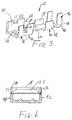
- FIG 4 there is shown a further embodiment of the invention in which the lateral sides 42 and 44 of the front part 12 comprise windows 150 and 151 for receiving the tabs 46 of the spring element 24.
- the spring 24 is inserted in the windows 150 and 151 either by force fitting or during a manufacturing step where the side walls are not totally bent perpendicular to the base 26.
- closing of the box shaped terminal is also done with cover 18 thus keeping with the two part structure of the invention.
- the cover 18 may comprise slots 66 which receive flaps 64 from walls 42 and 44. Flaps 64 are bent on cover 18 in order to mechanically lock the cover 18 on the base 16.
- the cover 18 is of a width allowing it to be received between side walls 42 and 44. Welding sports 58 link the side walls 42 and 44 and the cover 18 together.
- an alternate design provides for the cover to rest on the edges of the side walls 42 and 44 and again the cover is secured to the side walls, which may be done by a welding technique. Both these structures create a strong link between the base 16 and the cover 18 enhancing the stiffness of the box shaped socket part 12 of the terminal 10.
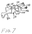
- FIG. 7 Yet a further embodiment of a ferrule portion 130 in accordance with this invention is shown in Figure 7.
- the ferrule portion 130 is different from the previous embodiments in that the intermediate section 134 and the distal section 136 are of the insulation piercing type.
- Opposing blade tabs 180 or 182 extend transversely of the base member 116'' toward one another from the downstream edges 184 and 186 of the respective side tabs 138 and 140 to define respective gaps 188 and 190.
- the conductor (not shown) is pressed into the gaps 188 and 190.
- the gaps 188 and 190 are sufficiently small so that the insulation of the conductor is cut by the blade tabs 180 and 182 which intern engage the conductor to provide an electrical connection thereto.
- the side tabs 138 and 140 may if desired be compressed to clamp the conductor in place.
- This insulation displacement type ferrule 130 can be employed, if desired, with any of the terminal embodiments described heretofore.
- a second advantage is that the cover 18 may be of a light or less conductive material while the base 16 remains of high conductive material.
Landscapes
- Coupling Device And Connection With Printed Circuit (AREA)
Applications Claiming Priority (2)
| Application Number | Priority Date | Filing Date | Title |
|---|---|---|---|
| US09/406,450 US20020055297A1 (en) | 1999-09-27 | 1999-09-27 | Modular female electrical terminal |
| US406450 | 1999-09-27 |
Publications (2)
| Publication Number | Publication Date |
|---|---|
| EP1089388A2 true EP1089388A2 (de) | 2001-04-04 |
| EP1089388A3 EP1089388A3 (de) | 2001-12-19 |
Family
ID=23608048
Family Applications (1)
| Application Number | Title | Priority Date | Filing Date |
|---|---|---|---|
| EP00120234A Withdrawn EP1089388A3 (de) | 1999-09-27 | 2000-09-26 | Modulare elektrische Anschlussbuchse |
Country Status (2)
| Country | Link |
|---|---|
| US (1) | US20020055297A1 (de) |
| EP (1) | EP1089388A3 (de) |
Cited By (1)
| Publication number | Priority date | Publication date | Assignee | Title |
|---|---|---|---|---|
| EP1248318A3 (de) * | 2001-04-07 | 2003-11-19 | BJB GmbH & Co. KG | Elektrischer Kontakt sowie Lampenfassung und Anschluss- oder Verbindungsklemme mit mindestens einem solchen Kontakt |
Families Citing this family (8)
| Publication number | Priority date | Publication date | Assignee | Title |
|---|---|---|---|---|
| US7556541B2 (en) * | 2006-10-06 | 2009-07-07 | Fci Americas Technology, Inc. | Electrical terminal with high conductivity core |
| DE102007016070A1 (de) * | 2007-04-03 | 2008-10-09 | Lear Corp., Southfield | Elektrische Anschlussanordnung und Verfahren zum Nutzen der elektrischen Anschlussanordnung |
| JP4930439B2 (ja) * | 2008-04-04 | 2012-05-16 | 住友電装株式会社 | 端子金具 |
| US10090608B2 (en) | 2016-09-29 | 2018-10-02 | Delphi Technologies, Inc. | Electrical connection system having a terminal with contact ridges |
| CN109149207B (zh) * | 2017-06-28 | 2020-10-30 | 拓自达电线株式会社 | 连接器、电线组件、以及医疗设备用传感器 |
| CN109149145B (zh) | 2017-06-28 | 2020-12-08 | 拓自达电线株式会社 | 压接端子、带压接端子的电线以及医疗设备用传感器 |
| US11387585B2 (en) * | 2020-08-05 | 2022-07-12 | Aptiv Technologies Limited | Anti-fretting/multiple contact terminal using knurl pattern |
| US11646510B2 (en) | 2021-04-29 | 2023-05-09 | Aptiv Technologies Limited | Shielding electrical terminal with knurling on inner contact walls |
Family Cites Families (4)
| Publication number | Priority date | Publication date | Assignee | Title |
|---|---|---|---|---|
| US3370265A (en) * | 1966-05-09 | 1968-02-20 | Berg Electronics Inc | Electrical connector |
| GB2204748B (en) * | 1987-05-15 | 1992-01-15 | Mitsuku Denshi Kogyo | Connection system for connecting wire to circuit element |
| JPH0494275U (de) * | 1991-01-11 | 1992-08-17 | ||
| WO1997049145A1 (de) * | 1996-06-17 | 1997-12-24 | Framatome Connectors International | Steckverbinderhülse |
-
1999
- 1999-09-27 US US09/406,450 patent/US20020055297A1/en not_active Abandoned
-
2000
- 2000-09-26 EP EP00120234A patent/EP1089388A3/de not_active Withdrawn
Cited By (1)
| Publication number | Priority date | Publication date | Assignee | Title |
|---|---|---|---|---|
| EP1248318A3 (de) * | 2001-04-07 | 2003-11-19 | BJB GmbH & Co. KG | Elektrischer Kontakt sowie Lampenfassung und Anschluss- oder Verbindungsklemme mit mindestens einem solchen Kontakt |
Also Published As
| Publication number | Publication date |
|---|---|
| EP1089388A3 (de) | 2001-12-19 |
| US20020055297A1 (en) | 2002-05-09 |
Similar Documents
| Publication | Publication Date | Title |
|---|---|---|
| US6524143B2 (en) | Female crimp terminal | |
| EP1428297B1 (de) | Elektrische Verbinder und Anschlussstück für Starkstrom in Kraftfahrzeugen | |
| US5207603A (en) | Dual thickness blade type electrical terminal | |
| EP0932917B1 (de) | Elektrischer verbinder mit einem gehäuse und einem elektrischen kontaktelement | |
| EP2074681B1 (de) | Elektrischer anschluss mit geschichteten federn | |
| EP0688065B1 (de) | Elektrische Buchse | |
| EP0877390B1 (de) | Elektrische Anschlussbuchse | |
| EP0418698B1 (de) | Elektrischer Anschluss und elektrischer Verbinder mit einem derartigen Anschluss | |
| EP0700124A2 (de) | Elektrischer Kontakt mit verbessertem Verriegelungsteil | |
| KR100248968B1 (ko) | 암형 전기 단자 | |
| US20070099520A1 (en) | Connecting terminal | |
| EP0795930B1 (de) | Elektrische Aufnahmebuchse für Stift mit hoher Kontaktkraft | |
| JP2001210416A (ja) | 端子金具 | |
| EP1089387A2 (de) | Modulare elektrische Anschlussbuchse | |
| EP1089388A2 (de) | Modulare elektrische Anschlussbuchse | |
| EP1935063B1 (de) | Endgerät mit mehrteiliger elektrischer aufnahme | |
| EP0847104B1 (de) | Steckerelement | |
| JP3300251B2 (ja) | 圧接コネクタ | |
| EP0736930A1 (de) | Kontakt mit einem unabhängig unterstützten inneren Kontaktarm | |
| EP1195852B1 (de) | Verbesserungen für Flex-Flachbandkabelanordnungen | |
| EP1199773B1 (de) | Elektrischer Verbinder und Klemme | |
| US11381009B2 (en) | Contact and connector | |
| JP3684319B2 (ja) | 活線挿抜用端子 | |
| JP2537455B2 (ja) | 接続端子 | |
| JPH09293543A (ja) | 電気端子 |
Legal Events
| Date | Code | Title | Description |
|---|---|---|---|
| PUAI | Public reference made under article 153(3) epc to a published international application that has entered the european phase |
Free format text: ORIGINAL CODE: 0009012 |
|
| AK | Designated contracting states |
Kind code of ref document: A2 Designated state(s): AT BE CH CY DE DK ES FI FR GB GR IE IT LI LU MC NL PT SE |
|
| AX | Request for extension of the european patent |
Free format text: AL;LT;LV;MK;RO;SI |
|
| PUAL | Search report despatched |
Free format text: ORIGINAL CODE: 0009013 |
|
| AK | Designated contracting states |
Kind code of ref document: A3 Designated state(s): AT BE CH CY DE DK ES FI FR GB GR IE IT LI LU MC NL PT SE |
|
| AX | Request for extension of the european patent |
Free format text: AL;LT;LV;MK;RO;SI |
|
| RIC1 | Information provided on ipc code assigned before grant |
Free format text: 7H 01R 13/03 A, 7H 01R 13/11 B, 7H 01R 13/187 B, 7H 01R 13/115 B |
|
| AKX | Designation fees paid | ||
| REG | Reference to a national code |
Ref country code: DE Ref legal event code: 8566 |
|
| STAA | Information on the status of an ep patent application or granted ep patent |
Free format text: STATUS: THE APPLICATION IS DEEMED TO BE WITHDRAWN |
|
| 18D | Application deemed to be withdrawn |
Effective date: 20020620 |