EP1089413A2 - Limiteur de courant - Google Patents
Limiteur de courant Download PDFInfo
- Publication number
- EP1089413A2 EP1089413A2 EP19990203423 EP99203423A EP1089413A2 EP 1089413 A2 EP1089413 A2 EP 1089413A2 EP 19990203423 EP19990203423 EP 19990203423 EP 99203423 A EP99203423 A EP 99203423A EP 1089413 A2 EP1089413 A2 EP 1089413A2
- Authority
- EP
- European Patent Office
- Prior art keywords
- current
- current limiter
- value
- processing unit
- control
- Prior art date
- Legal status (The legal status is an assumption and is not a legal conclusion. Google has not performed a legal analysis and makes no representation as to the accuracy of the status listed.)
- Withdrawn
Links
Images


Classifications
-
- H—ELECTRICITY
- H02—GENERATION; CONVERSION OR DISTRIBUTION OF ELECTRIC POWER
- H02H—EMERGENCY PROTECTIVE CIRCUIT ARRANGEMENTS
- H02H3/00—Emergency protective circuit arrangements for automatic disconnection directly responsive to an undesired change from normal electric working condition with or without subsequent reconnection ; integrated protection
- H02H3/08—Emergency protective circuit arrangements for automatic disconnection directly responsive to an undesired change from normal electric working condition with or without subsequent reconnection ; integrated protection responsive to excess current
-
- H—ELECTRICITY
- H01—ELECTRIC ELEMENTS
- H01H—ELECTRIC SWITCHES; RELAYS; SELECTORS; EMERGENCY PROTECTIVE DEVICES
- H01H71/00—Details of the protective switches or relays covered by groups H01H73/00 - H01H83/00
- H01H2071/006—Provisions for user interfaces for electrical protection devices
-
- H—ELECTRICITY
- H02—GENERATION; CONVERSION OR DISTRIBUTION OF ELECTRIC POWER
- H02H—EMERGENCY PROTECTIVE CIRCUIT ARRANGEMENTS
- H02H11/00—Emergency protective circuit arrangements for preventing the switching-on in case an undesired electric working condition might result
Definitions
- the invention relates to a current limiter and in particular to a current limiter intended to be used as a protection against taking too much current from an available supply mains. This is especially important in those cases in which one has no direct control over the safety fuses incorporated in the supply mains, such as is generally the case on camping sites.
- the maximum power allowed to be used per caravan may be different for each camping site, in which practice has shown that these differences are considerable. This can result in the fact that on one camping site will have largely enough power available on the supply mains of said camping site for use of apparatus connected in the caravans and that with the same power consumption on a next camping site the safety fuses of the camping site owner will melt. Apart from the fact that it's a nuisance that the safety fuses of the camping site owner melt and the camping site owner must be asked to replace the fuses, in practice it may be troublesome to have them replaced immediately, definitely when the fuses melt in the evening or at night.
- the object of the invention is to remove said disadvantages and to provide current limiter which is adjustable and is capable of interrupting the presented voltage quickly enough.
- the current limiter is at least provided with means for detecting the current acquired, a control/processing unit for comparing the current acquired with a value to be set within a certain range, and further means for interrupting the voltage presented when the current acquired is higher than the set value.
- the means for detecting the current acquired comprise at least one coupling member which is to be coupled inductively to the presented supply mains, control means having been provided for carrying out a predetermined number of measurements within a predetermined period of time.
- the measurements can consist of e.g. sequences of 200 successive measurements carried out at a frequency of 2 kHz.
- the total measuring time per sequence will then be 100 msec, which at a mains frequency of 50 Hz will mean that the measurements are divided over 5 periods. If between successive sequences of measurements an equal time is maintained in which one sequence of measurements is carried out, then every second 5 sequences of measurements, 1000 measurements in all, will be carried out.
- control/processing unit is arranged such that for each predetermined period of time the effective value or a quantity proportional to it, of the values measured in that period of time is calculated.
- the effective value can be calculated by e.g. taking the root from the average of the squares of the 200 measured currents in a sequence. By determining a mean effective value across such a number of measurements prevents incidental short changes in current intensity from being decisive for whether or not switching-off the presented voltage.
- the measuring time and the subsequent switching time for interrupting the current is amply within the melting time of a normal, slow fuse for the supply mains.
- input means are connected to the control/processing unit, by means of which the value to be set can be set in one or more sequences of stages within the determined range, in which at the same time it has been provided for, that first read out means are connected to the control/processing unit, by means of which at least the set value can be read out.
- a simple embodiment provides for that two pressure switches have been mounted on a control panel, in which the value to be set can be increased in stages with a first button and it can be decreased in stages with a second button.
- the control/processing unit can be set such, that in a range of e.g. 1 - 16A, in the lowermost part of the range the stages each represent 0,5A, and in the uppermost part of the range the stages each represent 1A.
- the first read out means which can consist of a simple 2-digit display, indicate the stepwise changing of the value to be set and the finally set value.
- second read out means connected to the control/processing unit have been provided, which indicate the course of the detected acquired current or an effective value calculated from it in time, the second read out means consisting of a row of successive signal emitters and the control/processing unit is arranged to divide the set value in as many ranges as there are signal emitters and to drive the signal emitter concerned for a detected value or a calculated effective value.
- the signal emitters are designed as a series of LEDs mounted in a vertical row, so that with an increasing current, an LED situated increasingly higher in the row will light up. Since the driving of the LEDs is determined anew for each newly set maximum usable current, the visual information for each set value indicated by the LEDs always gives the same ratio number in relation to the maximum allowed consumption.
- the visual information can be improved further by mounting LEDs having different colours, in which a number of the upper LEDs might emit e.g. red light.
- control/processing unit When exceeding the set value, the control/processing unit will determine that the detected current or the effective value calculated from it is higher than the set value and the presented voltage will be interrupted.
- a simple and reliable circuit for this purpose which is furthermore additionally resistent against temporary high currents, is a circuit having a relay.
- control/processing unit is arranged such that when said control/processing unit interrupts the presented voltage, at least an acoustic signal will be emitted. This is desirable since it will not always be clear that the voltage presented has been interrupted by the current limiter. In addition, it is also possible to produce a signal through the LEDs, e.g. by having them flash.
- the current limiter provides for that every time the current consumption exceeds a set value, the voltage will be interrupted.
- the current limiter discussed thus far will likewise interrupt the presented voltage.
- the control/processing unit is arranged such that with an acquired current higher than a predetermined maximum value, in which the predetermined maximum value is higher than the highest value that can be set within the specific range, the presented voltage will not be interrupted.
- a second inductive coupling particularly intended for detecting short-circuit currents.
- a number of measurements can be carried out at a specific frequency, and a value calcultated from them can be compared to the maximum value. Since short-circuit currents quickly achieve a high value, which is far beyond the melting current of a fuse, the sampling period can be shorter than the period during which the first inductive coupling is used for sampling.
- the logic result signals of the comparisons of measured values or values calculated from them, coming from both inductive couplings with the set value and the maximum value, carried out in the control/processing unit, can be supplied to a simple logic OR-circuit, in which the resultant will decide whether or not the relay will be excited.
- control/processing unit is arranged such that when connecting the current limiter to the supply mains, the value to be set within a specific range is set to a predetermined low value, which will be at least sufficient for feeding the current limiter. Through this, it can be prevented that on connecting the caravan to the supply mains the current limiter is still set to a value for a previous camping site, which may be too high.
- Fig. 1 illustrates schematically the design of the current limiter 1, consisting of a part 2 where the neutral and phase wires 3, 4 of a presented supply mains and a ground wire 5 enter and a control/processing unit 6.
- the neutral and phase wires 3, 4 incorporate a relay 7 being driven from said control/processing unit 6.
- the neutral and phase wires contain fuses 8, 9, in this case the fuses owned by the provider of the supply mains.
- control/processing unit 6 The supply for control/processing unit 6 is acquired from the neutral and phase wires 3, 4, a fuse 12 being incorporated in line 11, and is supplied to transformer 13. Through a rectifier and stabilizing cicuit not further illustrated, the required voltage can be supplied to control/processing unit 14.
- a current detector 15 is mounted around a wire of the presented supply mains and connected to an input of the control/processing unit 14.
- the current detector can consist of a coil and an amplifier, in which the detected current can be supplied to said control/processing unit 14 as a voltage level correlated to it.
- a second coil is provided, by means of which short-circuit currents can be detected.
- Relay 7 is driven through an outlet of the control/processing unit 14 dependent on the detected current.
- Two further outlets drive, respectively, a read out member 16 indicating the set maximum current to be consumed and a further read out member 17 indicating the course of the measured current or its calculated effective value.
- buttons 18, 19, 20 is mounted at the input side of the control/processing unit 14, push button 18 being intended for switching in the current limiter again after the voltage was interrupted in reaction to a consumption which was too high.
- the push buttons 19 and 20 are intended to set the maximum current upwards or downwards, respectively.
- the line 21 has made a division between an upper part and a lower part, with the situation in the upper part being such that it does not allow any interruptions, as they occur with making settings or driving read out members with new values, and it only allows setting and initializing the current limiter anew.
- the diagram is further divided in vertical columns, in which the columns 22 and 23, illustrate the interruptions with high priority and low priority, respectively.
- the interruptions with high priority given in column 22 concern setting the maximum consumable current, passing the set value on to the control/processing unit 14 and driving the read out member 16 from there.
- Column 23 indicates the low priority interruptions, which concern transformation of the measured current, determining which LED of read out member 17 should be driven, and driving the LED concerned.
- Column 24 contains the most essential parts of the software, such as measuring the current and calculating the effective value, comparing it to the set maximum value and on exceeding said value, de-energizing the relay 7 and passing on an error message. Passing on the error message can consist of e.g. a step in which a symbol corresponding to an error message is reproduced on the read out member 16 and a step in which an acoustig signal is emitted.
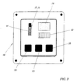
- Fig. 3 illustrates a simple embodiment of a possible front 30 for the relatively small housing in which the complete current limiter can be incorporated.
- Push buttons 18, 19, 20 are mounted in a row in het lower part, button 18 serving for setting the current limiter anew, and buttons 19, 20 for adjusting the setting of the maximum consumable current upwards and downwards, respectively.
- the first button 18 can be given a dual function, in which the second function can only be used when the current limiter is in operation.
- the second function is preferably switching off the read out members 16, 17, by which at night the possibly inconvenient light of the read out members can be switched-off.
- Read out member 16 can display two figures with or without decimal point, so that settings below 10A can be displayed in decimals and settings above it only in integrals.
- Read out member 17 comprises 10 LEDs 31 mounted one above the other in a row, which can be chosen such that successive parts of the range show different colors, in which e.g. the upper three LEDs can emit red light as a warning sign. Finally, a member 32 has been provided for emitting an acoustic warning signal when the set current is exceeded.
Landscapes
- Emergency Protection Circuit Devices (AREA)
Applications Claiming Priority (2)
| Application Number | Priority Date | Filing Date | Title |
|---|---|---|---|
| NL1013114A NL1013114C1 (nl) | 1999-09-22 | 1999-09-22 | Stroombegrenzer. |
| NL1013114 | 1999-09-22 |
Publications (1)
| Publication Number | Publication Date |
|---|---|
| EP1089413A2 true EP1089413A2 (fr) | 2001-04-04 |
Family
ID=19769919
Family Applications (1)
| Application Number | Title | Priority Date | Filing Date |
|---|---|---|---|
| EP19990203423 Withdrawn EP1089413A2 (fr) | 1999-09-22 | 1999-10-19 | Limiteur de courant |
Country Status (2)
| Country | Link |
|---|---|
| EP (1) | EP1089413A2 (fr) |
| NL (1) | NL1013114C1 (fr) |
-
1999
- 1999-09-22 NL NL1013114A patent/NL1013114C1/nl not_active IP Right Cessation
- 1999-10-19 EP EP19990203423 patent/EP1089413A2/fr not_active Withdrawn
Also Published As
| Publication number | Publication date |
|---|---|
| NL1013114C1 (nl) | 2001-03-23 |
Similar Documents
| Publication | Publication Date | Title |
|---|---|---|
| FI80816C (fi) | Datastyrd kopplingsanordning. | |
| EP0634825B1 (fr) | Module déclencheur contre les surintensités avec indication de la dépendance des fonctions de déclenchement | |
| KR970029957A (ko) | 전기 스위칭 장치 및 이용자 인터페이스를 전기 스위칭 장치에 제공하는 방법 | |
| CA2109258A1 (fr) | Dispositif interrupteur de circuit electrique | |
| JPH0363298B2 (fr) | ||
| JPS63247668A (ja) | 電圧レベル判別装置 | |
| KR101740201B1 (ko) | 오시공 방지기능이 탑재된 전원용 서지보호기 및 오시공 판단방법 | |
| EP1089413A2 (fr) | Limiteur de courant | |
| US3424919A (en) | Remote control system for electrical apparatus | |
| EP1368997B1 (fr) | Appareil electrique et procede correspondant | |
| WO2004042761A1 (fr) | Dispositif de commutation miniature | |
| KR19980019587U (ko) | 이상전압보호기능을 갖는 전원공급장치 | |
| CN107408807B (zh) | 保护装置 | |
| KR100254699B1 (ko) | 누전차단기 | |
| JP3230283U (ja) | コードリール | |
| JP3291360B2 (ja) | イコライザ装置 | |
| KR970008369B1 (ko) | 과전압 보호 및 표시장치 | |
| KR0141814B1 (ko) | 전자식 배선차단기의 과부하 경보방법 및 장치 | |
| KR100833374B1 (ko) | Pdp-tv의 a/v보드 인식 표시장치와 방법 | |
| KR100883043B1 (ko) | 차단기의 과열 알림 장치 | |
| JPH0963706A (ja) | 電流モニタ付コンセント | |
| KR200263732Y1 (ko) | 저가형 변압기 과부하 감지기 | |
| KR100295906B1 (ko) | 전자식전원차단장치의샘플링주파수및경보신호선택회로및방법 | |
| JPH05334952A (ja) | 回路遮断器 | |
| KR950009807Y1 (ko) | 집합형 전기화재 경보기 |
Legal Events
| Date | Code | Title | Description |
|---|---|---|---|
| PUAI | Public reference made under article 153(3) epc to a published international application that has entered the european phase |
Free format text: ORIGINAL CODE: 0009012 |
|
| AK | Designated contracting states |
Kind code of ref document: A2 Designated state(s): AT BE CH CY DE DK ES FI FR GB GR IE IT LI LU MC NL PT SE |
|
| AX | Request for extension of the european patent |
Free format text: AL;LT;LV;MK;RO;SI |
|
| STAA | Information on the status of an ep patent application or granted ep patent |
Free format text: STATUS: THE APPLICATION IS DEEMED TO BE WITHDRAWN |
|
| 18D | Application deemed to be withdrawn |
Effective date: 20011101 |