EP1090577B1 - Distributeur - Google Patents
Distributeur Download PDFInfo
- Publication number
- EP1090577B1 EP1090577B1 EP00308892A EP00308892A EP1090577B1 EP 1090577 B1 EP1090577 B1 EP 1090577B1 EP 00308892 A EP00308892 A EP 00308892A EP 00308892 A EP00308892 A EP 00308892A EP 1090577 B1 EP1090577 B1 EP 1090577B1
- Authority
- EP
- European Patent Office
- Prior art keywords
- plate
- bottle
- reservoir
- mounting
- pair
- Prior art date
- Legal status (The legal status is an assumption and is not a legal conclusion. Google has not performed a legal analysis and makes no representation as to the accuracy of the status listed.)
- Expired - Lifetime
Links
Images








Classifications
-
- A—HUMAN NECESSITIES
- A47—FURNITURE; DOMESTIC ARTICLES OR APPLIANCES; COFFEE MILLS; SPICE MILLS; SUCTION CLEANERS IN GENERAL
- A47K—SANITARY EQUIPMENT; ACCESSORIES THEREFOR, e.g. TOILET ACCESSORIES
- A47K5/00—Holders or dispensers for soap, toothpaste or the like
- A47K5/06—Dispensers for soap
- A47K5/12—Dispensers for soap for liquid or pasty soap
- A47K5/1202—Dispensers for soap for liquid or pasty soap dispensing dosed volume
- A47K5/1204—Dispensers for soap for liquid or pasty soap dispensing dosed volume by means of a rigid dispensing chamber and pistons
Definitions
- This invention relates to a system for dispensing soap with a wide range of viscosities.
- soap will be used for only illustrative purposes.
- soap is dispensed in commercial systems wherein the soap has a relatively low viscosity in the order of 1000 to 2000 cps.
- the present invention is directed toward a system which can accommodate the lower viscosity soaps normally encountered in commercial establishments such, as restaurants, washrooms, airports, and the like, as well as grit containing soaps in which the viscosities may be as high as 20,000 cps. (see e.g. US-A-3,540,630)
- Patents which are relevant to the lower viscosity dispensing systems include but are not limited to U.S. patent nos. Des. 248,927, Des. 278,887, Des. 282,347, Des. 282,528, Des. 299,427, Des. 325,312, Des. 332,544, 4,149,573, 4,173,858, 4,214,676, 4,316,555, 4,391,308, 4,391,309, 4,429,812, 4,673,109; 4,886,192, 5,082,150, 5,174,476, 5,209,377 4,345,627, and 4,576,313.
- Yet another object of the present invention is to provide a device in which a high viscosity liquid can be dispensed in doses using a standard dispensing mechanism.
- Yet another object of the present invention is to provide a combination soap to be dispensed while at the same time retaining the sealing material used to seal the soap cartridge attached to the soap cartridge so as to prevent inadvertent plugging of the dispensing mechanism.
- Another object of the present invention is to provide a series of mounting plates useful for mounting a variety of combinations of the various constituent parts of,the liquid dispensing system.
- a still further object of the present invention is to incorporate a new soap container or bottle which can be mated to a backing or mounting plate so as to provide a commercially secure system.
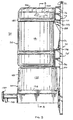
- a soap dispensing system 50 which includes a soap bottle or container 55 sitting on top of a reservoir 60 which is received by a dispensing mechanism 65, all of which are supported by a support plate 70.
- a support plate 70 Various plate configurations are disclosed hereinafter which support various combinations of the components described above.
- the support plate 70 includes a generally rectangular member 71 having a front surface 72 and a rear surface 74 and having a plurality of mounting apertures 73 therein.
- the mounting apertures 73 are at each ends of the plate 71 and also longitudinally spaced from but near the bottom of the plate 71.
- a first pair of mounting tracks or rails 75 is positioned near the top of the support plate 70 and each rail 75 includes an inwardly directed, generally rectangular plate 76 having top and bottom triangularly shaped end ribs 77 and an intermediate triangularly shaped reinforcing member 78.
- a plurality of strengthening ribs 81 on the inwardly facing surfaces of the plate 76 help to stabilize the first pair of mounting rails 75.
- first or upper shelf 85 which includes a platform 86 which extends somewhat downwardly from the edges of the platform toward the middle, as best seen in Fig. 17, as will be explained later, the platform 86 being provided with a plurality of outwardly extending ribs 87 and a number of triangular supports 88, there being three shown.
- An upper latch 90 extends outwardly from the surface 72 of the plate 70 and includes a generally rectangular or square flap 91 extending outwardly from an opening 92 in the plate 70 and being connected to the plate by a hinge 93 so that the flap is movable by flexing or pivoting about the hinge 93.
- a second pair or lower mounting tracks or rails 95 each of which includes a generally flat rectangular plate 96 extending inwardly and outwardly from the plate 70 and more particularly the front surface 72 thereof being provided with end plates 97 similar to the end plates 77 previously described and a middle reinforcing member 98 similar to the previous reinforcing member 78 hereinbefore described.
- the inner sides of the plates 96 include a plurality of ribs 101.
- a second or lower shelf 105 which is a generally flat piece having an upper surface 106 and a curved arcuate outwardly facing edge 107.
- a plurality of support ribs 108 at the bottom of the shelf 105 are seen in Figs. 17, 19 and 20.
- a receiving mechanism 115 for the dispenser mechanism 65 includes two generally vertically positioned and slightly tapered toward each other and spaced apart L-shaped channels 116 each of which is strengthened by a plurality of generally horizontally extending ribs 117 and a support ledge 120 generally horizontally extending and having in L-shaped portion or channel 121 with a plurality of downwardly extending supports 122.
- the tapering of the channels 116 results in a wedging of the dispensing mechanism 65.
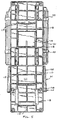
- the rear of the plate 70 is provided, as seen particularly in Fig. 5, with a plurality of horizontal and vertical ribs 118 and 119, respectively, for strengthening purposes.
- the dispensing mechanism 65 includes a dispensing mechanism support structure 125 which includes a flat circular plate 126 having a rectangular cut-out slot 127 therein and an upstanding peripheral ridge or flange 128. A plurality of circular segments 129 extend upwardly from the plate 126 for a purpose hereinafter set forth. A ball check valve 130 is positioned in the central circular cut-out contiguous with the slot 127.
- a horizontal ledge 131 Extending rearwardly integrally with the dispensing mechanism support plate 125 is a horizontal ledge 131 having a vertical plate 132 provided with a plurality of mounting apertures 133.
- the vertical plate 132 extends downwardly and fits within the two opposed and tapered L-shaped side channels 116 so as to mount the dispensing mechanism 65 by wedging and centring action to the plate 70 as illustrated in Fig. 4 or to plate 70C as illustrated in Fig. 9.
- Plate 70C is substantially the same as the lower portion of the plate 70 previously described from a horizontal point just above the lower latch 110 to the bottom of the support plate.
- Like numbers have been used to identify like portions of the two plates 70 and 70C.
- the actuator 135 further includes an actuator housing 139 which surrounds the slot 127 and the ball check valve 130 and provides support for the actuator 135, the dispensing mechanism 165 in general being of old design and well known in the art.
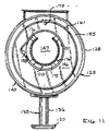
- the reservoir 60 has a frustoconical reservoir housing 145 having a flat upper surface 146 and a flat bottom surface 147.
- the flat bottom surface 147 is provided with a plurality of circular arcuate indentations 149 in the bottom thereof which fit over and frictionally fit upon the wedging segments 129 in the plate 126 of the dispensing mechanism support plate 125.
- An outer wall 155 extends from the bottom 147 up to the top surface 146 defining an aperture 157 in the middle.
- a notch 158 which may identify a docking lug position, is cut into one side of the top wall 146 and may be located in one of eight different angular positions, for a purpose hereinafter set forth.
- the circular ledge 161 extends upwardly from the upper surface 146 to receive the bottle 55, as will be described.
- a window 159 is provided in the front of the side wall 155 to permit the operator to view the soap level in the reservoir 60 at any particular time.
- a cylindrical skirt 163 extends downwardly from the top wall 146 and is provided with a plurality of circumferentially spaced apart notches or cut-outs 164 to facilitate soap flow, as will be explained.
- the skirt 163 defines a well 165 in which is positioned a C-shaped punch mechanism 170.
- the C-shaped punch mechanism 170 is intended to puncture a membrane or seal in the neck of a soap bottle 55 when the latter is positioned on top of the reservoir 60.
- the punch mechanism includes an upwardly extending cylindrical wall 171 also provided with a plurality of circumferentially spaced apart notches or cut-outs 172, also to facilitate flow of soap.
- the C-shaped punch 170 has an angular extent of not less than about 270° and preferably about 295° and is provided at the top end thereof with a plurality of serrated teeth 175.
- Connecting struts 176 circumferentially spaced around the C-shaped punch 170 connect the cylindrical wall 171 to the skirt 163.
- a drain hole 179 is provided at the bottom of the surface 146 to facilitate cleaning of the reservoir structure 60.
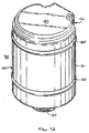
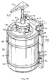
- a soap bottle body 180 similar to that disclosed in Fig. 1 and labelled 55.
- the soap bottle of Fig. 1 and the soap bottle of Figs. 12 through 15 are principally the same and like numbers will be used to describe like portions.
- a bottle body 180 is generally cylindrical in shape and has a side wall 181 closed by a top wall 182 from the bottom wall 183 of the bottle 180 with the distal end of the neck 185 being in the form of plurality of ridges 186. In some circumstances, the ridges 186 may be threads, as will be described.
- the neck 185 includes a cylindrical portion 187 from which protrudes a lug 188 complimentary in shape to the notch 158 in the reservoir 60.
- the lug 188 may be positioned in eight various angularly disposed positions to accommodate systems which are proprietary to each purchaser. Moreover, a plurality of lugs and notches may be used to create more proprietary systems; and the lugs and notches may be reversed with the notch bottle neck. Finally, longitudinally spaced apart cylindrical bands 189 serve to rigidify the bottle 180.
- the upper dove tail member 190 is configured to fit as a tongue and groove fit into the upper mounting rails 75 and the lower dove tail member 195 is spaced to fit into the lower mounting rails 95.
- the upper dove tail member 190 includes a back wall 191 and spaced side walls 192 extending rearwardly of the container or bottle 55.
- a protuberance 193 extends downwardly from the rearward and bottom portion of the upper dove tail member 190.
- the lower dove tail member 196 has a back wall, opposed side walls 197 and a protuberance 197 which extends upwardly toward the protuberance 198.
- plate 70B there is an intermediate sized plate 70B on which like numbers are used to identify like parts.
- the lower shelf in the embodiment of plate 70B is somewhat differently shaped to the shelf in the embodiment 70 and is identified as 105B because it is trapezoidal in shape and has a longer perpendicular extent than does the arcuately shaped embodiment 70 shelf. The purpose of this will hereinafter be set forth.
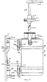
- FIG. 18-20 there is disclosed an embodiment 210 which is a combination of the plate 70B, the soap bottle 55 and a dispensing mechanism as is well known in the art and is akin to that used on condiments such as mustard jars in restaurants and the like.
- the mounting plate 70B was previously described as was the soap container 55 on which like numbers have been applied to like parts.
- the soap container 55 slides into the upper and lower mounting rails 75 and 95, respectively, as previously described and the latch mechanism 90, as seen in Fig. 19, contacts the top of protuberance 198 and serves to maintain the soap container or bottle 55 in place preventing removal by the users of these dispensers in commercial and industrial locations.
- the embodiment 210 includes a circular cap 211 having an internally threaded portion 212 which mates with external threads on the neck 187 of the soap container 55.
- a sleeve 213 extends vertically through the cap 211 and receives a tube 215 which extends into the soap bottle 55 and the soap 220 disposed therein and can create a suction in the usual manner to dispense soap through the tube 215 and out the spout 216, all in a well known manner.
- a variety of features of the present invention are important. Among the most important features are the means by which the upper latch 90 contacts the protuberance on the spaced apart dove tail members 190, 195 and particularly the lower protuberance 198 so as firmly to clamp the soap bottle or container 55 onto the mounting plate 70.
- the lower latching mechanism 110 slips over the top of the vertical wall 132 securely to fasten the dispensing mechanism 65 which includes the actuator 135 and dispensing mechanism support plate 125 firmly to the mounting plate 70. Whether the mounting plate 70, 70B or 70C is used, the connections are substantially the same. The virtues of this system are that it is easy in the field to use, the mechanism is easy to maintain and lends itself to a variety of uses.
- Soaps with yield values above 120 can be dispensed with the system of the present invention and this includes soaps having viscosities in the neighbourhood of 20,000 cps.
- Yield value is a property critical to achieving certain physical characteristics such as particles dispersed in a suspension, emulsions, foams and the like.
- yield value is the Brookfield yield value extrapolation method.
- a Brookfield RVT viscometer is used to measure the torque necessary to rotate a spindle through a liquid sample at speeds of 0.5 to 100 rpm. Multiplying the torque reading by the appropriate constant for the spindle and speed gives the apparent viscosity. Spindle speed corresponds to shear rate. Yield value is an extrapolation of measured values to a shear rate of zero.
- Viscous suspensions can and will collapse. It is a common misconception that if the viscosity of a product is high enough, it can be used to suspend. Actually, a higher viscosity only slows down the rate of particle movement. Yield value is required to create a stable suspension.
- Silica sand with an average particle diameter of 0.6 mm was placed in gels made from various thickener types at different concentrations. The data suggests that a critical Brookfield yield value between 90 and 124 is required to produce a stable sand suspension.
- the system of the present invention has been capable of adequately dispensing samples having viscosities of 13,000 cps and a yield value of 980, viscosities of 7500 cps with a yield value of 520 and soaps with viscosities of 20,500 cps having a yield value of 1540.
- the subject system is entirely capable of dispensing soaps having a wide range of yield values and viscosities since it is also just as clear that the system can also effectively dispense soaps having very low viscosities in the 1000-2000 cps range.
Landscapes
- Health & Medical Sciences (AREA)
- Public Health (AREA)
- Containers And Packaging Bodies Having A Special Means To Remove Contents (AREA)
- Closures For Containers (AREA)
- Fats And Perfumes (AREA)
Claims (16)
- Plaque de montage (70) et réservoir (60) et mécanisme de distribution (65) à utiliser avec une bouteille (55) contenant un liquide présentant une viscosité allant jusqu'à environ 20 000 cps, ladite plaque de montage (70) présentant une surface rectangulaire sensiblement plate (72), une première paire de pistes de montage (75) s'étendant vers l'extérieur de ladite surface (72), une première tablette (85) positionnée essentiellement horizontalement et s'étendant vers l'extérieur de ladite surface (72) essentiellement en dessous et entre ladite première paire de pistes (75), une deuxième paire de pistes de montage (95) s'étendant vers l'extérieur de ladite surface (72) verticalement espacée en dessous de ladite première paire de pistes de montage (75), une deuxième tablette (106) positionnée essentiellement horizontalement et s'étendant vers l'extérieur de ladite surface (72) essentiellement en dessous et entre ladite deuxième paire de pistes (95), caractérisée par un verrou supérieur mobile (90) s'étendant vers l'extérieur de ladite surface (72) essentiellement positionné entre ladite première tablette et ladite deuxième paire de pistes (75 et 95), et un mécanisme de fixation et de verrou inférieur (110, 115) en dessous de ladite deuxième tablette (106) pour supporter un mécanisme de distribution de liquide, une bouteille (55) présentant un col (185) à une extrémité de celle-ci comportant une membrane pouvant être perforée, ladite bouteille comportant un élément en queue d'aronde (190; 195) s'étendant longitudinalement à la bouteille et espacé pour coulisser entre au moins une desdites première et deuxième paires de pistes de montage (75; 95) sur ladite plaque de montage (70), ledit réservoir (60) comprenant une enceinte (145) présentant une extrémité destinée à recevoir la bouteille de liquide, et comportant une ouverture (151) à l'autre extrémité à travers laquelle le liquide s'écoule, ladite enceinte de réservoir comportant un poinçon (170) s'étendant vers le haut dans celle-ci et positionné pour s'étendre dans le col de la bouteille et pour perforer la membrane, ledit poinçon (170) présentant une surface de coupe supérieure (175) sous la forme d'un cercle partiel pour perforer la membrane tout en laissant la membrane attachée à la bouteille, ledit poinçon présentant une étendue courbe non inférieure à environ 270°, un mécanisme de distribution (65) comprenant une plaque (126) destinée à recevoir l'autre extrémité dudit réservoir, ladite plaque de distribution (126) comportant une ouverture (127) en communication avec ladite ouverture (151) dans l'autre extrémité dudit réservoir, un actionneur (135) monté sur ladite plaque de distribution (126) et en communication avec l'autre extrémité dudit réservoir pour distribuer des doses individuelles de liquide à partir dudit réservoir lors de l'actionnement manuel dudit actionneur, et un mécanisme de verrouillage (129) pour connecter à affleurement ledit réservoir et ledit mécanisme de distribution.
- Dispositif selon la revendication 1, dans lequel ladite plaque de montage (70) comporte une pluralité d'ouvertures de montage (73).
- Dispositif selon la revendication 1 ou 2, dans lequel les pistes de montage de ladite première paire de pistes de montage s'étendant verticalement (75) sont inclinées vers l'intérieur l'une vers l'autre.
- Dispositif selon la revendication 1, 2 ou 3, dans lequel ladite première tablette (85) présente deux extrémités extérieures, chaque extrémité étant positionnée à proximité d'une desdites premières pistes de montage, ladite première tablette s'étendant vers le bas à partir de chaque extrémité extérieure en direction du milieu de ladite première tablette.
- Dispositif selon l'une quelconque des revendications précédentes, dans lequel chacune de ladite première paire de pistes de montage (75) et de ladite première tablette (85) comporte des nervures de renforcement moulées sur celles-ci.
- Dispositif selon l'une quelconque des revendications précédentes, dans lequel ladite deuxième tablette (106) présente un bord distal écarté de ladite plaque et de forme courbe.
- Dispositif selon l'une quelconque des revendications précédentes, dans lequel ledit verrou supérieur (90) est intégré à ladite plaque (70).
- Dispositif selon l'une quelconque des revendications précédentes, dans lequel ladite plaque (70) comportant lesdites première et deuxième paires de pistes de montage (75 et 95), lesdites première et deuxième tablettes (85 et 106), ledit verrou supérieur (90) et ledit mécanisme de fixation et de verrou inférieur (110) constituent une seule pièce de matière plastique.
- Dispositif selon l'une quelconque des revendications précédentes, dans lequel ladite bouteille (55) comprend deux éléments en queue d'aronde longitudinalement espacés (190, 195) pouvant coulisser entre lesdites première et deuxième paires de pistes de montage (75, 95) sur ladite plaque (70) lorsque ladite bouteille est montée sur ladite plaque.
- Dispositif selon la revendication 9, dans lequel lesdits premier et deuxième éléments en queue d'aronde (190 et 195) entrent respectivement en contact avec lesdites première et deuxième tablettes (85 et 106) lorsque ladite bouteille est montée sur ladite plaque (70).
- Dispositif selon la revendication 10, dans lequel ledit verrou supérieur (90) s'étend au-dessus d'un desdits éléments en queue d'aronde (195) lorsque ladite bouteille (55) est montée sur ladite plaque (70) pour verrouiller ladite bouteille sur ladite plaque.
- Dispositif selon l'une quelconque des revendications précédentes, dans lequel ladite enceinte de réservoir (145) est tronconique avec des surfaces supérieure et inférieure circulaires plates (146 et 147), la surface supérieure (146) présentant un diamètre plus petit que la surface inférieure (147), ladite surface supérieure comportant une ouverture essentiellement circulaire, ladite surface de coupe supérieure (175) du poinçon comportant des dents de scie et étant positionnée en dessous de ladite surface supérieure (146), lesdites dents de scie s'étendant en direction de la surface supérieure.
- Dispositif selon la revendication 12, dans lequel ledit réservoir comprend en outre une jupe (163) s'étendant vers le bas à partir de ladite surface supérieure et étant essentiellement concentrique avec ledit poinçon (170).
- Dispositif selon la revendication 13, dans lequel ladite jupe de réservoir (163) est essentiellement cylindrique et présente une pluralité de parties (164) qui ont été enlevées pour faciliter l'écoulement.
- Dispositif selon la revendication 12, 13 ou 14, dans lequel les dents de scie s'étendent d'une façon courbe sur environ 295°.
- Dispositif selon l'une quelconque des revendications précédentes, dans lequel ledit mécanisme de fixation et de verrou (110) verrouille ledit mécanisme de distribution (65) sur ladite plaque de montage (70).
Applications Claiming Priority (2)
| Application Number | Priority Date | Filing Date | Title |
|---|---|---|---|
| US09/415,773 US6321943B1 (en) | 1999-10-09 | 1999-10-09 | Soap dispenser for soap of different viscosity |
| US415773 | 1999-10-09 |
Publications (3)
| Publication Number | Publication Date |
|---|---|
| EP1090577A2 EP1090577A2 (fr) | 2001-04-11 |
| EP1090577A3 EP1090577A3 (fr) | 2002-04-03 |
| EP1090577B1 true EP1090577B1 (fr) | 2006-03-15 |
Family
ID=23647136
Family Applications (1)
| Application Number | Title | Priority Date | Filing Date |
|---|---|---|---|
| EP00308892A Expired - Lifetime EP1090577B1 (fr) | 1999-10-09 | 2000-10-09 | Distributeur |
Country Status (5)
| Country | Link |
|---|---|
| US (2) | US6321943B1 (fr) |
| EP (1) | EP1090577B1 (fr) |
| AT (1) | ATE320210T1 (fr) |
| CA (1) | CA2322739C (fr) |
| DE (1) | DE60026671D1 (fr) |
Families Citing this family (29)
| Publication number | Priority date | Publication date | Assignee | Title |
|---|---|---|---|---|
| US6543651B2 (en) | 2000-12-19 | 2003-04-08 | Kimberly-Clark Worldwide, Inc. | Self-contained viscous liquid dispenser |
| US20020117233A1 (en) * | 2001-02-27 | 2002-08-29 | Kellogg Matthew Kenyon | Disposable/reusable lubrication container system |
| US6540117B2 (en) | 2001-03-30 | 2003-04-01 | Kimberly-Clark Worldwide, Inc. | Dosing pump for liquid dispensers |
| US7066356B2 (en) * | 2002-08-15 | 2006-06-27 | Ecolab Inc. | Foam soap dispenser for push operation |
| US7156353B2 (en) | 2003-07-25 | 2007-01-02 | News America Marketing Properties Llc | Product display device |
| US20050098580A1 (en) * | 2003-11-06 | 2005-05-12 | Ciavarella Nick E. | Dispenser container |
| EA009671B1 (ru) * | 2004-05-07 | 2008-02-28 | Деб Ай-Пи Лимитед | Вспененный очиститель со взвешенными частицами, способ его получения и дозатор |
| DE102004038232B4 (de) * | 2004-08-05 | 2010-03-25 | Evonik Stockhausen Gmbh | Spender, insbesondere Dosierspender |
| US7299951B2 (en) * | 2005-03-08 | 2007-11-27 | Ecolab Inc. | Foot activated dispenser |
| US20070246486A1 (en) * | 2006-02-03 | 2007-10-25 | Frank Calandrino | Conversion Kit to Retrofit Kitchen Sink Soap Dispenser to a Liquid Soap Bottle |
| US7780039B2 (en) * | 2006-04-28 | 2010-08-24 | Buckeye International, Inc. | Soap dispensing pump head with vacuum applying drip guard member |
| CA2545654A1 (fr) * | 2006-05-02 | 2007-11-02 | Gotohti.Com Inc. | Systeme d'appliques pour distributeurs |
| CA2578422A1 (fr) * | 2006-05-02 | 2007-11-02 | Gotohti.Com Inc. | Systeme d'appliques avec dispositif de verrouillage liberable |
| CA117313S (en) | 2006-08-31 | 2007-10-30 | Gotohti Com Inc | Wall plate |
| DE102008002957A1 (de) | 2008-07-22 | 2010-01-28 | Evonik Stockhausen Gmbh | Spendersystem für die portionsweise Ausgabe pastöser, flüssiger, gasförmiger und/oder geschäumter Medien |
| US8479956B2 (en) * | 2009-11-03 | 2013-07-09 | The Dial Corporation | Soap dispenser having a keyed bottle system |
| US8833596B2 (en) * | 2012-09-13 | 2014-09-16 | Berlin Packaging, Llc | Mounting bracket for a container |
| US9480239B2 (en) * | 2013-03-14 | 2016-11-01 | Redneck Outdoor Products, LLC | Animal feeder |
| USD742137S1 (en) | 2013-03-15 | 2015-11-03 | Buckeye International, Inc. | Dispenser for dispensing cleaning solutions |
| EP2873357A1 (fr) * | 2013-11-15 | 2015-05-20 | Hygiene Vision Europe BVBA | Distributeur |
| JP6789826B2 (ja) | 2014-05-12 | 2020-11-25 | デブ アイピー リミティド | 改良された泡ポンプ |
| USD784726S1 (en) | 2014-12-23 | 2017-04-25 | Buckeye International, Inc. | Dispenser for dispensing cleaning solutions |
| USD773849S1 (en) | 2015-03-13 | 2016-12-13 | Buckeye International, Inc. | Dispenser for dispensing a cleaning solution |
| US10321790B2 (en) * | 2015-07-23 | 2019-06-18 | Spartan Chemical Company, Inc. | Disposable soap dispenser |
| USD795608S1 (en) | 2015-10-12 | 2017-08-29 | Buckeye International, Inc. | Dispenser for dispensing cleaning solutions, a cover piece for a dispenser for dispensing cleaning solutions, and a portion of a dispenser for dispensing cleaning solutions |
| US10278549B1 (en) * | 2016-10-31 | 2019-05-07 | Gpcp Ip Holdings Llc | Counter-mounted skincare product dispenser |
| USD1002387S1 (en) | 2019-10-03 | 2023-10-24 | Marietta Corporation | Bottle and a mount assembly |
| USD995309S1 (en) | 2021-03-23 | 2023-08-15 | Marietta Corporation | Bottle mount assembly with insert tool |
| USD988878S1 (en) | 2021-07-06 | 2023-06-13 | Marietta Corporation | Bottle and mount assembly |
Family Cites Families (33)
| Publication number | Priority date | Publication date | Assignee | Title |
|---|---|---|---|---|
| GB1210515A (en) * | 1967-06-29 | 1970-10-28 | Newton Chambers & Co | Improvements relating to apparatus for dispensing pastes, creams and liquids |
| US4036406A (en) * | 1974-06-03 | 1977-07-19 | Georgia-Pacific Corporation | Dispenser for liquids |
| USD244632S (en) | 1975-03-25 | 1977-06-07 | Interlego A.G. | Toy construction piece |
| US4149573A (en) | 1976-02-03 | 1979-04-17 | Steiner American Corporation | Soap dispensing system |
| IT1087674B (it) | 1977-10-06 | 1985-06-04 | Steiner Co Int Sa | Sistema per la distribuzione di sapone |
| IT1090978B (it) | 1977-11-25 | 1985-06-26 | Steiner Co Int Sa | Distributore per sapone liquido e recipiente per il medesimo |
| IT1130871B (it) | 1980-01-21 | 1986-06-18 | Steiner Co Int Sa | Sistema per la distribuzione di sapone liquido |
| US4316555A (en) | 1980-03-03 | 1982-02-23 | Steiner Corporation | System for dispensing fluids |
| US4576313A (en) | 1980-05-08 | 1986-03-18 | Steiner Corporation | Fluid refill pouch and dispenser |
| US4429812A (en) | 1981-04-16 | 1984-02-07 | Steiner Corporation | Soap dispensing system |
| US4391308A (en) | 1981-04-16 | 1983-07-05 | Steiner Corporation | Soap dispensing system |
| US4391309A (en) | 1981-04-16 | 1983-07-05 | Steiner Corporation | Soap dispensing system |
| USD282528S (en) | 1982-09-30 | 1986-02-11 | Steiner Company, Inc. | Soap container |
| USD282347S (en) | 1982-09-30 | 1986-01-28 | Steiner Company, Inc. | Soap container |
| USD278887S (en) | 1982-09-30 | 1985-05-21 | Steiner Corporation | Soap container |
| US4582227A (en) * | 1983-08-01 | 1986-04-15 | Go-Jo Industries, Inc. | Pump dispenser assembly |
| USD299427S (en) | 1985-04-22 | 1989-01-17 | Steiner Company, Inc. | Soap cartridge |
| IT1208551B (it) | 1985-05-20 | 1989-07-10 | Steiner Co Int Sa | Erogatore perfezionato di sapone liquido e relativa cartuccia di alimentazione. |
| US4650095A (en) * | 1985-08-07 | 1987-03-17 | United States Borax & Chemical Corporation | Disposable wall-mounted dispensing container |
| US4673109A (en) | 1985-10-18 | 1987-06-16 | Steiner Company, Inc. | Liquid soap dispensing system |
| USD325312S (en) | 1987-08-12 | 1992-04-14 | Steiner Company, Inc. | Well for a soap dispenser |
| FR2647089B1 (fr) * | 1989-05-17 | 1991-11-15 | Rical Sa | Verseur pour des flacons et recipients analogues, avec un element perceur pour percer un opercule du goulot des recipients |
| US5082150A (en) | 1990-05-01 | 1992-01-21 | Steiner Company, Inc. | Liquid dispensing system including a discharge assembly providing a positive air flow condition |
| US5356046A (en) * | 1990-11-01 | 1994-10-18 | Melissa Burke | Cover for bottled water dispenser |
| US5209377A (en) | 1991-05-06 | 1993-05-11 | Steiner Robert L | Disposable refill cartridge for a liquid soap dispensing system |
| US5174476A (en) | 1991-05-06 | 1992-12-29 | Steiner Company, Inc. | Liquid soap dispensing system |
| USD332544S (en) | 1991-05-08 | 1993-01-19 | Steiner Company, Inc. | Reservoir for a liquid soap dispenser |
| US5265772A (en) * | 1992-10-19 | 1993-11-30 | Gojo Industries, Inc. | Dispensing apparatus with tube locator |
| US5732853A (en) * | 1992-11-03 | 1998-03-31 | Bentfield Europe B.V. | Dosing unit comprising a dispensing device and a container bag unit |
| US5482176A (en) * | 1994-03-16 | 1996-01-09 | The West Company, Incorporated | Membrane piercing closure and spout assembly |
| US5655687A (en) * | 1995-06-07 | 1997-08-12 | Redmond Products, Inc. | Base end dispensing container with travel cap |
| US5791525A (en) * | 1997-01-16 | 1998-08-11 | Fan; Chen-Yueh | Liquid soap dispenser |
| US6543651B2 (en) * | 2000-12-19 | 2003-04-08 | Kimberly-Clark Worldwide, Inc. | Self-contained viscous liquid dispenser |
-
1999
- 1999-10-09 US US09/415,773 patent/US6321943B1/en not_active Expired - Fee Related
-
2000
- 2000-10-09 DE DE60026671T patent/DE60026671D1/de not_active Expired - Lifetime
- 2000-10-09 AT AT00308892T patent/ATE320210T1/de not_active IP Right Cessation
- 2000-10-09 EP EP00308892A patent/EP1090577B1/fr not_active Expired - Lifetime
- 2000-10-10 CA CA002322739A patent/CA2322739C/fr not_active Expired - Fee Related
-
2001
- 2001-06-18 US US09/853,733 patent/US20020008117A1/en not_active Abandoned
Also Published As
| Publication number | Publication date |
|---|---|
| EP1090577A2 (fr) | 2001-04-11 |
| US6321943B1 (en) | 2001-11-27 |
| CA2322739C (fr) | 2003-12-30 |
| US20020008117A1 (en) | 2002-01-24 |
| DE60026671D1 (de) | 2006-05-11 |
| ATE320210T1 (de) | 2006-04-15 |
| CA2322739A1 (fr) | 2001-04-09 |
| EP1090577A3 (fr) | 2002-04-03 |
Similar Documents
| Publication | Publication Date | Title |
|---|---|---|
| CA2322739C (fr) | Distributeur de savon pour savon a differente viscosite | |
| JPH05130948A (ja) | 液体石鹸吐出装置 | |
| EP1677656B1 (fr) | Cle collier universelle | |
| US4715517A (en) | Dispenser having a roller for squeezing material from a tube | |
| CA2397073C (fr) | Dispositif de distribution de solution savonneuse dans un distributeur | |
| US5826755A (en) | Liquid dispenser with selectably attachable actuator | |
| US4146156A (en) | Soap dispensing system | |
| US4964543A (en) | Fluid dispenser | |
| US5427343A (en) | Plastic container hanger | |
| US2549207A (en) | Fluid dispensing container with an outlet, a valved, supporting casing for said container, and a conduit from said outlet to said valve | |
| CA1278278C (fr) | Dispositif debiteur jetable pour montage en applique | |
| EP0659380A1 (fr) | Distributeur de savon liquide | |
| US4792064A (en) | Liquid soap dispenser | |
| US4905873A (en) | Liquid soap dispenser | |
| US20090302061A1 (en) | Spring force adjustment system | |
| WO2010005552A2 (fr) | Dispositif de fermeture et de distribution pour une bouteille de vin | |
| US4582227A (en) | Pump dispenser assembly | |
| GB2559103A (en) | Dispensing system | |
| US20050155983A1 (en) | Liquid dispenser | |
| IE55334B1 (en) | Pouring adapter insert | |
| EP0941033B1 (fr) | Appareil doseur pour savon liquide ou produit similaire | |
| US20080223480A1 (en) | Manually Operable Manifold/Nozzle Closure for Fluid Dispenser | |
| MXPA04006096A (es) | Dosificador para fluidos viscosos. | |
| JPH05212260A (ja) | 混合バルブ、混合小出し装置及び混合小出し方法 | |
| EP0434126B1 (fr) | Dispositif pour le pompage et le dosage de produits visqueux |
Legal Events
| Date | Code | Title | Description |
|---|---|---|---|
| PUAI | Public reference made under article 153(3) epc to a published international application that has entered the european phase |
Free format text: ORIGINAL CODE: 0009012 |
|
| AK | Designated contracting states |
Kind code of ref document: A2 Designated state(s): AT BE CH CY DE DK ES FI FR GB GR IE IT LI LU MC NL PT SE |
|
| AX | Request for extension of the european patent |
Free format text: AL;LT;LV;MK;RO;SI |
|
| PUAL | Search report despatched |
Free format text: ORIGINAL CODE: 0009013 |
|
| AK | Designated contracting states |
Kind code of ref document: A3 Designated state(s): AT BE CH CY DE DK ES FI FR GB GR IE IT LI LU MC NL PT SE |
|
| AX | Request for extension of the european patent |
Free format text: AL;LT;LV;MK;RO;SI |
|
| 17P | Request for examination filed |
Effective date: 20020930 |
|
| AKX | Designation fees paid |
Free format text: AT BE CH CY DE DK ES FI FR GB GR IE IT LI LU MC NL PT SE |
|
| 17Q | First examination report despatched |
Effective date: 20041103 |
|
| GRAP | Despatch of communication of intention to grant a patent |
Free format text: ORIGINAL CODE: EPIDOSNIGR1 |
|
| GRAS | Grant fee paid |
Free format text: ORIGINAL CODE: EPIDOSNIGR3 |
|
| GRAA | (expected) grant |
Free format text: ORIGINAL CODE: 0009210 |
|
| AK | Designated contracting states |
Kind code of ref document: B1 Designated state(s): AT BE CH CY DE DK ES FI FR GB GR IE IT LI LU MC NL PT SE |
|
| PG25 | Lapsed in a contracting state [announced via postgrant information from national office to epo] |
Ref country code: IT Free format text: LAPSE BECAUSE OF FAILURE TO SUBMIT A TRANSLATION OF THE DESCRIPTION OR TO PAY THE FEE WITHIN THE PRESCRIBED TIME-LIMIT;WARNING: LAPSES OF ITALIAN PATENTS WITH EFFECTIVE DATE BEFORE 2007 MAY HAVE OCCURRED AT ANY TIME BEFORE 2007. THE CORRECT EFFECTIVE DATE MAY BE DIFFERENT FROM THE ONE RECORDED. Effective date: 20060315 Ref country code: LI Free format text: LAPSE BECAUSE OF FAILURE TO SUBMIT A TRANSLATION OF THE DESCRIPTION OR TO PAY THE FEE WITHIN THE PRESCRIBED TIME-LIMIT Effective date: 20060315 Ref country code: BE Free format text: LAPSE BECAUSE OF FAILURE TO SUBMIT A TRANSLATION OF THE DESCRIPTION OR TO PAY THE FEE WITHIN THE PRESCRIBED TIME-LIMIT Effective date: 20060315 Ref country code: AT Free format text: LAPSE BECAUSE OF FAILURE TO SUBMIT A TRANSLATION OF THE DESCRIPTION OR TO PAY THE FEE WITHIN THE PRESCRIBED TIME-LIMIT Effective date: 20060315 Ref country code: NL Free format text: LAPSE BECAUSE OF FAILURE TO SUBMIT A TRANSLATION OF THE DESCRIPTION OR TO PAY THE FEE WITHIN THE PRESCRIBED TIME-LIMIT Effective date: 20060315 Ref country code: CH Free format text: LAPSE BECAUSE OF FAILURE TO SUBMIT A TRANSLATION OF THE DESCRIPTION OR TO PAY THE FEE WITHIN THE PRESCRIBED TIME-LIMIT Effective date: 20060315 Ref country code: FI Free format text: LAPSE BECAUSE OF FAILURE TO SUBMIT A TRANSLATION OF THE DESCRIPTION OR TO PAY THE FEE WITHIN THE PRESCRIBED TIME-LIMIT Effective date: 20060315 |
|
| REG | Reference to a national code |
Ref country code: GB Ref legal event code: FG4D Ref country code: CH Ref legal event code: EP |
|
| REG | Reference to a national code |
Ref country code: IE Ref legal event code: FG4D |
|
| REF | Corresponds to: |
Ref document number: 60026671 Country of ref document: DE Date of ref document: 20060511 Kind code of ref document: P |
|
| PG25 | Lapsed in a contracting state [announced via postgrant information from national office to epo] |
Ref country code: DK Free format text: LAPSE BECAUSE OF FAILURE TO SUBMIT A TRANSLATION OF THE DESCRIPTION OR TO PAY THE FEE WITHIN THE PRESCRIBED TIME-LIMIT Effective date: 20060615 Ref country code: SE Free format text: LAPSE BECAUSE OF FAILURE TO SUBMIT A TRANSLATION OF THE DESCRIPTION OR TO PAY THE FEE WITHIN THE PRESCRIBED TIME-LIMIT Effective date: 20060615 |
|
| PG25 | Lapsed in a contracting state [announced via postgrant information from national office to epo] |
Ref country code: DE Free format text: LAPSE BECAUSE OF FAILURE TO SUBMIT A TRANSLATION OF THE DESCRIPTION OR TO PAY THE FEE WITHIN THE PRESCRIBED TIME-LIMIT Effective date: 20060617 |
|
| PG25 | Lapsed in a contracting state [announced via postgrant information from national office to epo] |
Ref country code: ES Free format text: LAPSE BECAUSE OF FAILURE TO SUBMIT A TRANSLATION OF THE DESCRIPTION OR TO PAY THE FEE WITHIN THE PRESCRIBED TIME-LIMIT Effective date: 20060626 |
|
| PG25 | Lapsed in a contracting state [announced via postgrant information from national office to epo] |
Ref country code: PT Free format text: LAPSE BECAUSE OF FAILURE TO SUBMIT A TRANSLATION OF THE DESCRIPTION OR TO PAY THE FEE WITHIN THE PRESCRIBED TIME-LIMIT Effective date: 20060816 |
|
| NLV1 | Nl: lapsed or annulled due to failure to fulfill the requirements of art. 29p and 29m of the patents act | ||
| REG | Reference to a national code |
Ref country code: CH Ref legal event code: PL |
|
| PG25 | Lapsed in a contracting state [announced via postgrant information from national office to epo] |
Ref country code: IE Free format text: LAPSE BECAUSE OF NON-PAYMENT OF DUE FEES Effective date: 20061009 |
|
| PG25 | Lapsed in a contracting state [announced via postgrant information from national office to epo] |
Ref country code: MC Free format text: LAPSE BECAUSE OF NON-PAYMENT OF DUE FEES Effective date: 20061031 |
|
| PLBE | No opposition filed within time limit |
Free format text: ORIGINAL CODE: 0009261 |
|
| STAA | Information on the status of an ep patent application or granted ep patent |
Free format text: STATUS: NO OPPOSITION FILED WITHIN TIME LIMIT |
|
| 26N | No opposition filed |
Effective date: 20061218 |
|
| EN | Fr: translation not filed | ||
| PG25 | Lapsed in a contracting state [announced via postgrant information from national office to epo] |
Ref country code: GR Free format text: LAPSE BECAUSE OF FAILURE TO SUBMIT A TRANSLATION OF THE DESCRIPTION OR TO PAY THE FEE WITHIN THE PRESCRIBED TIME-LIMIT Effective date: 20060616 Ref country code: FR Free format text: LAPSE BECAUSE OF FAILURE TO SUBMIT A TRANSLATION OF THE DESCRIPTION OR TO PAY THE FEE WITHIN THE PRESCRIBED TIME-LIMIT Effective date: 20070309 |
|
| PG25 | Lapsed in a contracting state [announced via postgrant information from national office to epo] |
Ref country code: LU Free format text: LAPSE BECAUSE OF NON-PAYMENT OF DUE FEES Effective date: 20061009 |
|
| PG25 | Lapsed in a contracting state [announced via postgrant information from national office to epo] |
Ref country code: CY Free format text: LAPSE BECAUSE OF FAILURE TO SUBMIT A TRANSLATION OF THE DESCRIPTION OR TO PAY THE FEE WITHIN THE PRESCRIBED TIME-LIMIT Effective date: 20060315 Ref country code: FR Free format text: LAPSE BECAUSE OF FAILURE TO SUBMIT A TRANSLATION OF THE DESCRIPTION OR TO PAY THE FEE WITHIN THE PRESCRIBED TIME-LIMIT Effective date: 20060315 |
|
| PGFP | Annual fee paid to national office [announced via postgrant information from national office to epo] |
Ref country code: GB Payment date: 20101006 Year of fee payment: 11 |
|
| GBPC | Gb: european patent ceased through non-payment of renewal fee |
Effective date: 20121009 |
|
| PG25 | Lapsed in a contracting state [announced via postgrant information from national office to epo] |
Ref country code: GB Free format text: LAPSE BECAUSE OF NON-PAYMENT OF DUE FEES Effective date: 20121009 |