EP1090603A2 - Dispositif d'usinage des dents avoisinant une zone édentée en vue de la pose d'un bridge - Google Patents
Dispositif d'usinage des dents avoisinant une zone édentée en vue de la pose d'un bridge Download PDFInfo
- Publication number
- EP1090603A2 EP1090603A2 EP00119240A EP00119240A EP1090603A2 EP 1090603 A2 EP1090603 A2 EP 1090603A2 EP 00119240 A EP00119240 A EP 00119240A EP 00119240 A EP00119240 A EP 00119240A EP 1090603 A2 EP1090603 A2 EP 1090603A2
- Authority
- EP
- European Patent Office
- Prior art keywords
- tooth
- teeth
- tool
- bridge
- dental
- Prior art date
- Legal status (The legal status is an assumption and is not a legal conclusion. Google has not performed a legal analysis and makes no representation as to the accuracy of the status listed.)
- Granted
Links
- 239000000463 material Substances 0.000 claims abstract description 13
- 238000000227 grinding Methods 0.000 claims abstract description 7
- 238000004873 anchoring Methods 0.000 claims description 50
- 238000003754 machining Methods 0.000 claims description 27
- 150000001875 compounds Chemical class 0.000 claims description 23
- 238000004382 potting Methods 0.000 claims description 12
- 125000006850 spacer group Chemical group 0.000 claims description 5
- 239000003086 colorant Substances 0.000 claims description 3
- 238000006073 displacement reaction Methods 0.000 claims description 2
- 230000002093 peripheral effect Effects 0.000 claims description 2
- 230000001055 chewing effect Effects 0.000 claims 1
- 238000005728 strengthening Methods 0.000 claims 1
- 210000004513 dentition Anatomy 0.000 description 9
- 230000036346 tooth eruption Effects 0.000 description 9
- 238000003780 insertion Methods 0.000 description 7
- 230000037431 insertion Effects 0.000 description 7
- 238000004519 manufacturing process Methods 0.000 description 5
- 210000000214 mouth Anatomy 0.000 description 5
- 238000005266 casting Methods 0.000 description 4
- 239000000919 ceramic Substances 0.000 description 4
- 239000005548 dental material Substances 0.000 description 4
- 238000007789 sealing Methods 0.000 description 4
- 239000004568 cement Substances 0.000 description 3
- PCHJSUWPFVWCPO-UHFFFAOYSA-N gold Chemical compound [Au] PCHJSUWPFVWCPO-UHFFFAOYSA-N 0.000 description 3
- 239000010931 gold Substances 0.000 description 3
- 229910052737 gold Inorganic materials 0.000 description 3
- 238000009434 installation Methods 0.000 description 3
- 239000000853 adhesive Substances 0.000 description 2
- 230000001070 adhesive effect Effects 0.000 description 2
- 230000008878 coupling Effects 0.000 description 2
- 238000010168 coupling process Methods 0.000 description 2
- 238000005859 coupling reaction Methods 0.000 description 2
- 210000003128 head Anatomy 0.000 description 2
- 238000003801 milling Methods 0.000 description 2
- 235000011837 pasties Nutrition 0.000 description 2
- 238000002360 preparation method Methods 0.000 description 2
- 239000000565 sealant Substances 0.000 description 2
- 230000007704 transition Effects 0.000 description 2
- 230000006978 adaptation Effects 0.000 description 1
- 238000005452 bending Methods 0.000 description 1
- 239000000498 cooling water Substances 0.000 description 1
- 210000003464 cuspid Anatomy 0.000 description 1
- 239000002978 dental impression material Substances 0.000 description 1
- 230000001419 dependent effect Effects 0.000 description 1
- 230000000694 effects Effects 0.000 description 1
- 210000000887 face Anatomy 0.000 description 1
- 210000001035 gastrointestinal tract Anatomy 0.000 description 1
- 239000003292 glue Substances 0.000 description 1
- 230000003287 optical effect Effects 0.000 description 1
- 239000011505 plaster Substances 0.000 description 1
- 229920001296 polysiloxane Polymers 0.000 description 1
- 239000010970 precious metal Substances 0.000 description 1
- 238000005488 sandblasting Methods 0.000 description 1
- 238000002444 silanisation Methods 0.000 description 1
- 239000000126 substance Substances 0.000 description 1
- 230000003746 surface roughness Effects 0.000 description 1
- XLYOFNOQVPJJNP-UHFFFAOYSA-N water Substances O XLYOFNOQVPJJNP-UHFFFAOYSA-N 0.000 description 1
Images


Classifications
-
- A—HUMAN NECESSITIES
- A61—MEDICAL OR VETERINARY SCIENCE; HYGIENE
- A61C—DENTISTRY; APPARATUS OR METHODS FOR ORAL OR DENTAL HYGIENE
- A61C13/00—Dental prostheses; Making same
- A61C13/225—Fastening prostheses in the mouth
- A61C13/26—Dentures without palates; Partial dentures, e.g. bridges
-
- A—HUMAN NECESSITIES
- A61—MEDICAL OR VETERINARY SCIENCE; HYGIENE
- A61C—DENTISTRY; APPARATUS OR METHODS FOR ORAL OR DENTAL HYGIENE
- A61C1/00—Dental machines for boring or cutting ; General features of dental machines or apparatus, e.g. hand-piece design
- A61C1/08—Machine parts specially adapted for dentistry
- A61C1/082—Positioning or guiding, e.g. of drills
Definitions
- the invention relates to a device for processing the Neighbor teeth of a tooth gap for the insertion of at least one a missing tooth-replacing dental bridge, with a processing tool for the removal of dental material, especially one Grinding tool, and can be attached to the patient's dentition Bracket on which an adjustable positioning device for guided positioning of the processing tool is arranged, which a sliding guide with a relative to the bracket Guide rails or guide rods slidably mounted slide part which leads the machining tool.
- Swivel bearing is arranged by means of which the sliding guide device in use position by about oriented perpendicular to the plane of the occlusal surface of the teeth Swivel axis is pivotally connected to the bracket.
- the Swivel bearing has a firmly connected to the bracket Swivel axis on which a bushing is rotatable and axially displaceable is arranged, on which the sliding guide is attached.
- the device To install a dental bridge, the device is first used the bracket attached to the patient's teeth. Then they will Neighbor teeth of the tooth gap to be bridged first with the Grinded device and brought into a form that for a Anchoring the dental bridge to the neighboring teeth is suitable. There the machining tool on the slide part is exactly parallel guided. The shape in which the neighboring teeth are placed is on the shape of the anchoring elements provided for the dental bridge dependent.
- the tooth gap to be bridged is placed in the neighboring teeth Drilled holes for inserting pins that are used for Anchor the dental bridge. This will be done on the sled part guided processing tool first on the for the respective Position provided hole of the adjacent tooth, where the slide part, if necessary, opposite the holder in the corresponding position is pivoted and / or shifted. After that is the processing tool for making the hole in the Dental material lowered by the bush on which the sliding guide attached, moved accordingly along the pivot axis becomes.
- the holes are kept ready Pins inserted into the holes and using a curing tooth impression material is an impression of the dentition of the Patient.
- the pulpy or pasty tooth impression compound is in an approximately U-shaped cross-section, to the shape of the
- the patient's denture was filled with an appropriate splint, which then together with the dental impression material contained on it
- the patient's denture is attached.
- the dental impression mass in the oral cavity to a firm, but still elastically deformable If the mass has hardened, the splint is filled with the tooth impression mass deducted from the patient's teeth.
- On the ground and a temporary restoration is then placed on drilled neighboring teeth, that the neighboring teeth from damage until the dental bridge is installed protects.
- a dental technician uses the tooth impression to manufacture in the laboratory Model of the patient's dentition.
- the negative form of the tooth impression becomes a hardening one that forms the later model Material filled in, for example plaster.
- the tooth impression is subtracted from the model and the dental bridge is made manually using the model.
- the anchoring elements of the dental bridge are in their shape individually and as closely as possible to the shape of the ground Adjacent teeth adapted to the tooth gap.
- the dental bridge thus completed is then used for the patient. To do this, the temporary restoration is removed and then the dental bridge with their anchoring elements on the neighboring teeth of the tooth space attached.
- the known device has the disadvantage that it for Inserting and manufacturing the dental bridge a variety of work steps required.
- the Holes in the anchors used to anchor the dental bridge Neighbor teeth a tooth impression and a model of the dentition Patients are made, and the dental bridge must be complex manual activity can be made and adapted to the model.
- the manufacture and adaptation of the Dental bridge to the neighboring teeth previously processed with the device is time consuming so that the patient has at least two sessions must appear at the dentist, with those for ground the anchoring of the dental bridge provided teeth and The dental impression is made while in the second session the dental bridge is inserted and anchored to the neighboring teeth.
- the task of a device of the beginning to create the kind that is simple, fast and enables inexpensive treatment of the patient.
- the device should be a gentle processing for Allow teeth to be anchored to the tooth bridge provided as much tooth material as possible should be preserved.
- the processing tool can be large Accuracy on the intended for anchoring the dental bridge
- Adjacent teeth of the tooth gap are positioned.
- the Bracket is on both sides of the tooth gap on the teeth located there fixed, so that there is a correspondingly stable connection of the Bracket with the teeth results.
- the guide rods only take up comparatively little space, the tooth gap is good accessible, which in particular also gives a view of the sled part and if necessary the processing tool is released, so that the dentist when inserting the images into the neighboring teeth can observe the material removal. That in the use position editing tool located by moving the Sled part on the side walls facing the tooth gap the neighboring teeth can be moved to and away from them.
- Anchoring projections of the dental bridge can be used.
- Images in the neighboring teeth can be made, for example, by means of a rotating grinding or milling tool, using a laser and / or by means of a sandblasting device. It will on the one hand, a particularly gentle processing of the neighboring teeth enables, with only that to be removed for anchoring the dental bridge Dental material is actually also removed and the tooth substance otherwise remains.
- the holder is at least one U-shaped Holding part, which in the use position at least one tooth of the patient overlaps in a fork shape, in particular one adjacent tooth adjacent to the tooth gap.
- the holding part is then Can be attached particularly well to the neighboring teeth of the tooth gap.
- the legs of the U-shaped holding part can optionally be designed as a clamping leg, between which the for fastening of the holding part provided tooth can be clamped.
- a hardening and / or solidifying casting compound is provided.
- This is preferably mushy in the pre-assembled position of the holding part or dough, so that the holding part after lining its inner cavity with the potting compound on a tooth of the Patient can be plugged on.
- Solidified in use position in the space between the tooth and the holder potting compound or hardens, so that the holding part then is firmly connected to the tooth.
- the casting compound preferably has in the solidified state still a certain elasticity, so that the holding part together with the sealing compound after processing the Adjacent teeth of the tooth gap are pulled from the patient's teeth can.
- the potting compound is preferably a silicone compound.
- the bracket can, if necessary, in their in use position of the sealing compound facing inside have a perforation or structure, which a better adhesion of the potting compound to the bracket enables so that these together after curing of the potting compound can be removed from the tooth with the sealing compound.
- the potting compound is only added shortly before the Mounted on the patient's teeth in the holder.
- the processing tool on the tool head a dental processing device is arranged, and if this tool head is detachable with the slide part of the Sliding guide is connectable. This makes it possible for the Carriage guided slide part in a simple manner to a a dental practice that already has a dental practice to adapt so that the existing facilities continue to be used and an additional function can.
- the slide part expediently has a shape of Tool head adapted to the dental processing facility Mount in which the tool head can be inserted in a form-fitting manner is, the recording with the tool head preferably a Press fit forms.
- the tool head can then be used to connect to the sled part in a simple manner on the sled part plugged in and again after finishing the machining process be subtracted from this.
- the tool head as an angle head with a Machining tool rotated around an axis of rotation is formed and if the tool head by means of a swivel joint relative to the bracket about the axis of rotation of the Machining tool pivotally connected to the bracket is.
- This allows the tool head to work even better in the oral cavity of the patient.
- This is expedient Swivel joint arranged on the slide part of the sliding guide.
- the sliding guide laterally on both sides of the slide part in each case at least one guide bar fixed to the holder for guiding the slide part, and that the guide rails for sliding and rotating guiding of the sled part in a common, arranged on the outer circumference of the slide part Annular groove or in several outer peripheral areas facing away from each other of the slide part arranged diametrically opposite Intervene in the ring groove sections.
- the holder has at least two in Direction of extension of the bracket offset from each other Support points for the purchase areas with at least one has the tooth to be connected and if at least one of these support points is arranged on a spacer, the transverse to the plane of the occlusal surface relative to the positioning device is adjustable.
- the distance of the positioning device the teeth can then be adjusted using the spacer, for example, to hold teeth of different heights to be able to adapt.
- a spacer is expediently one Adjustment screw provided that a stepless height respectively Inclination setting of the positioning device relative to the level of the occlusal surface of the teeth.
- the device according to the invention is particularly advantageous if it is part of a kit for creating a dental bridge, whereby the kit includes at least one pre-assembled dental bridge has a bridge part, and wherein the dental bridge in the direction of extension at least one on each side of the bridge part Has anchoring projection with predetermined dimensions.
- the kit for processing the neighboring teeth the tooth gap provided device for introducing recesses into the side surfaces of the tooth gap facing the Neighbor teeth formed, the dimensions of the receiving recesses those of the anchoring projections of the dental bridge correspond.
- the device as a processing tool a rotating grinding or Has milling tool that is parallel to its axis of rotation can be moved towards the side surfaces of the neighboring teeth to be machined and its diameter is the width of the anchoring protrusions matches or is slightly larger than this.
- the dimensions of the Receiving recesses then match those of the anchoring projections, so that this immediately after the insertion wells can be used in the neighboring teeth.
- both sides of the bridge part Anchoring projections have at least one same dimension.
- the for fastening the anchoring projections in the Adjacent recesses can then be inserted into the adjacent teeth also the same dimension or the same dimensions have what a simple preparation of the receiving wells and a correspondingly simply constructed processing device enables. They preferably have on both sides of the bridge part anchoring projections located in the plane of the occlusal surfaces or a plane arranged parallel to it transverse to the direction of extension the dental bridge at least the same width.
- Anchoring projections In the Extension direction of the dental bridge oriented length of the Anchoring projections can be made on both sides of the bridge part arranged anchoring projections may be different, for example if one of the anchoring protrusions on one Premolar and the other to be attached to a molar.
- the side facing away from the bridge part is expediently located End surface of the anchoring projection on a cylindrical surface or a conical surface of a truncated cone that starts out tapered from the occlusal surface of the artificial tooth to the tooth neck.
- the ones intended for inserting the anchoring protrusions Recess wells in the neighboring teeth can then be easily Way with those usually available in a dental practice cylindrical or conical processing tools getting produced.
- At least an anchoring projection through the free end of one into a perforation of the dental bridge inserted retaining pin formed and / or in one piece connected to the bridge part.
- the retaining pin can, if necessary enforce a through hole of the dental bridge, whereby the free ends of the Retaining pins form the anchoring projections.
- the anchor tabs can also be integrally formed with the bridge part be, for example, as an all-ceramic part. The dental bridge points then a high resistance to bending and breaking.
- the kit contains several pre-assembled Dental bridges with artificial teeth of different colors, Has materials and / or dimensions.
- the dentist can then after inserting the teeth intended for anchoring the dental bridge Images in the neighboring teeth one to the individual dimensions the tooth bridge matching the tooth gap and / or the neighboring teeth select the kit and use it on the patient.
- dental bridges the color of which is modeled on the color of the natural teeth, such as for example with dental bridges veneered with ceramic or plastic with a supporting structure made of gold
- the Kit even have dental bridges with different colors, so that the dentist can choose a dental bridge, its color exactly matches the color of the patient's teeth.
- the kit has dental bridges different materials, for example Dental bridges, whose artificial teeth are made entirely of a precious metal, such as gold and / or dental bridges where the Artificial teeth are veneered with plastic or ceramic.
- dental bridges different materials
- the Dental bridge provided recordings in the patient's neighboring teeth
- the patient can then decide whether it is an inexpensive dental bridge, for example made of gold or rather a more visually appealing, but also more expensive
- Have the dental bridge installed with ceramic-coated artificial teeth wants whose color matches the color of that of natural teeth corresponds.
- An overall designated 1 device for processing the Neighbor teeth 2 of a tooth gap 3 for the insertion of a one missing tooth-replacing dental bridge 4 has as a machining tool 5 a rotary drive to remove tooth material Grinding tool.
- the device has one on the patient's dentition attachable bracket 6 on which an adjustable positioning device 7 for guided positioning of the processing tool 5 is arranged. This is by means of the positioning device 7 Processing tool 5 for introducing receiving recesses 8 into the side walls of the neighboring teeth facing the tooth gap 4 2 towards and away from the neighboring teeth 2.
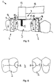
- the holder 6 has two approximately U-shaped Holding parts 9, each in the use position of the two adjacent teeth adjacent to the tooth gap 4 Reach over 2 in a fork shape (Fig. 5).
- Fig. 5 is one of the two U-legs of the holding part 9 on the inner and the other on the outer side surface of the neighboring tooth 2 assigned to it.
- the transition areas between the U-crossbar and the U-legs of the holding part 9 are rounded.
- the clear width between the U-legs of the holding part 9 takes starting from the free ends the U-leg towards the U-crosspiece preferably from continuously.
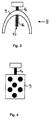
- the holding parts 9 are fastened to the adjacent teeth 2 by means of a solidifying potting compound. Before attaching the holding parts 9 on the neighboring teeth 2, this potting compound in pasty, mushy or viscous state on the inside Holding parts 9 applied. Then with the potting compound lined holding parts 9 attached to the neighboring teeth 2, wherein the sealing compound comes into contact with the neighboring teeth 2 and the spaces between the holding parts 9 and the neighboring teeth 2 fills out. The potting compound then solidifies in the mouth of the patient, so that the bracket is then firmly attached to the Neighbor teeth 2 is connected. The casting compound still shows a certain elasticity, so that the bracket 6 after the Editing the neighboring teeth in a simple way from the patient's teeth can be deducted. So that the casting compound when pulling off Bracket 6 adheres better to the holding parts 9, point the holding parts 9 holes in which the potting compound at Introduce into the holding parts 9 penetrates (Fig.4).
- the positioning device has 7 a sliding guide with a relative to the bracket 6 sliding carriage part 10.
- the carriage part 10 is mounted on parallel guide rails 11, the ends of each with one of the two in the use position holding parts 9 arranged on both sides of the tooth gap 4 are connected are.
- the guide strips 11 are in the use position in one Level arranged approximately parallel to the plane of the occlusal surfaces the neighboring teeth 2 run or are identical to them (FIG. 5).
- the slide part 10 is arranged between the holding parts 9 and for introducing the recesses 8 into the neighboring teeth 2 parallel to the guide strips 11 on the holding parts 9 and movable away from these.
- the holding parts 9 outside of the depressions to be introduced into the neighboring teeth 2 8 are arranged so that the machining tool 5 for removal of the tooth material moved into the receiving recesses 8 can be.
- the processing tool 5 is known per se Tool head 12 of a dental processing device arranged.
- the processing device has one in the drawing only partially shown handle part 13, in which one with the Machining tool 5 in electrical drive connection Drive motor is arranged.
- On the tool head 12 opposite end is the handle part 13 with a power supply line and optionally a water supply line to Supply of cooling water to the processing tool 5 connected.
- the tool head 12 is designed as an angle head and with it End area angled from the handle part 13 by about 90 °.
- the tool head 12 is detachable with the slide part 10 of the sliding guide is connectable.
- slide part 10 has an on the outer contour of the tool head 12 adapted receptacle 12a formed as a recess, into which the tool head 12 with its machining tool 5 facing end area can be used in a form-fitting manner. In doing so the receptacle 12a and the tool head 12 inserted therein Press fit, by means of which the tool head 12 in the receptacle 12a can be clamped.
- the tool head 12 and the slide part 10 or the receptacle 12a Plug-in coupling, the coupling parts of which can be detachably connected to one another are.
- the existing dental practices relatively expensive tool heads 12 with the positioning device 7 combined and thus continue to be used.
- the device 1 can also have its own, of existing ones Facilities independent drive for the machining tool 5, which preferably a directly on the slide part 10th arranged micro drive is.
- the machining tool 5 arranged on the tool head 12 is around a transverse to the direction of extension of the handle part 13 Rotation axis 14 driven by rotation. This is dashed in Fig.2 marked.
- the one inserted in the receptacle 12a of the slide part 10 Tool head 12 is relative to the holding parts about the axis of rotation 14 of the processing tool 5 pivotable with the holding parts 9 connected.
- the laterally on both sides of the slide part 10 arranged guide strips 11 engage in a common, an annular groove 15 arranged on the outer circumference of the slide part 10, such that the slide part 10 and the tool head 12 held therein on the one hand slidable along the guide strips 11 and on the other hand also about the axis of rotation relative to the Guide rails 11 is pivotable.
- the handle part 13 can thereby in a convenient position in the patient's oral cavity be pivoted.
- the swivel position of the handle part 13 if necessary, even during the movement of the on the slide part 10 guided tool head 12 can be changed to a good one To achieve accessibility to the respective processing point.
- each a spacer 16 with a transverse to the plane of the occlusal surface the neighboring teeth 2 adjustable support 17 for the Neighboring teeth 2 is arranged.
- the support point 17 is on the free end of an adjusting screw arranged the U-cross leg of the holding part 9 approximately in the direction of extension thereof U-legs penetrated.
- the adjusting screws each point to their the end 17 facing away from a screw head, the one Point of attack for a turning tool or by hand can be adjustable, in particular by means of an outer circumference of the screw head provided knurling.
- adjustment screws can be the height and / or incline of the guide rails 11 spanned level relative to the level of the occlusal surfaces teeth are adjusted. This makes it possible in particular to adapt the holder 6 to teeth of different heights, for example if one of the two holders 6 on a molar and the other is to be attached to a canine tooth.
- the machining tool 5 by means of the positioning device 7 can be shifted by a precisely defined distance
- 10 stops 18 on the brackets on both sides of the slide part 9 is provided, against which the slide part 10 can be positioned.
- This distance is adapted to the length of the dental bridge 4, which is the clear distance between the facing side surfaces the receiving recesses 8 of the two on both sides of the tooth gap 3 arranged adjacent teeth 2 of the dental bridge 4 including the Anchoring projections 19 corresponds. It is therefore independent of the respective geometrical dimensions of the tooth space 3 and Neighboring teeth 2 each ensure that the dental bridge 4 is accurate in the space formed between the receiving recesses 8 can be used.
- the holding parts 9 the device 1 attached to the adjacent teeth 2 of the tooth space 3.
- the tool head 12 with the machining tool 5 inserted into the receptacle 12a of the slide part 10 and positively connected to this.
- the editing tool rotates about the axis 14 and for introducing the receiving recesses 8 moved towards the neighboring teeth 2 until the Slide part 10 abuts the stop 18. If both shots 8 are completed, the device 1 from the dentition of the Patient removed.
- the prefabricated dental bridge 4 in the tooth gap 3 is inserted, the anchoring projections 19 engage in the recesses 8.
- the anchoring projections 19 and the receiving recesses 8 may be in the between the anchoring projections 19 and the receiving recesses 8 remaining gap a cement, adhesive or the like Fasteners and / or sealants introduced. After that Sealant is hardened or has solidified, the still visible surfaces of the anchoring protrusions and / or the adjacent areas of the neighboring teeth 2, if necessary be ground to the shape of the anchoring projections 19 adapt those of the neighboring teeth 2 and in particular a stepless, smooth transition between the adjacent teeth 2 and the anchoring projections 19 to achieve. If necessary, the Occlusal surface of the bridge part 20 is ground to the occlusion to improve.
- the device 1 for processing the adjacent teeth 2 of the tooth gap 3 is part of a kit for creating a dental bridge.
- the Kit has several pre-assembled dental bridges 4, the each a bridge part 20 with at least one artificial tooth the missing tooth (s) of the tooth gap 3 replaced.
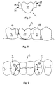
- an anchoring projection 19 on each side of the bridge part 20 provided with predetermined dimensions. 8 and 9 is recognizable that the dimensions of the anchoring projections 19 to those of the recesses 8 fit so that the in Tooth gap 3 used dental bridge 4 with their anchoring projections 19 connects directly to the neighboring teeth 2 or only is spaced from it by a small gap.
- Glue can be introduced in the gap.
- the dental bridge 4 is then after Firmly solidify the adhesive or cement the neighboring teeth 2 connected. 7 and 9 it can be seen that the anchoring projections arranged on both sides of the bridge part 20 19 the same, by the dimensions of the machining tool 5 given dimensions.
- the processing tool 5 has the shape of a truncated cone, starting from the tool head 12 to the free end of the Machining tool 5 tapers.
- the bridge part 20 facing lateral end faces 21 of the anchoring projections 19 are each on the outer surface of a shape of Machining tool 5 corresponding truncated cone arranged, starting from the occlusal surface of the bridge part 20 to the this opposite back of the bridge part 20 tapers.
- the Angle that the conical surface on a diameter plane of the Cone with a straight line parallel to the axis of the cone includes, is preferably between 0 and 6 °.
- the lateral end faces 21st the anchoring projections 19 of the dental bridge 4 have a surface roughness have and in particular can be sandblasted, so that a silanization layer applied to it adheres better. It is advisable for the dentist to do this shortly before insertion the dental bridge 4 on the lateral end faces 21 of the Anchoring projections 19 applied.
- the device 1 for processing the neighboring teeth 2 of a tooth gap 3 for the insertion of at least one missing tooth Dental bridge 4 has a machining tool 5 for removing Dental material, in particular a grinding tool.
- the Device 1 has a holder 6 for attachment to the dentition Patients who have an adjustable positioning device 7 for guided positioning of the machining tool 5 carries.
- the Processing tool 5 is for introducing recesses 8 into the sides of the neighboring teeth 2 facing the tooth gap 3 by means of the positioning device 7 towards and adjacent teeth 2 movable away from these.
Landscapes
- Health & Medical Sciences (AREA)
- Oral & Maxillofacial Surgery (AREA)
- Dentistry (AREA)
- Epidemiology (AREA)
- Life Sciences & Earth Sciences (AREA)
- Animal Behavior & Ethology (AREA)
- General Health & Medical Sciences (AREA)
- Public Health (AREA)
- Veterinary Medicine (AREA)
- Dental Tools And Instruments Or Auxiliary Dental Instruments (AREA)
- Dental Prosthetics (AREA)
Applications Claiming Priority (2)
| Application Number | Priority Date | Filing Date | Title |
|---|---|---|---|
| DE19948393A DE19948393C1 (de) | 1999-10-06 | 1999-10-06 | Vorrichtung zum Bearbeiten der Nachbarzähne einer Zahnlücke für das Einsetzen einer Zahnbrücke |
| DE19948393 | 1999-10-06 |
Publications (3)
| Publication Number | Publication Date |
|---|---|
| EP1090603A2 true EP1090603A2 (fr) | 2001-04-11 |
| EP1090603A3 EP1090603A3 (fr) | 2001-08-16 |
| EP1090603B1 EP1090603B1 (fr) | 2005-10-19 |
Family
ID=7924861
Family Applications (1)
| Application Number | Title | Priority Date | Filing Date |
|---|---|---|---|
| EP00119240A Expired - Lifetime EP1090603B1 (fr) | 1999-10-06 | 2000-09-06 | Ensemble pour réaliser un bridge dentaire |
Country Status (5)
| Country | Link |
|---|---|
| US (2) | US6537067B1 (fr) |
| EP (1) | EP1090603B1 (fr) |
| AT (1) | ATE306862T1 (fr) |
| DE (2) | DE19948393C1 (fr) |
| ES (1) | ES2250058T3 (fr) |
Families Citing this family (31)
| Publication number | Priority date | Publication date | Assignee | Title |
|---|---|---|---|---|
| US6626667B2 (en) * | 2002-01-16 | 2003-09-30 | Harold I. Sussman | Implant guide arrangement |
| WO2005058179A2 (fr) * | 2003-12-15 | 2005-06-30 | Delmonico Frank E | Systeme ajustable pour composites dentaires colles |
| US8177557B2 (en) * | 2003-12-15 | 2012-05-15 | Delmonico Frank E | Dental device, such as bridge or insert |
| US20080318186A1 (en) * | 2003-12-15 | 2008-12-25 | Delmonico Frank E | Dental device, such as a bridge or insert |
| US7874838B2 (en) * | 2005-02-28 | 2011-01-25 | Innovative Implant Technology, Llc | Instrument and process for the minimum distance verification between teeth for the placement of one or two bone integrated dental implants |
| ES2401019T3 (es) * | 2006-03-30 | 2013-04-16 | Friadent Gmbh | Sistema para la inserción de implantes |
| US20070298373A1 (en) * | 2006-06-22 | 2007-12-27 | W&H Dentalwerk Burmoos Gmbh | Implantological spacing device and implantological guide instrument for an implantological spacing device |
| US7905726B2 (en) * | 2006-10-10 | 2011-03-15 | Stumpel Lambert J | Surgical guide for dental implant and methods therefor |
| US20080220390A1 (en) * | 2007-03-07 | 2008-09-11 | Michael Klein | Dental tool guide assembly |
| JP5467726B2 (ja) * | 2007-09-12 | 2014-04-09 | イマグノーシス株式会社 | インプラント植立用穿孔器具、ハンドピース、ハンドピース用アダプタおよびサージカルガイド |
| FR2925289B1 (fr) * | 2007-12-20 | 2011-01-21 | Anthogyr Sa | Dispositif de centrage et de guidage d'un foret de piece a main dentaire |
| US8585402B2 (en) * | 2008-08-29 | 2013-11-19 | Zimmer Dental, Inc. | Dental drill guide system |
| US20100192375A1 (en) | 2009-02-02 | 2010-08-05 | Remedent Nv | Method for producing a dentist tool |
| US8640338B2 (en) | 2009-02-02 | 2014-02-04 | Viax Dental Technologies, LLC | Method of preparation for restoring tooth structure |
| KR101750846B1 (ko) * | 2009-02-02 | 2017-06-26 | 비악스 덴탈 테크놀로지스, 엘엘씨 | 치과 공구 제조 방법 |
| WO2011087794A1 (fr) * | 2009-12-22 | 2011-07-21 | Stumpel Lambert J | Guide chirurgical et procédé associé |
| CN103561675A (zh) | 2010-11-17 | 2014-02-05 | 可欧迪股份有限公司 | 牙齿修整导引装置以及针对口腔赝复的修整牙齿的方法 |
| KR20120053455A (ko) * | 2010-11-17 | 2012-05-25 | 안경숙 | 치아삭제 유도장치 |
| EP2739240B1 (fr) * | 2011-05-26 | 2020-07-15 | Viax Dental Technologies, Llc | Outil dentaire et dispositifs de guidage |
| ITFI20110130A1 (it) * | 2011-07-01 | 2013-01-02 | Leone Spa | Sistema di guida chirurgica per implantologia dentale e procedimento per la realizzazione di guide chirurgiche per implantologia dentale. |
| ES2670670T3 (es) | 2011-12-29 | 2018-05-31 | Swissmeda Ag | Plantilla quirúrgica para realizar implantología dental |
| EP2906141B1 (fr) * | 2012-10-10 | 2019-12-11 | James Harrison | Support de positionnement d'une prothèse dentaire finale, système incorporant le support |
| US9173723B2 (en) * | 2012-10-10 | 2015-11-03 | James Harrison | Method of installing a final dental prosthesis |
| US9408678B2 (en) | 2012-10-10 | 2016-08-09 | James Harrison | Cradle for positioning a final dental prosthesis and a system incorporating the cradle |
| WO2015137537A1 (fr) * | 2014-03-14 | 2015-09-17 | 안경숙 | Pièce à main dotée d'un guide de fraise |
| US9675425B2 (en) | 2015-03-02 | 2017-06-13 | Benjamin D. Oppenheimer | Apparatus for aligning a dental drill |
| US11007035B2 (en) * | 2017-03-16 | 2021-05-18 | Viax Dental Technologies Llc | System for preparing teeth for the placement of veneers |
| KR102112828B1 (ko) * | 2018-03-23 | 2020-05-19 | 김종민 | 임플란트용 드릴 인디케이터 |
| SG11202107144TA (en) | 2019-01-04 | 2021-07-29 | Viax Dental Tech Llc | Tooth preparation system with lateral prongs for limiting three-dimensional movement |
| CN112274272A (zh) * | 2019-07-23 | 2021-01-29 | 巧艺国际有限公司 | 植牙导引工具组及其植牙导引套 |
| KR102112829B1 (ko) * | 2020-03-05 | 2020-05-19 | 김종민 | 임플란트용 드릴 인디케이터 |
Citations (1)
| Publication number | Priority date | Publication date | Assignee | Title |
|---|---|---|---|---|
| DE684665C (de) | 1937-07-05 | 1939-12-02 | Dr E B Weigele | Vorrichtung zum parallelen Fuehren von Werkzeugen bei zahntechnischen Arbeiten mit einer nach allen Seiten drehbaren, laengs verschiebbaren und in der eingestellten Arbeitslage feststellbaren Fuehrungshuelse fuer das Werkzeug |
Family Cites Families (8)
| Publication number | Priority date | Publication date | Assignee | Title |
|---|---|---|---|---|
| US1407840A (en) * | 1921-03-22 | 1922-02-28 | Henry L Cruttenden | Dental parallel-cavity former |
| US2634501A (en) * | 1950-12-02 | 1953-04-14 | Linet Leo | Dental drill and gauge device |
| US3011259A (en) * | 1959-05-07 | 1961-12-05 | Baum Lloyd | Guide fixture for dental tools |
| CH611792A5 (fr) * | 1975-02-12 | 1979-06-29 | Werner Lutz Koch | |
| US4457714A (en) * | 1982-03-18 | 1984-07-03 | Klein Warren Z | Dental bridge and method of dental bridge fabrication |
| US4689013A (en) * | 1984-12-17 | 1987-08-25 | Lustig Leopold P | Modular system for restorative dentistry |
| US5171147A (en) * | 1990-04-30 | 1992-12-15 | Burgess Richard J | Dental bridge |
| US5934907A (en) * | 1997-06-23 | 1999-08-10 | Oro-Health International, Inc. | Dental prosthesis with multi-section infrastructure and method for replacement of teeth |
-
1999
- 1999-10-06 DE DE19948393A patent/DE19948393C1/de not_active Expired - Fee Related
-
2000
- 2000-09-06 ES ES00119240T patent/ES2250058T3/es not_active Expired - Lifetime
- 2000-09-06 EP EP00119240A patent/EP1090603B1/fr not_active Expired - Lifetime
- 2000-09-06 AT AT00119240T patent/ATE306862T1/de active
- 2000-09-06 DE DE50011362T patent/DE50011362D1/de not_active Expired - Lifetime
- 2000-10-05 US US09/680,084 patent/US6537067B1/en not_active Expired - Fee Related
-
2002
- 2002-11-06 US US10/288,913 patent/US6881059B2/en not_active Expired - Lifetime
Patent Citations (1)
| Publication number | Priority date | Publication date | Assignee | Title |
|---|---|---|---|---|
| DE684665C (de) | 1937-07-05 | 1939-12-02 | Dr E B Weigele | Vorrichtung zum parallelen Fuehren von Werkzeugen bei zahntechnischen Arbeiten mit einer nach allen Seiten drehbaren, laengs verschiebbaren und in der eingestellten Arbeitslage feststellbaren Fuehrungshuelse fuer das Werkzeug |
Also Published As
| Publication number | Publication date |
|---|---|
| DE19948393C1 (de) | 2001-03-22 |
| US6537067B1 (en) | 2003-03-25 |
| US20030064346A1 (en) | 2003-04-03 |
| US6881059B2 (en) | 2005-04-19 |
| EP1090603A3 (fr) | 2001-08-16 |
| ATE306862T1 (de) | 2005-11-15 |
| DE50011362D1 (de) | 2006-03-02 |
| EP1090603B1 (fr) | 2005-10-19 |
| ES2250058T3 (es) | 2006-04-16 |
Similar Documents
| Publication | Publication Date | Title |
|---|---|---|
| EP1090603B1 (fr) | Ensemble pour réaliser un bridge dentaire | |
| EP0291821B1 (fr) | Socle pour supporter le modèle en plâtre d'une denture | |
| EP0740534B1 (fr) | incrustation et outil d'elimination d'une lesion sur une dent | |
| EP1444963A1 (fr) | Pièce de raccord pour un implant dentaire, appareil de positionnement, et méthode de préparation une base pour une pièce de support | |
| DE3436094A1 (de) | Verfahren und vorrichtung zur herstellung des auf einer basisplatte festgelegten modells eines zahnkranzes | |
| DE102007029115B4 (de) | Fixierungsplatte und Verfahren zu ihrer Verwendung | |
| DE3534751C2 (fr) | ||
| DE69923685T2 (de) | Zahnmedizinische implantats-komponente | |
| CH676789A5 (fr) | ||
| DE69318697T2 (de) | Inlay, inlayhalter sowie zahnwiederherstellungsset | |
| DE19959383C1 (de) | Vorrichtung zur Präparation mindestens eines Zahnes zur Aufnahme einer Krone, Brücke o. dgl. | |
| EP1341471B1 (fr) | Dispositif de maintien pour modele de prothese dentaire ou de structure de base | |
| EP0008093A1 (fr) | Dispositif pour fabriquer des couronnes, bridges et autres prothèses dentaires | |
| EP1618853A1 (fr) | Pièce de compensation et procédé de mesure de restaurations dentaires | |
| EP0796063A1 (fr) | Procede de fabrication "sur mesure" d'articles prothetiques dentaires et procede de soins dentaires au moyen desdits articles | |
| DE69012553T2 (de) | Einheit zur befestigung von elementen auf einer basis. | |
| DE29917682U1 (de) | Vorrichtung zum Bearbeiten der Nachbarzähne einer Zahnlücke für das Einsetzen einer Zahnbrücke | |
| DE10241857A1 (de) | Verfahren und Vorrichtung zur Anfertigung einer Muffel für die Herstellung von Zahnersatz-Objekten | |
| DE3444165C2 (de) | Geschiebe | |
| DE4104299C2 (de) | Zahntechnischer Artikulator und Verfahren zur Herstellung von zahntechnischen Prothesen und Korrektureinrichtungen unter Verwendung des Artikulators | |
| DE102004034800B4 (de) | Aufbaukörper für Zahnkronenaufbausystem | |
| DE102013207048A1 (de) | Verfahren zur Herstellung eines Präzisionsgebissmodells für die Herstellung/Anpassung eines Zahnersatzes | |
| DE19529361A1 (de) | Verfahren zur Ausbildung einer Abphasung an der äußeren Kante der Kavität eines kariös gewordenen Zahnes sowie Vorrichtung zur Durchführung des Verfahrens | |
| DE19843385C1 (de) | Vorrichtung zur Präparation eines Zahns zur Aufnahme einer Krone, Brücke o. dgl. | |
| DE1766012C3 (de) | Bohrlehre für zahnärztliche Zwecke und Verfahren zum Herstellen derselben |
Legal Events
| Date | Code | Title | Description |
|---|---|---|---|
| PUAI | Public reference made under article 153(3) epc to a published international application that has entered the european phase |
Free format text: ORIGINAL CODE: 0009012 |
|
| AK | Designated contracting states |
Kind code of ref document: A2 Designated state(s): AT BE CH CY DE DK ES FI FR GB GR IE IT LI LU MC NL PT SE |
|
| AX | Request for extension of the european patent |
Free format text: AL;LT;LV;MK;RO;SI |
|
| PUAL | Search report despatched |
Free format text: ORIGINAL CODE: 0009013 |
|
| AK | Designated contracting states |
Kind code of ref document: A3 Designated state(s): AT BE CH CY DE DK ES FI FR GB GR IE IT LI LU MC NL PT SE |
|
| AX | Request for extension of the european patent |
Free format text: AL;LT;LV;MK;RO;SI |
|
| RIC1 | Information provided on ipc code assigned before grant |
Free format text: 7A 61C 1/08 A, 7A 61C 13/003 B |
|
| 17P | Request for examination filed |
Effective date: 20010727 |
|
| AKX | Designation fees paid |
Free format text: AT BE CH CY DE DK ES FI FR GB GR IE IT LI LU MC NL PT SE |
|
| 17Q | First examination report despatched |
Effective date: 20031126 |
|
| GRAP | Despatch of communication of intention to grant a patent |
Free format text: ORIGINAL CODE: EPIDOSNIGR1 |
|
| RTI1 | Title (correction) |
Free format text: KIT FOR MAKING A DENTAL BRIDGE |
|
| GRAS | Grant fee paid |
Free format text: ORIGINAL CODE: EPIDOSNIGR3 |
|
| GRAA | (expected) grant |
Free format text: ORIGINAL CODE: 0009210 |
|
| AK | Designated contracting states |
Kind code of ref document: B1 Designated state(s): AT BE CH CY DE DK ES FI FR GB GR IE IT LI LU MC NL PT SE |
|
| PG25 | Lapsed in a contracting state [announced via postgrant information from national office to epo] |
Ref country code: IE Free format text: LAPSE BECAUSE OF FAILURE TO SUBMIT A TRANSLATION OF THE DESCRIPTION OR TO PAY THE FEE WITHIN THE PRESCRIBED TIME-LIMIT Effective date: 20051019 Ref country code: FI Free format text: LAPSE BECAUSE OF FAILURE TO SUBMIT A TRANSLATION OF THE DESCRIPTION OR TO PAY THE FEE WITHIN THE PRESCRIBED TIME-LIMIT Effective date: 20051019 |
|
| REG | Reference to a national code |
Ref country code: GB Ref legal event code: FG4D Free format text: NOT ENGLISH |
|
| REG | Reference to a national code |
Ref country code: CH Ref legal event code: EP |
|
| REG | Reference to a national code |
Ref country code: CH Ref legal event code: NV Representative=s name: HANS RUDOLF GACHNANG PATENTANWALT |
|
| REG | Reference to a national code |
Ref country code: IE Ref legal event code: FG4D Free format text: LANGUAGE OF EP DOCUMENT: GERMAN |
|
| PG25 | Lapsed in a contracting state [announced via postgrant information from national office to epo] |
Ref country code: GR Free format text: LAPSE BECAUSE OF FAILURE TO SUBMIT A TRANSLATION OF THE DESCRIPTION OR TO PAY THE FEE WITHIN THE PRESCRIBED TIME-LIMIT Effective date: 20060119 Ref country code: DK Free format text: LAPSE BECAUSE OF FAILURE TO SUBMIT A TRANSLATION OF THE DESCRIPTION OR TO PAY THE FEE WITHIN THE PRESCRIBED TIME-LIMIT Effective date: 20060119 Ref country code: SE Free format text: LAPSE BECAUSE OF FAILURE TO SUBMIT A TRANSLATION OF THE DESCRIPTION OR TO PAY THE FEE WITHIN THE PRESCRIBED TIME-LIMIT Effective date: 20060119 |
|
| GBT | Gb: translation of ep patent filed (gb section 77(6)(a)/1977) |
Effective date: 20060202 |
|
| REF | Corresponds to: |
Ref document number: 50011362 Country of ref document: DE Date of ref document: 20060302 Kind code of ref document: P |
|
| PG25 | Lapsed in a contracting state [announced via postgrant information from national office to epo] |
Ref country code: PT Free format text: LAPSE BECAUSE OF FAILURE TO SUBMIT A TRANSLATION OF THE DESCRIPTION OR TO PAY THE FEE WITHIN THE PRESCRIBED TIME-LIMIT Effective date: 20060320 |
|
| REG | Reference to a national code |
Ref country code: ES Ref legal event code: FG2A Ref document number: 2250058 Country of ref document: ES Kind code of ref document: T3 |
|
| REG | Reference to a national code |
Ref country code: IE Ref legal event code: FD4D |
|
| ET | Fr: translation filed | ||
| PLBE | No opposition filed within time limit |
Free format text: ORIGINAL CODE: 0009261 |
|
| STAA | Information on the status of an ep patent application or granted ep patent |
Free format text: STATUS: NO OPPOSITION FILED WITHIN TIME LIMIT |
|
| 26N | No opposition filed |
Effective date: 20060720 |
|
| PG25 | Lapsed in a contracting state [announced via postgrant information from national office to epo] |
Ref country code: BE Free format text: LAPSE BECAUSE OF NON-PAYMENT OF DUE FEES Effective date: 20060930 Ref country code: MC Free format text: LAPSE BECAUSE OF NON-PAYMENT OF DUE FEES Effective date: 20060930 |
|
| BERE | Be: lapsed |
Owner name: WENNEMANN, ULRICH Effective date: 20060930 |
|
| PG25 | Lapsed in a contracting state [announced via postgrant information from national office to epo] |
Ref country code: LU Free format text: LAPSE BECAUSE OF NON-PAYMENT OF DUE FEES Effective date: 20060906 |
|
| PG25 | Lapsed in a contracting state [announced via postgrant information from national office to epo] |
Ref country code: CY Free format text: LAPSE BECAUSE OF FAILURE TO SUBMIT A TRANSLATION OF THE DESCRIPTION OR TO PAY THE FEE WITHIN THE PRESCRIBED TIME-LIMIT Effective date: 20051019 |
|
| PGFP | Annual fee paid to national office [announced via postgrant information from national office to epo] |
Ref country code: AT Payment date: 20100928 Year of fee payment: 11 |
|
| PGFP | Annual fee paid to national office [announced via postgrant information from national office to epo] |
Ref country code: ES Payment date: 20110707 Year of fee payment: 12 |
|
| PGFP | Annual fee paid to national office [announced via postgrant information from national office to epo] |
Ref country code: IT Payment date: 20110914 Year of fee payment: 12 Ref country code: NL Payment date: 20110922 Year of fee payment: 12 |
|
| PGFP | Annual fee paid to national office [announced via postgrant information from national office to epo] |
Ref country code: CH Payment date: 20110930 Year of fee payment: 12 |
|
| PGFP | Annual fee paid to national office [announced via postgrant information from national office to epo] |
Ref country code: GB Payment date: 20120823 Year of fee payment: 13 |
|
| REG | Reference to a national code |
Ref country code: AT Ref legal event code: MM01 Ref document number: 306862 Country of ref document: AT Kind code of ref document: T Effective date: 20110906 |
|
| PGFP | Annual fee paid to national office [announced via postgrant information from national office to epo] |
Ref country code: FR Payment date: 20120802 Year of fee payment: 13 |
|
| PG25 | Lapsed in a contracting state [announced via postgrant information from national office to epo] |
Ref country code: AT Free format text: LAPSE BECAUSE OF NON-PAYMENT OF DUE FEES Effective date: 20110906 |
|
| REG | Reference to a national code |
Ref country code: NL Ref legal event code: V1 Effective date: 20130401 |
|
| REG | Reference to a national code |
Ref country code: CH Ref legal event code: PL |
|
| PG25 | Lapsed in a contracting state [announced via postgrant information from national office to epo] |
Ref country code: CH Free format text: LAPSE BECAUSE OF NON-PAYMENT OF DUE FEES Effective date: 20120930 Ref country code: LI Free format text: LAPSE BECAUSE OF NON-PAYMENT OF DUE FEES Effective date: 20120930 |
|
| PG25 | Lapsed in a contracting state [announced via postgrant information from national office to epo] |
Ref country code: IT Free format text: LAPSE BECAUSE OF NON-PAYMENT OF DUE FEES Effective date: 20120906 Ref country code: NL Free format text: LAPSE BECAUSE OF NON-PAYMENT OF DUE FEES Effective date: 20130401 |
|
| REG | Reference to a national code |
Ref country code: ES Ref legal event code: FD2A Effective date: 20131022 |
|
| PGFP | Annual fee paid to national office [announced via postgrant information from national office to epo] |
Ref country code: DE Payment date: 20130917 Year of fee payment: 14 |
|
| GBPC | Gb: european patent ceased through non-payment of renewal fee |
Effective date: 20130906 |
|
| PG25 | Lapsed in a contracting state [announced via postgrant information from national office to epo] |
Ref country code: ES Free format text: LAPSE BECAUSE OF NON-PAYMENT OF DUE FEES Effective date: 20120907 |
|
| REG | Reference to a national code |
Ref country code: FR Ref legal event code: ST Effective date: 20140530 |
|
| PG25 | Lapsed in a contracting state [announced via postgrant information from national office to epo] |
Ref country code: GB Free format text: LAPSE BECAUSE OF NON-PAYMENT OF DUE FEES Effective date: 20130906 |
|
| PG25 | Lapsed in a contracting state [announced via postgrant information from national office to epo] |
Ref country code: FR Free format text: LAPSE BECAUSE OF NON-PAYMENT OF DUE FEES Effective date: 20130930 |
|
| REG | Reference to a national code |
Ref country code: DE Ref legal event code: R119 Ref document number: 50011362 Country of ref document: DE |
|
| REG | Reference to a national code |
Ref country code: DE Ref legal event code: R119 Ref document number: 50011362 Country of ref document: DE Effective date: 20150401 |
|
| PG25 | Lapsed in a contracting state [announced via postgrant information from national office to epo] |
Ref country code: DE Free format text: LAPSE BECAUSE OF NON-PAYMENT OF DUE FEES Effective date: 20150401 |