EP0180710A2 - Dispositif de transport des colis de détail ou des marchandises semblables - Google Patents
Dispositif de transport des colis de détail ou des marchandises semblables Download PDFInfo
- Publication number
- EP0180710A2 EP0180710A2 EP85107617A EP85107617A EP0180710A2 EP 0180710 A2 EP0180710 A2 EP 0180710A2 EP 85107617 A EP85107617 A EP 85107617A EP 85107617 A EP85107617 A EP 85107617A EP 0180710 A2 EP0180710 A2 EP 0180710A2
- Authority
- EP
- European Patent Office
- Prior art keywords
- rolling elements
- plate
- transport device
- segments
- balls
- Prior art date
- Legal status (The legal status is an assumption and is not a legal conclusion. Google has not performed a legal analysis and makes no representation as to the accuracy of the status listed.)
- Granted
Links
Images

Classifications
-
- B—PERFORMING OPERATIONS; TRANSPORTING
- B65—CONVEYING; PACKING; STORING; HANDLING THIN OR FILAMENTARY MATERIAL
- B65G—TRANSPORT OR STORAGE DEVICES, e.g. CONVEYORS FOR LOADING OR TIPPING, SHOP CONVEYOR SYSTEMS OR PNEUMATIC TUBE CONVEYORS
- B65G13/00—Roller-ways
- B65G13/02—Roller-ways having driven rollers
- B65G13/06—Roller driving means
- B65G13/071—Roller driving means with frictional engagement
-
- B—PERFORMING OPERATIONS; TRANSPORTING
- B65—CONVEYING; PACKING; STORING; HANDLING THIN OR FILAMENTARY MATERIAL
- B65G—TRANSPORT OR STORAGE DEVICES, e.g. CONVEYORS FOR LOADING OR TIPPING, SHOP CONVEYOR SYSTEMS OR PNEUMATIC TUBE CONVEYORS
- B65G39/00—Rollers, e.g. drive rollers, or arrangements thereof incorporated in roller-ways or other types of mechanical conveyors
- B65G39/02—Adaptations of individual rollers and supports therefor
- B65G39/025—Adaptations of individual rollers and supports therefor having spherical roller elements
Definitions
- the invention relates to a transport device for piece goods or the like of the type referred to in the preamble of claim 1.
- Such a transport device is known from DE -AS 22 61 936; there, however, it is designed as a conveyor route switch for transferring piece goods from a first conveyor to at least a second conveyor which runs in a different direction than the first conveyor.
- the individual drive devices consist of drive actuators rotatable parallel to the conveying surface, on each of which one of the rolling elements is supported eccentrically, all of the drive actuators being rotatably mounted on a common bearing plate, while the plate with the passage openings is arranged in a stationary manner as a holder for the rolling elements.
- the known conveyor switch is too complex for linear conveying devices. It is therefore only used as a short transfer deck.
- roller conveyors which can be moved in height below a stationary top plate with through openings for the individual rollers are arranged.
- the top plate In the lowered state of the roller conveyor, the top plate can be driven on by vehicles, such as forklifts, hand pallet trucks or the like, without the individual rollers of the roller conveyor being overloaded by selective loading by the vehicle wheels.
- the drive of the individual rollers seated on axles is cumbersome and is additionally complicated by the lifting device.
- the surface cutouts in the top plate which are open when the roller conveyor is lowered are a danger point, and dirt and larger particles can get into these openings when the rollers are lowered and impair the function of the lifting device and the rollers themselves.
- drawing carpets Also known as linear transport systems of the type in question are so-called drawing carpets, which are driven by deflection drums and are pulled over a sliding surface. Very high friction forces occur between the carpet and the sliding surface, which require high drive power and are responsible for rapid wear of the carpet material. In addition, the carpet material cannot withstand partial loads, particularly due to sharp edges on the piece goods.
- the invention is therefore based on the object of designing a transport device of the generic type as a linear conveying device which has simple drive devices for the rolling elements which are insensitive to heavy loads and consequently can also be run over by vehicles without lowering the rolling elements.
- the particular advantage of a transport device according to the invention is that the rolling elements supported on the shafts absorb high vertical forces and can dissipate them via the drive shafts on the underside. In the overrun mode, only the rolling elements are stopped and there are no disruptive cutouts in the top of the plate into which dirt and other disruptive particles could penetrate. The rolling elements can be blocked at a standstill by frictional engagement with the drive shafts. so that no slipping effects occur as with ball conveyor tracks with non-driven balls.
- balls are used as rolling elements in the transport device according to the invention, which have particularly favorable driving characteristics.
- the shafts carrying the rolling elements can be supported on particularly stiffened cross members, and the shafts can extend across the entire length of a row of balls transversely to the transport direction with appropriate intermediate support.
- the shafts are expediently driven via external drive wheels, such as chain pulleys or toothed belt wheels, on the one hand to ensure synchronous drive of the rolling elements and to enable the connection to a central drive motor.
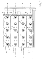
- the drawing shows plate-shaped in detail. Segments 1, which are arranged transversely to the conveying direction of the transport device. On the underside, the segments 1 are firmly connected to beams 2 with a U-shaped cross section in order to achieve sufficient bending rigidity for the segments 1. The upper sides 6 of the segments 1 are flush with one another in order to obtain a closed upper side of the transport device which can be driven over by vehicles. In contrast to the drawing, a continuous plate can also be used instead of the individual, stiffened plate segments 1.
- Holes 3 are machined vertically from top to bottom in the segments 1 and the supports 2, each of which complements a straight line extending transversely to the transport direction.
- a guide sleeve 4 is used, which is flush with the top 6 of the segment 1.
- the guide sleeves 4 each receive a ball 5, which projects with its top side above the top 6 of the plate segments 1.
- the balls 5 also form rows 7 arranged transversely to the transport direction, which in the exemplary embodiment shown are parallel to one another, but in principle can also be arranged at an angle to one another.
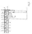
- all balls 5 of a row of balls 7 are supported on a cylindrical shaft 8, which is arranged below the segments 1 between the U-flanges of the cross members 2.
- the axis of the shaft 8 is parallel to the connecting line of the center points of the balls 5 of a row 7, which is why the center points of the balls 5 lie in the vertical plane passing through the axis of the associated shaft 8 due to the straight line alignment of the rows of balls 7.
- the sleeves 3 are each aligned with their axes at right angles to the axis of the shaft 8 and hold the individual balls 5 even when the shaft 8 rotates in the central orientation thereof.
- Each of the shafts 8 is divided into individual, suitably equally long sections 9, between each of which there is a bearing element 10 which is fixedly connected to the associated cross member 2.
- On each of the shaft portions 9 are two balls 5 are superimposed, with the distance of the individual balls 5 to the respective adjacent bearing member 1 0 equal to half the distance between the adjacent balls 5 is another. Since the balls 5 all on occurring vertical forces can only be transmitted to the shaft 8, an optimal load distribution on the shaft 8 can be achieved.
- drive wheels 11 such as chain wheels or toothed belt pulleys
- the shaft ends extended beyond the respective end bearing elements 1 0 are placed on the shaft ends extended beyond the respective end bearing elements 1 0 , and all or at least several of the shafts 8 are connected to one another without slip by corresponding chain or toothed belt drives.
- One of these shafts 8 is connected via a further intermediate drive 12 to a central drive motor 13 arranged below in the frame of the device.
Landscapes
- Engineering & Computer Science (AREA)
- Mechanical Engineering (AREA)
- Rollers For Roller Conveyors For Transfer (AREA)
- Paper (AREA)
- Forklifts And Lifting Vehicles (AREA)
- Container, Conveyance, Adherence, Positioning, Of Wafer (AREA)
- Bearings For Parts Moving Linearly (AREA)
- Control And Other Processes For Unpacking Of Materials (AREA)
- Catching Or Destruction (AREA)
Priority Applications (1)
| Application Number | Priority Date | Filing Date | Title |
|---|---|---|---|
| AT85107617T ATE48821T1 (de) | 1984-11-02 | 1985-06-20 | Transportvorrichtung fuer stueckgueter oder dergleichen. |
Applications Claiming Priority (2)
| Application Number | Priority Date | Filing Date | Title |
|---|---|---|---|
| DE3439966 | 1984-11-02 | ||
| DE3439966A DE3439966C2 (de) | 1984-11-02 | 1984-11-02 | Transportvorrichtung für Stückgüter oder dergleichen |
Publications (3)
| Publication Number | Publication Date |
|---|---|
| EP0180710A2 true EP0180710A2 (fr) | 1986-05-14 |
| EP0180710A3 EP0180710A3 (en) | 1986-12-30 |
| EP0180710B1 EP0180710B1 (fr) | 1989-12-20 |
Family
ID=6249254
Family Applications (1)
| Application Number | Title | Priority Date | Filing Date |
|---|---|---|---|
| EP85107617A Expired EP0180710B1 (fr) | 1984-11-02 | 1985-06-20 | Dispositif de transport des colis de détail ou des marchandises semblables |
Country Status (6)
| Country | Link |
|---|---|
| US (1) | US4681211A (fr) |
| EP (1) | EP0180710B1 (fr) |
| JP (1) | JPS61114910A (fr) |
| KR (1) | KR910004255B1 (fr) |
| AT (1) | ATE48821T1 (fr) |
| DE (2) | DE3439966C2 (fr) |
Cited By (7)
| Publication number | Priority date | Publication date | Assignee | Title |
|---|---|---|---|---|
| EP0294498A1 (fr) * | 1987-06-09 | 1988-12-14 | Carl Schenck Ag | Transporteur à rouleaux à friction avec boîtier |
| FR2616498A1 (fr) * | 1987-06-12 | 1988-12-16 | Leclere Philippe | Procede de calage, de freinage ou de transmission et dispositifs utilisant ce procede |
| WO1989007081A1 (fr) * | 1988-01-28 | 1989-08-10 | Fmc Corporation | Assemblage et plancher de billes roulantes |
| EP0276881B1 (fr) * | 1987-01-16 | 1992-03-25 | Fmc Corporation | Système de transport avec sphères entrainées et moyens de protection contre les sur charges |
| US5261526A (en) * | 1987-01-16 | 1993-11-16 | Fmc Corporation | Conveyor system with driven balls, protectable against overloading |
| EP0932566A4 (fr) * | 1996-06-25 | 1999-09-08 | ||
| DE102009026388A1 (de) | 2009-08-17 | 2011-02-24 | Krones Ag | Flächenantrieb, Verfahren und Vorrichtung zum Transport, zur Sortierung, Verschiebung und/oder Verteilung von Artikeln auf einer Auflage |
Families Citing this family (6)
| Publication number | Priority date | Publication date | Assignee | Title |
|---|---|---|---|---|
| DE3637003C1 (de) * | 1986-10-30 | 1988-02-04 | Loedige Foerdertechnik | Transportdeck fuer Stueckgueter oder dergleichen |
| US5238099A (en) * | 1992-08-04 | 1993-08-24 | Premark Feg Corporation | Conveying system |
| USD516767S1 (en) | 2003-09-26 | 2006-03-07 | Span Tech Llc | Rotatable article engaging assembly |
| US6874617B1 (en) * | 2003-09-26 | 2005-04-05 | Span Tech Llc | Modular link conveyor chain with rotatable article engaging assemblies |
| JP5902108B2 (ja) * | 2013-02-07 | 2016-04-13 | 株式会社Ihi検査計測 | X線検査用車両搬送装置 |
| CN106477230A (zh) * | 2015-09-02 | 2017-03-08 | 天津鑫宝龙电梯集团有限公司 | 一种传送桌 |
Family Cites Families (11)
| Publication number | Priority date | Publication date | Assignee | Title |
|---|---|---|---|---|
| DE1135368B (de) * | 1959-09-24 | 1962-08-23 | Fahrzeug Und Geraetewerk | Rollgang mit Geruesten |
| JPS4311960Y1 (fr) * | 1964-09-15 | 1968-05-23 | ||
| DE1289778B (de) * | 1964-12-12 | 1969-02-20 | Heinemann | Roellchenbahnweiche |
| GB1200725A (en) * | 1966-10-24 | 1970-07-29 | Sovex Ltd | Improvements relating to article-diverting apparatus |
| US3416642A (en) * | 1966-12-28 | 1968-12-17 | C F Butz Engineering Azusa | Pressureless accumulation conveyor |
| BE793824A (fr) * | 1972-01-11 | 1973-07-10 | Wagner Ab Fredr | Mecanisme d'aiguillage pour transporteurs |
| GB1366206A (en) * | 1972-07-07 | 1974-09-11 | Sovex Ltd | Diverting arrangements for example in conveying devices |
| DE2335874A1 (de) * | 1973-07-14 | 1975-01-30 | Stumpf Kg K | Angetriebene rollenbahnweiche |
| SU674955A1 (ru) * | 1978-01-20 | 1979-07-25 | Goldenberg Bentsion | Шарова опора конвейера |
| SU874678A2 (ru) * | 1980-01-25 | 1981-10-23 | Одесский филиал Всесоюзного научно-исследовательского и проектно-конструкторского института стекольного машиностроения | Секци рольганга |
| SU893739A2 (ru) * | 1980-03-06 | 1981-12-30 | Витебское Производственное Деревообрабатывающее Объединение "Витебскдрев" | Роликоопора рольганга |
-
1984
- 1984-11-02 DE DE3439966A patent/DE3439966C2/de not_active Expired
-
1985
- 1985-06-20 EP EP85107617A patent/EP0180710B1/fr not_active Expired
- 1985-06-20 AT AT85107617T patent/ATE48821T1/de not_active IP Right Cessation
- 1985-06-20 DE DE8585107617T patent/DE3574860D1/de not_active Expired - Lifetime
- 1985-09-06 KR KR1019850006505A patent/KR910004255B1/ko not_active Expired
- 1985-09-24 JP JP60208989A patent/JPS61114910A/ja active Granted
- 1985-10-25 US US06/791,361 patent/US4681211A/en not_active Expired - Lifetime
Cited By (10)
| Publication number | Priority date | Publication date | Assignee | Title |
|---|---|---|---|---|
| EP0276881B1 (fr) * | 1987-01-16 | 1992-03-25 | Fmc Corporation | Système de transport avec sphères entrainées et moyens de protection contre les sur charges |
| US5147032A (en) * | 1987-01-16 | 1992-09-15 | Fmc Corporation | Conveyor system with driven balls, protectable against overloading |
| US5261526A (en) * | 1987-01-16 | 1993-11-16 | Fmc Corporation | Conveyor system with driven balls, protectable against overloading |
| EP0294498A1 (fr) * | 1987-06-09 | 1988-12-14 | Carl Schenck Ag | Transporteur à rouleaux à friction avec boîtier |
| FR2616498A1 (fr) * | 1987-06-12 | 1988-12-16 | Leclere Philippe | Procede de calage, de freinage ou de transmission et dispositifs utilisant ce procede |
| WO1989007081A1 (fr) * | 1988-01-28 | 1989-08-10 | Fmc Corporation | Assemblage et plancher de billes roulantes |
| US5160017A (en) * | 1988-01-28 | 1992-11-03 | Fmc Corporation | Rolling ball assembly and deck |
| EP0932566A4 (fr) * | 1996-06-25 | 1999-09-08 | ||
| US6065665A (en) * | 1996-06-25 | 2000-05-23 | Fmc Corporation | Ball deck |
| DE102009026388A1 (de) | 2009-08-17 | 2011-02-24 | Krones Ag | Flächenantrieb, Verfahren und Vorrichtung zum Transport, zur Sortierung, Verschiebung und/oder Verteilung von Artikeln auf einer Auflage |
Also Published As
| Publication number | Publication date |
|---|---|
| EP0180710A3 (en) | 1986-12-30 |
| KR860003957A (ko) | 1986-06-16 |
| KR910004255B1 (ko) | 1991-06-25 |
| US4681211A (en) | 1987-07-21 |
| DE3439966A1 (de) | 1986-05-22 |
| DE3439966C2 (de) | 1986-09-18 |
| EP0180710B1 (fr) | 1989-12-20 |
| JPH0224724B2 (fr) | 1990-05-30 |
| ATE48821T1 (de) | 1990-01-15 |
| DE3574860D1 (de) | 1990-01-25 |
| JPS61114910A (ja) | 1986-06-02 |
Similar Documents
| Publication | Publication Date | Title |
|---|---|---|
| DE2431244C2 (de) | Werkstück-Förderer | |
| DE69203528T2 (de) | Fördervorrichtung für Artikel. | |
| DE2611556A1 (de) | Automatisches sortierfoerdersystem | |
| EP0545398A1 (fr) | Dispositif pour le transport d'objets | |
| EP0180710B1 (fr) | Dispositif de transport des colis de détail ou des marchandises semblables | |
| EP1042196B1 (fr) | Convoyeur et element de transport correspondant | |
| DE69103565T2 (de) | Rollenförderer. | |
| DE2328206A1 (de) | Antriebsschiene fuer einen foerderer | |
| EP0952102B1 (fr) | Dispositif de transfert d'articles, en particulier porte-charges pour pièces à travailler, pièces à travailler, conteneurs ou palettes | |
| EP3529180B1 (fr) | Système de transport | |
| EP0856480A1 (fr) | Moyen de transport guidé sur rails et système de transport avec un tel moyen de transport | |
| EP1115638B1 (fr) | Dispositif de distribution pour articles individuels | |
| DE10020909B4 (de) | Vorrichtung zur Förderung einer Vorratsrolle | |
| EP0321680B1 (fr) | Dispositif servant à enlever des articles | |
| EP0664262A1 (fr) | Elément de transport basculant pour transporteur d'articles (trieuse) | |
| DE2510347C2 (de) | Vorrichtung zum Überführen einer Last von einem Rollenförderer auf eine senkrecht dazu verlaufende zweite Fördereinrichtung | |
| DE2355143B2 (de) | Paletten-Umsetzvorrichtung | |
| EP0319549A1 (fr) | Systeme de transport. | |
| DE4111497A1 (de) | Stapelvorrichtung fuer paletten | |
| EP1090696B1 (fr) | Dispositif d'entrainement à chaines pour tréfilage en continu | |
| EP0161412A1 (fr) | Dispositif de transport pour convoyer des montages supports de pièces | |
| DE3235756A1 (de) | Stetigfoerderer, insbesondere tragkettenfoerderer | |
| DE3124898C2 (de) | Vorrichtung zum Überführen und Umlenken von Paletten | |
| DE10044048B4 (de) | Vorrichtung zum Überführen von Transportmitteln | |
| EP1266550B1 (fr) | Dispositif de transport de plaquettes de circuits imprimes |
Legal Events
| Date | Code | Title | Description |
|---|---|---|---|
| PUAI | Public reference made under article 153(3) epc to a published international application that has entered the european phase |
Free format text: ORIGINAL CODE: 0009012 |
|
| AK | Designated contracting states |
Kind code of ref document: A2 Designated state(s): AT BE CH DE FR GB IT LI LU NL SE |
|
| PUAL | Search report despatched |
Free format text: ORIGINAL CODE: 0009013 |
|
| AK | Designated contracting states |
Kind code of ref document: A3 Designated state(s): AT BE CH DE FR GB IT LI LU NL SE |
|
| 17P | Request for examination filed |
Effective date: 19870126 |
|
| 17Q | First examination report despatched |
Effective date: 19871103 |
|
| RAP1 | Party data changed (applicant data changed or rights of an application transferred) |
Owner name: LOEDIGE FOERDERTECHNIK GESELLSCHAFT MIT BESCHRAENK |
|
| RAP3 | Party data changed (applicant data changed or rights of an application transferred) |
Owner name: LOEDIGE FOERDERTECHNIK GESELLSCHAFT MIT BESCHRAENK |
|
| GRAA | (expected) grant |
Free format text: ORIGINAL CODE: 0009210 |
|
| AK | Designated contracting states |
Kind code of ref document: B1 Designated state(s): AT BE CH DE FR GB IT LI LU NL SE |
|
| REF | Corresponds to: |
Ref document number: 48821 Country of ref document: AT Date of ref document: 19900115 Kind code of ref document: T |
|
| REF | Corresponds to: |
Ref document number: 3574860 Country of ref document: DE Date of ref document: 19900125 |
|
| ET | Fr: translation filed | ||
| ITF | It: translation for a ep patent filed | ||
| GBT | Gb: translation of ep patent filed (gb section 77(6)(a)/1977) | ||
| PLBE | No opposition filed within time limit |
Free format text: ORIGINAL CODE: 0009261 |
|
| STAA | Information on the status of an ep patent application or granted ep patent |
Free format text: STATUS: NO OPPOSITION FILED WITHIN TIME LIMIT |
|
| 26N | No opposition filed | ||
| ITTA | It: last paid annual fee | ||
| EPTA | Lu: last paid annual fee | ||
| EAL | Se: european patent in force in sweden |
Ref document number: 85107617.4 |
|
| PGFP | Annual fee paid to national office [announced via postgrant information from national office to epo] |
Ref country code: SE Payment date: 19960529 Year of fee payment: 12 |
|
| PGFP | Annual fee paid to national office [announced via postgrant information from national office to epo] |
Ref country code: LU Payment date: 19960601 Year of fee payment: 12 |
|
| PGFP | Annual fee paid to national office [announced via postgrant information from national office to epo] |
Ref country code: AT Payment date: 19960611 Year of fee payment: 12 |
|
| PGFP | Annual fee paid to national office [announced via postgrant information from national office to epo] |
Ref country code: CH Payment date: 19960621 Year of fee payment: 12 |
|
| PGFP | Annual fee paid to national office [announced via postgrant information from national office to epo] |
Ref country code: BE Payment date: 19960701 Year of fee payment: 12 |
|
| PG25 | Lapsed in a contracting state [announced via postgrant information from national office to epo] |
Ref country code: LU Free format text: LAPSE BECAUSE OF NON-PAYMENT OF DUE FEES Effective date: 19970620 Ref country code: AT Effective date: 19970620 |
|
| PG25 | Lapsed in a contracting state [announced via postgrant information from national office to epo] |
Ref country code: SE Effective date: 19970621 |
|
| PG25 | Lapsed in a contracting state [announced via postgrant information from national office to epo] |
Ref country code: LI Free format text: LAPSE BECAUSE OF NON-PAYMENT OF DUE FEES Effective date: 19970630 Ref country code: CH Free format text: LAPSE BECAUSE OF NON-PAYMENT OF DUE FEES Effective date: 19970630 Ref country code: BE Effective date: 19970630 |
|
| BERE | Be: lapsed |
Owner name: LODIGE FORDERTECHNIK G.M.B.H. Effective date: 19970630 |
|
| REG | Reference to a national code |
Ref country code: CH Ref legal event code: PL |
|
| EUG | Se: european patent has lapsed |
Ref document number: 85107617.4 |
|
| PGFP | Annual fee paid to national office [announced via postgrant information from national office to epo] |
Ref country code: DE Payment date: 20010522 Year of fee payment: 17 |
|
| PGFP | Annual fee paid to national office [announced via postgrant information from national office to epo] |
Ref country code: GB Payment date: 20010612 Year of fee payment: 17 |
|
| PGFP | Annual fee paid to national office [announced via postgrant information from national office to epo] |
Ref country code: FR Payment date: 20010614 Year of fee payment: 17 |
|
| PGFP | Annual fee paid to national office [announced via postgrant information from national office to epo] |
Ref country code: NL Payment date: 20010630 Year of fee payment: 17 |
|
| REG | Reference to a national code |
Ref country code: GB Ref legal event code: IF02 |
|
| PG25 | Lapsed in a contracting state [announced via postgrant information from national office to epo] |
Ref country code: GB Free format text: LAPSE BECAUSE OF NON-PAYMENT OF DUE FEES Effective date: 20020620 |
|
| PG25 | Lapsed in a contracting state [announced via postgrant information from national office to epo] |
Ref country code: NL Free format text: LAPSE BECAUSE OF NON-PAYMENT OF DUE FEES Effective date: 20030101 Ref country code: DE Free format text: LAPSE BECAUSE OF NON-PAYMENT OF DUE FEES Effective date: 20030101 |
|
| GBPC | Gb: european patent ceased through non-payment of renewal fee |
Effective date: 20020620 |
|
| PG25 | Lapsed in a contracting state [announced via postgrant information from national office to epo] |
Ref country code: FR Free format text: LAPSE BECAUSE OF NON-PAYMENT OF DUE FEES Effective date: 20030228 |
|
| NLV4 | Nl: lapsed or anulled due to non-payment of the annual fee |
Effective date: 20030101 |
|
| REG | Reference to a national code |
Ref country code: FR Ref legal event code: ST |