EP1090782A2 - Dispositif d'attelage pour véhicules automobiles - Google Patents
Dispositif d'attelage pour véhicules automobiles Download PDFInfo
- Publication number
- EP1090782A2 EP1090782A2 EP00119819A EP00119819A EP1090782A2 EP 1090782 A2 EP1090782 A2 EP 1090782A2 EP 00119819 A EP00119819 A EP 00119819A EP 00119819 A EP00119819 A EP 00119819A EP 1090782 A2 EP1090782 A2 EP 1090782A2
- Authority
- EP
- European Patent Office
- Prior art keywords
- ball rod
- joint
- guide
- ball
- clutch housing
- Prior art date
- Legal status (The legal status is an assumption and is not a legal conclusion. Google has not performed a legal analysis and makes no representation as to the accuracy of the status listed.)
- Withdrawn
Links
Images
Classifications
-
- B—PERFORMING OPERATIONS; TRANSPORTING
- B60—VEHICLES IN GENERAL
- B60D—VEHICLE CONNECTIONS
- B60D1/00—Traction couplings; Hitches; Draw-gear; Towing devices
- B60D1/24—Traction couplings; Hitches; Draw-gear; Towing devices characterised by arrangements for particular functions
- B60D1/246—Traction couplings; Hitches; Draw-gear; Towing devices characterised by arrangements for particular functions for actuating the hitch by powered means
-
- B—PERFORMING OPERATIONS; TRANSPORTING
- B60—VEHICLES IN GENERAL
- B60D—VEHICLE CONNECTIONS
- B60D1/00—Traction couplings; Hitches; Draw-gear; Towing devices
- B60D1/01—Traction couplings or hitches characterised by their type
- B60D1/06—Ball-and-socket hitches
-
- B—PERFORMING OPERATIONS; TRANSPORTING
- B60—VEHICLES IN GENERAL
- B60D—VEHICLE CONNECTIONS
- B60D1/00—Traction couplings; Hitches; Draw-gear; Towing devices
- B60D1/48—Traction couplings; Hitches; Draw-gear; Towing devices characterised by the mounting
- B60D1/54—Traction couplings; Hitches; Draw-gear; Towing devices characterised by the mounting collapsible or retractable when not in use, e.g. hide-away hitches
Definitions
- the invention is based on a trailer coupling for Motor vehicles, especially passenger cars, according to the Genus of the main claim.
- a known trailer hitch of the generic type (DE GBM 295 20 254)
- Ball rod within a hole in the clutch housing in Direction of travel axially displaceable, with a guide arranged on the ball bar transversely to the direction of displacement Pin in an existing in the hole and by 90 ° turned the coupling ball of the ball rod in the for the rest position pushed into the clutch housing Ball rod points to the side, while in the Operating position in which the ball rod is as wide as possible the clutch housing is pulled out, the clutch ball in the necessary way upwards.
- the trailer hitch according to the invention with the has characteristic features of the main claim on the other hand the advantage that an extremely cheap Force and form closure in the operating position of the trailer coupling there is that in the rest position the disturbing Parts, such as the coupling ball and ball rod, like one detachable towbar, are no longer distracting.
- the joint only to tilt the ejected ball rod into the Rest position serves and no work function in the high loaded operating position.
- the Locking device is the ball rod in the Maintained operating position and can only in after loosening them the rest position can be adjusted.
- the Perform an anti-rotation device which in the remaining section of the Ball rod is lifted. This ensures that the Ball rod, as long as it is pushed out, usually vertically is not rotatable downwards, but only when after Emergence of the joint from the guide a twist is enabled, so that after another advantageous Embodiment of the invention, the ball rod according to the Additionally tilting around the axis of the guide, for example is pivotable under the body.
- a stop can e.g. a bolt running across the ball bar serve, the protruding ends of which face him Front side of the clutch housing interact, for what in this end face for determining the position of archings can be present.
- the joint is designed as a swivel joint with a cross to Ball rod rotating axis. This is also the Tilting direction of the one pushed out of the clutch housing Part of the ball rod determined.
- the joint is designed as a ball joint. So that's it Tilting movement is not restricted, but can in principle any direction.
- the guide is designed as a hole in the clutch housing and has an end ring with inwardly projecting Guide sections, which when moving in corresponding grooves or flattenings of the ball rod Comb which in the remaining section to limit the groove in a Skip the ring groove. This allows the ball bar to this, formed from the end ring and guide sections, Pull the stop, then after tipping the protruding section of the ball rod so this pivot that it is no longer disturbing.
- the invention is the ball rod in its rest position by a Holding device positioned.
- This can be a act simple snap connection into which the ball rod is snapped in when pivoting.
- the ball bar for its displacement by means of a Electric motor driven externally.
- the drive itself can over the entire axial stroke or only towards the end of the Shift to the operating position, causing the ball rod can also be held in this position.
- the invention is used for driving a threaded spindle at least indirectly on those facing away from the coupling ball Side of the ball rod attacks on this.
- the threaded spindle can be driven by gears, which in turn are driven by the Electric motor are driven.
- the lock and / or The drive of the ball rod can also be carried out according to the invention simple means, such as one with the Ball rod interacting cross bolt of the Coupling housing, which is easy to lock and unlock, after corresponding manual adjustment of the same.
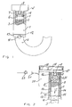
- Figure 1 is a trailer hitch according to the invention for a car shown in side view and in partial section, in which in a clutch housing 1 in a central Longitudinal bore 2 a ball rod 3 guided axially is. At the free end of the outside of the clutch housing 1 is curved ball rod 3, as in Figures 3 to 6, shown, a coupling ball 4 arranged.
- a coupling ball 4 arranged at the free end of the outside of the clutch housing 1 curved ball rod 3, as in Figures 3 to 6, shown, a coupling ball 4 arranged.
- On which the Coupling ball 4 facing away, in the longitudinal bore 2 guided end section of the ball rod 3 is a swivel joint 5 provided with an axis of rotation 6, by means of which the ball rod, as soon as they are shown in Figure 4 from the clutch housing 1 assumes the pushed-out position, can be tilted by 90 °, a remaining section 7 inside the clutch housing 1 remains.
- the clutch housing 1 is also in longitudinal section shown, but rotated by 90 °.
- the twist guide shows Ball rod 3 flattenings 14 on the inside of the cover 13 arranged guide sections 15 work together.
- the diameter of the net distance between the flats 14 corresponds, so that at the guide the anti-rotation device 14, 15 only acts until when moving the ball rod 3 in direction I the twist 16 dips into the lid 13.
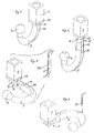
- the swivel joint is 5 completely from the longitudinal bore 2 of the clutch housing 1 surfaced while the remaining section 7 due to the the twist 16 formed federal 17 with a stroke stop the cover 13 or the guide sections 15 cooperates. This position is shown in Figure 4.
- the ball rod 3 about the axis 6th of the joint 5 can be pivoted through 90 °, then through Elimination of the twist guide 14, 15, as shown in Figure 6, after to be swung in the back.
- the Threaded spindle 9 connected to a gear 18, which in turn meshes with a gear 19 by one Electric motor 20 is drivable with the clutch housing 1 is connected.
- the electric motor 20 is connected via a cable 21 Power supplied, which is controlled by a switch 22.
- the threaded spindle 9 has only the Function to pull the ball rod 3 into the position shown and lock there in this operating position or when not Operation put the tow bar 3 on the towbar loosen so that this downwards according to arrow I can be pushed out to be tilted and pivoted afterwards to be able to.
- something different design of the transmission 9, 18, 19 the full stroke the ball rod 3 or the like by a spindle. fully automatic is made.
- FIGS. 3 to 6 The adjustment process according to the invention is shown in FIGS. 3 to 6 the towbar is explained using 4 positions.
- Figure 3 takes the ball rod 3 in the operating position in which the coupling ball 4 protrudes and in which the cross bolt 11 fits positively on the cover 13.
- the flat 14 serves as an anti-twist device.
Landscapes
- Engineering & Computer Science (AREA)
- Transportation (AREA)
- Mechanical Engineering (AREA)
- Pivots And Pivotal Connections (AREA)
- Mechanical Operated Clutches (AREA)
- Agricultural Machines (AREA)
Applications Claiming Priority (2)
| Application Number | Priority Date | Filing Date | Title |
|---|---|---|---|
| DE19947653 | 1999-10-04 | ||
| DE19947653 | 1999-10-04 |
Publications (2)
| Publication Number | Publication Date |
|---|---|
| EP1090782A2 true EP1090782A2 (fr) | 2001-04-11 |
| EP1090782A3 EP1090782A3 (fr) | 2002-02-06 |
Family
ID=7924366
Family Applications (1)
| Application Number | Title | Priority Date | Filing Date |
|---|---|---|---|
| EP00119819A Withdrawn EP1090782A3 (fr) | 1999-10-04 | 2000-09-12 | Dispositif d'attelage pour véhicules automobiles |
Country Status (2)
| Country | Link |
|---|---|
| EP (1) | EP1090782A3 (fr) |
| DE (1) | DE10045296A1 (fr) |
Cited By (9)
| Publication number | Priority date | Publication date | Assignee | Title |
|---|---|---|---|---|
| EP1225067A3 (fr) * | 2001-01-23 | 2002-08-07 | FAC Frank Abels Consulting & Technology GmbH | Attelage de remorque |
| NL1026198C2 (nl) | 2004-05-14 | 2005-11-15 | Brink Internat B V | Verdraaibare trekhaak. |
| WO2006068479A1 (fr) | 2004-12-24 | 2006-06-29 | Thule Towing Systems B.V. | Attelage de remorquage retractable |
| RU2375209C2 (ru) * | 2004-12-24 | 2009-12-10 | Туле Тауинг Системз Б.В. | Убираемая сцепка |
| EP2295268A1 (fr) * | 2000-04-05 | 2011-03-16 | SCAMBIA Industrial Developments Aktiengesellschaft | Attelage |
| EP1491369B1 (fr) | 2003-06-26 | 2019-01-16 | Bosal ACPS Holding 2 B.V. | Attelage pour vehicules |
| EP4108481A1 (fr) * | 2021-06-23 | 2022-12-28 | MVG Metallverarbeitungsgesellschaft mbH | Dispositif d'attelage |
| EP4108482A1 (fr) * | 2021-06-23 | 2022-12-28 | MVG Metallverarbeitungsgesellschaft mbH | Dispositif d'attelage destiné à être fixé à un arrière d'un véhicule |
| US11577561B2 (en) | 2017-12-20 | 2023-02-14 | Horizon Global (South Africa) (Pty) Ltd | Towbar with a hitch ball system |
Families Citing this family (8)
| Publication number | Priority date | Publication date | Assignee | Title |
|---|---|---|---|---|
| DE10354753B4 (de) * | 2003-11-21 | 2014-07-24 | Westfalia-Automotive Gmbh | Anhängekupplung für Kraftfahrzeuge |
| DE102004004503B4 (de) | 2004-01-22 | 2022-01-20 | ACPS Automotive GmbH | Anhängekupplung |
| DE102004004501B4 (de) † | 2004-01-22 | 2021-07-01 | ACPS Automotive GmbH | Anhängekupplung |
| DE102004044912A1 (de) * | 2004-09-14 | 2006-03-30 | Mvg Metallverarbeitungsgesellschaft Mbh | Anhängekupplung mit Kugelgelenk |
| EP1634730A1 (fr) | 2004-09-14 | 2006-03-15 | MVG Metallverarbeitungsgesellschaft mbH | Attelage de remorque avec articulation à rotule |
| DE502007001954D1 (de) * | 2006-09-18 | 2009-12-24 | Westfalia Automotive Gmbh | Anhängevorrichtung für ein Zugfahrzeug |
| DE102021111749B3 (de) | 2021-05-06 | 2022-04-14 | Dr. Ing. H.C. F. Porsche Aktiengesellschaft | Kraftfahrzeugkarosserie mit einer Luftleiteinrichtung und mit einer Anhängerkupplungsmontageeinrichtung und ein Verfahren für eine Kraftfahrzeugkarosserie |
| DE102021111761A1 (de) | 2021-05-06 | 2022-11-10 | Dr. Ing. H.C. F. Porsche Aktiengesellschaft | Heckanordnung für ein Fahrzeug |
Citations (3)
| Publication number | Priority date | Publication date | Assignee | Title |
|---|---|---|---|---|
| DE3541904A1 (de) | 1985-11-27 | 1987-06-04 | Daimler Benz Ag | Anhaengerkupplung fuer fahrzeuge |
| DE3718552A1 (de) | 1987-06-03 | 1988-12-15 | Oris Metallbau Kg Riehle H | Anhaengevorrichtung fuer kraftfahrzeuge, insbesondere personenkraftwagen |
| DE29520254U1 (de) | 1995-09-13 | 1996-04-11 | Cartron Fahrzeugteile GmbH, 27367 Sottrum | Anhängerkupplung für Kraftfahrzeuge |
Family Cites Families (5)
| Publication number | Priority date | Publication date | Assignee | Title |
|---|---|---|---|---|
| DE813098C (de) * | 1950-03-09 | 1951-09-06 | Franz Kaehler | Anhaengevorrichtung fuer Kraftfahrzeuganhaenger |
| FR2227739A5 (en) * | 1973-04-25 | 1974-11-22 | Gumuchian Pierre | Retracting drawgear for road type trailers - can be housed under trailer chassis when not in use |
| FR2450167A1 (fr) * | 1979-02-27 | 1980-09-26 | Oppermann Rene | Dispositif d'attelage escamotable pour remorque |
| US4792153A (en) * | 1986-09-05 | 1988-12-20 | Emmanuel Galdes | Trailer hitch |
| US4744583A (en) * | 1987-05-27 | 1988-05-17 | Lloyd Blackwood | Motorized wide range tow hitch |
-
2000
- 2000-09-12 EP EP00119819A patent/EP1090782A3/fr not_active Withdrawn
- 2000-09-12 DE DE10045296A patent/DE10045296A1/de not_active Withdrawn
Patent Citations (3)
| Publication number | Priority date | Publication date | Assignee | Title |
|---|---|---|---|---|
| DE3541904A1 (de) | 1985-11-27 | 1987-06-04 | Daimler Benz Ag | Anhaengerkupplung fuer fahrzeuge |
| DE3718552A1 (de) | 1987-06-03 | 1988-12-15 | Oris Metallbau Kg Riehle H | Anhaengevorrichtung fuer kraftfahrzeuge, insbesondere personenkraftwagen |
| DE29520254U1 (de) | 1995-09-13 | 1996-04-11 | Cartron Fahrzeugteile GmbH, 27367 Sottrum | Anhängerkupplung für Kraftfahrzeuge |
Cited By (12)
| Publication number | Priority date | Publication date | Assignee | Title |
|---|---|---|---|---|
| EP2295268A1 (fr) * | 2000-04-05 | 2011-03-16 | SCAMBIA Industrial Developments Aktiengesellschaft | Attelage |
| EP1916127B2 (fr) † | 2000-04-05 | 2016-10-26 | Scambia Holdings Cyprus Limited | Attelage |
| EP1225067A3 (fr) * | 2001-01-23 | 2002-08-07 | FAC Frank Abels Consulting & Technology GmbH | Attelage de remorque |
| EP1491369B1 (fr) | 2003-06-26 | 2019-01-16 | Bosal ACPS Holding 2 B.V. | Attelage pour vehicules |
| EP1491369B2 (fr) † | 2003-06-26 | 2025-01-15 | ACPS Automotive GmbH | Attelage pour vehicules |
| NL1026198C2 (nl) | 2004-05-14 | 2005-11-15 | Brink Internat B V | Verdraaibare trekhaak. |
| WO2006068479A1 (fr) | 2004-12-24 | 2006-06-29 | Thule Towing Systems B.V. | Attelage de remorquage retractable |
| RU2375209C2 (ru) * | 2004-12-24 | 2009-12-10 | Туле Тауинг Системз Б.В. | Убираемая сцепка |
| RU2385235C2 (ru) * | 2004-12-24 | 2010-03-27 | Туле Тауинг Системз Б.В. | Убираемая сцепка |
| US11577561B2 (en) | 2017-12-20 | 2023-02-14 | Horizon Global (South Africa) (Pty) Ltd | Towbar with a hitch ball system |
| EP4108481A1 (fr) * | 2021-06-23 | 2022-12-28 | MVG Metallverarbeitungsgesellschaft mbH | Dispositif d'attelage |
| EP4108482A1 (fr) * | 2021-06-23 | 2022-12-28 | MVG Metallverarbeitungsgesellschaft mbH | Dispositif d'attelage destiné à être fixé à un arrière d'un véhicule |
Also Published As
| Publication number | Publication date |
|---|---|
| EP1090782A3 (fr) | 2002-02-06 |
| DE10045296A1 (de) | 2001-04-05 |
Similar Documents
| Publication | Publication Date | Title |
|---|---|---|
| EP3829956B1 (fr) | Mécanisme de réglage destiné à une colonne de direction et colonne de direction pour véhicule automobile | |
| DE19654867C2 (de) | Schwenkbare Anhängerkupplung für Kraftfahrzeuge | |
| EP0597406B1 (fr) | Support réglable en hauteur, préférablement pour caravanes | |
| DE10045296A1 (de) | Anhängerkupplung für Kraftfahrzeuge | |
| EP3891042B1 (fr) | Colonne de direction pour un véhicule à moteur | |
| DE10243045B4 (de) | Anhängerkupplung | |
| EP1902871A1 (fr) | Attelage | |
| DE10243044B4 (de) | Anhängerkupplung | |
| EP1084870B1 (fr) | Dispositif d'attelage articulé à verrouillage automatique | |
| EP1535765A1 (fr) | Attelage pour véhicules | |
| DE29921859U1 (de) | Seitenfensterrollo | |
| DE20215508U1 (de) | Anhängevorrichtung für Zugfahrzeuge | |
| EP1488943B1 (fr) | Dispositif d'attelage motorisé pour véhicules | |
| DE102015007937A1 (de) | Baumaschinen zum Bearbeiten von Bodenoberflächen mit einer Schwenkvorrichtung für eine Fahreinrichtung sowie Schwenkvorrichtung für eine solche Baumaschine | |
| DE3129101A1 (de) | Laengenveraenderbare vorrichtung zum verstellen der position eines fahrzeugsitzes | |
| EP0356753A2 (fr) | Roue-support | |
| DE3442514A1 (de) | Anhaengerkupplung fuer fahrzeuge, insbesondere personenkraftfahrzeuge | |
| DE19858980C5 (de) | Fahrzeugsitz, insbesondere Kraftfahrzeugsitz, mit einer Einstellvorrichtung | |
| EP1916164A2 (fr) | Support réglable en hauteur pour caravanes | |
| EP0388363B1 (fr) | Attelage pour véhicules | |
| EP0823342B1 (fr) | Attelage de remorque | |
| DE69311381T2 (de) | Teleskopische Stütze für Anhängerdeichsel | |
| EP1586471A1 (fr) | Attelage de remorque | |
| DE102021116182A1 (de) | Anhängevorrichtung zur Anbringung an einem Heck eines Fahrzeugs | |
| DE4131858C2 (fr) |
Legal Events
| Date | Code | Title | Description |
|---|---|---|---|
| PUAI | Public reference made under article 153(3) epc to a published international application that has entered the european phase |
Free format text: ORIGINAL CODE: 0009012 |
|
| AK | Designated contracting states |
Kind code of ref document: A2 Designated state(s): AT BE CH CY DE DK ES FI FR GB GR IE IT LI LU MC NL PT SE |
|
| AX | Request for extension of the european patent |
Free format text: AL;LT;LV;MK;RO;SI |
|
| PUAL | Search report despatched |
Free format text: ORIGINAL CODE: 0009013 |
|
| AK | Designated contracting states |
Kind code of ref document: A3 Designated state(s): AT BE CH CY DE DK ES FI FR GB GR IE IT LI LU MC NL PT SE |
|
| AX | Request for extension of the european patent |
Free format text: AL;LT;LV;MK;RO;SI |
|
| AKX | Designation fees paid |
Free format text: AT BE CH CY DE DK ES FI FR GB GR IE IT LI LU MC NL PT SE |
|
| STAA | Information on the status of an ep patent application or granted ep patent |
Free format text: STATUS: THE APPLICATION IS DEEMED TO BE WITHDRAWN |
|
| 18D | Application deemed to be withdrawn |
Effective date: 20020807 |