EP1491369B2 - Attelage pour vehicules - Google Patents
Attelage pour vehicules Download PDFInfo
- Publication number
- EP1491369B2 EP1491369B2 EP04007905.5A EP04007905A EP1491369B2 EP 1491369 B2 EP1491369 B2 EP 1491369B2 EP 04007905 A EP04007905 A EP 04007905A EP 1491369 B2 EP1491369 B2 EP 1491369B2
- Authority
- EP
- European Patent Office
- Prior art keywords
- locking
- trailer coupling
- bearing element
- pivoting
- bearing
- Prior art date
- Legal status (The legal status is an assumption and is not a legal conclusion. Google has not performed a legal analysis and makes no representation as to the accuracy of the status listed.)
- Expired - Lifetime
Links
Images












Classifications
-
- B—PERFORMING OPERATIONS; TRANSPORTING
- B60—VEHICLES IN GENERAL
- B60D—VEHICLE CONNECTIONS
- B60D1/00—Traction couplings; Hitches; Draw-gear; Towing devices
- B60D1/24—Traction couplings; Hitches; Draw-gear; Towing devices characterised by arrangements for particular functions
- B60D1/246—Traction couplings; Hitches; Draw-gear; Towing devices characterised by arrangements for particular functions for actuating the hitch by powered means
-
- B—PERFORMING OPERATIONS; TRANSPORTING
- B60—VEHICLES IN GENERAL
- B60D—VEHICLE CONNECTIONS
- B60D1/00—Traction couplings; Hitches; Draw-gear; Towing devices
- B60D1/01—Traction couplings or hitches characterised by their type
- B60D1/06—Ball-and-socket hitches
-
- B—PERFORMING OPERATIONS; TRANSPORTING
- B60—VEHICLES IN GENERAL
- B60D—VEHICLE CONNECTIONS
- B60D1/00—Traction couplings; Hitches; Draw-gear; Towing devices
- B60D1/48—Traction couplings; Hitches; Draw-gear; Towing devices characterised by the mounting
- B60D1/54—Traction couplings; Hitches; Draw-gear; Towing devices characterised by the mounting collapsible or retractable when not in use, e.g. hide-away hitches
Definitions
- the invention relates to a trailer coupling for motor vehicles comprising a ball neck which carries a coupling ball at one end and a bearing element at another end, a vehicle-fixed bearing receptacle on which the bearing element with the ball neck is mounted so as to be pivotable about an axis between a working position and a rest position, a positive locking fixing device which positively fixes the bearing element relative to the bearing receptacle at least in the working position, a fixing state in which the positive locking fixing device is effective and a pivoting state in which, in the absence of any action against pivoting, unstabilized rotational positions of the bearing element are present.
- Such trailer couplings are from the EP 0 799 732 A1 known.
- the bearing element can be in an unstabilized rotational position in the swiveling state against swiveling.
- the rotational positions in the swiveling state against swiveling can be unstabilized if the drive is not self-locking.
- the bearing head can be freely pivoted about the bearing pin in the release position.
- the invention is therefore based on the object of improving a trailer coupling of the generic type in such a way that the positive locking fixing device can be reliably brought into its position effective for fixing the working position.
- a pre-positioning device which stabilizes the bearing element against further pivoting when pivoting in the direction of the working position in a rotational position representing a first end position, and that the first end position is arranged in such a way that, starting from this, a rotational position representing a first positive locking position is reached, in which a transition of the positive locking fixing device into its position effective for fixing the working position takes place.
- this pre-positioning device provides an advantageous possibility of keeping the bearing element stabilized in the first position long enough for the form-fitting fixing device to be able to be transferred into its effective position.
- claim 1 defines that there is free rotation, up to the first end position to be reached, in which the bearing head can be stabilized against pivoting by the pre-positioning device.
- the positive locking fixing device can be designed in different ways. For example, it would be conceivable to design the positive locking fixing device in such a way that elements of the positive locking fixing device are movable relative to the bearing element and/or the bearing receptacle in order to bring the positive locking fixing device into its active or inactive state.
- a particularly simple and cost-effective solution provides that the bearing element can be moved in the direction of the axis between a fixing position in which the positive locking device is effective in the fixing state and a pivoting position in which the positive locking device is ineffective.
- This solution is particularly advantageous when the positive locking device is intended to fix the bearing element relative to the bearing holder without play, since it only provides one movable element, namely the bearing element, which can be easily fixed to the bearing holder without play.
- the bearing element could be manually movable between the fixing position and the pivoting position.
- bearing element can be displaced in the direction of the axis by means of a displacement device.
- a particularly advantageous solution provides that the pre-positioning is effective in the swivel position.
- the form-locking fixing device can be brought into effect by moving the bearing element positioned in the first end position from the pivoting position to the fixing position.
- the pre-positioning device is designed such that it allows the bearing element to be moved at least over part of the path from the pivot position to the fixing position while maintaining the first end position.
- a particularly advantageous solution provides that the bearing element, when moving in the direction of the pivot axis from the fixing position to the pivot position, can be brought into a rotational position representing a first release position, starting from which the bearing element can be pivoted without being influenced by the pre-positioning device.
- This advantageous solution can be implemented, for example, by ensuring that the pre-positioning device is ineffective when the bearing element is moved from the fixing position to the pivoting position.
- an element of the pre-positioning device could be moved to an ineffective position in order to cancel the effect of the pre-positioning device when the release position is reached.
- the first release position could also be identical to the first end position.
- the first release position is a rotational position that differs from the first end position.
- the rotational position corresponding to the release position does not coincide with the rotational position corresponding to the end position and thus the influence of the pre-positioning device can be limited to the first end position, so that in the first release position the pre-positioning device no influence is present.
- the first release position is a rotational position arranged in the direction of a pivoting direction due to gravity that deviates from the first position.
- the first form-locking position and the first end position are coincident rotational positions.
- this in turn makes it more difficult to construct the first release position as a rotational position that deviates from the first end position.
- the solution according to the invention provides that the first form-locking position is a rotational position that deviates from the first end position, so that the first end position and the first form-locking position can be easily separated from one another.
- a particularly advantageous design solution provides that the form-locking position is a rotational position deviating from the first end position in the direction of a gravity-induced pivoting direction.
- a further advantageous solution provides that the release position is a rotational position arranged in the direction of the gravity-induced pivoting direction deviating from the form-locking position.
- a further advantageous embodiment of a trailer coupling according to the invention provides that the bearing element can be fixed in a rotational position representing a second end position when pivoting in the direction of the rest position with the pre-positioning device and that the second end position is arranged in such a way that, starting from this, a rotational position representing a second positive locking position can be reached, in which the positive locking fixing device can be brought into its position effective for fixing the rest position.
- the advantage of this solution is that there is also an end position that can be determined by the pre-positioning device for reaching the rest position, so that the rest position can also be reached with the advantages mentioned at the beginning in connection with the working position.
- the form-locking fixing device can be brought into effect by moving the bearing element positioned in the second end position from the pivoting position into the fixing position.
- a favorable solution provides that the pre-positioning device is designed in such a way that it allows the bearing element to be displaced at least over part of the path from the pivoting position to the fixing position while maintaining the second end position.
- the bearing element when moving in the direction of the axis from the fixing position into the pivoting position, can be brought into a rotational position representing a second release position, starting from which the bearing element can be pivoted without being influenced by the pre-positioning device.
- the second release position and the second end position it is also possible to provide that both coincide.
- the second release position is a rotational position that differs from the second end position.
- the second release position a rotational position deviating from the second end position in the direction of a gravity-induced pivoting direction.
- the second form-locking position is a rotational position that differs from the second end position.
- the second form-locking position is a rotational position that deviates from the second end position in the direction of a gravity-induced pivoting direction.
- the second release position is a rotational position that deviates from the second form-locking position in the direction of the pivoting direction due to gravity.
- the pre-positioning device as a device that stabilizes the end position of the bearing element by means of frictional engagement.
- the pre-positioning device has at least a first and a second locking element, which can be brought into operative connection to stabilize the respective end position.
- the pre-positioning has at least one further locking element which can be brought into operative connection to stabilize the bearing element in the other end position.
- one of the cooperating locking elements comprises a locking body that can be moved into and out of a locking position and the other of the cooperating locking elements is designed as a locking body receptacle that cooperates with the locking body.
- the locking body is designed to be spring-loaded and movable.
- the locking body can preferably be designed as a locking pawl or locking ball.
- Another embodiment of a pre-positioning according to the invention does not work with locking elements, but is designed in such a way that it can be brought into effect by a movement of the bearing element from the pivot position in the direction of the fixing position to a positioning position.
- the effect of the pre-positioning device could, for example, be achieved via frictional engagement.
- a particularly advantageous solution for such a pre-positioning device provides that it comprises two positioning elements that can be brought into positive engagement by the movement into the positioning position.
- the pre-positioning device is preferably designed such that it comprises a displacement unit which automatically triggers a displacement of the bearing element into the positioning position when the rotational position of the bearing element allows the bearing element to be moved into the positioning position.
- the triggering of the displacement of the bearing element into the positioning position does not only take place in a single rotational position, but the positioning device is expediently designed such that it triggers the movement of the bearing element into the positioning position when the rotational position of the bearing element is within a capture range.
- the positioning device has a control unit which controls the displacement device in order to move the bearing element into the positioning position.
- the already existing drive for moving the bearing element can also be used to transfer the bearing element from the swivel position to the positioning position and thus fix the bearing element in the respective end position.
- a particularly advantageous embodiment of a trailer coupling according to the invention further provides an alignment device with which the bearing element can be brought into the first positive locking position for the positive locking fixing device to become effective.
- Such an alignment device has the great advantage that it can be used to easily adapt the rotational position of the bearing element exactly to the required form-locking position for bringing the form-locking fixing device into operative connection, even if the end position deviates from the form-locking position.
- the alignment device is expediently designed in such a way that it allows a movement of the bearing element in the direction of the pivot axis while maintaining the first form-locking position.
- a further advantageous embodiment provides an alignment device with which the bearing element can be brought into a second positive locking position for the positive locking fixing device to become effective.
- the alignment device is preferably designed in such a way that it allows a movement of the bearing element in the direction of the fixing position while maintaining the form-locking position.
- the alignment device in relation to the pre-positioning, it is preferably provided that when the bearing element in the respective end position moves from the pivot position towards the fixing position, the alignment device becomes effective before the pre-positioning device loses its effect.
- the alignment device is designed such that when the bearing element moves from the fixing position to the pivoting position, the bearing element reaches the release position.
- the alignment device includes an alignment element and an alignment surface that can be placed on it to specify each of the form-locking positions.
- the alignment surface can be placed on the alignment element by a gravity-induced pivoting movement of the bearing element.
- the alignment surface could be a separate surface, for example provided on a projection.
- a particularly simple structural solution provides that the alignment surface is formed by a wall of a recess, such a recess extending in particular into the pivoting element.
- the alignment surface itself can be arranged locally independently of the form-locking elements.
- a structurally expedient solution provides that the alignment surface is aligned with a partial area of one of the form-locking elements. This means that the alignment surface is arranged in such a way that it represents a continuation of a partial area of a form-locking element, in particular a wall surface thereof.
- Such a solution is used in particular in all cases in which the alignment element to be applied to the alignment surface is also located on a form-locking element, is part of such a form-locking element or is embodied by the respective form-locking element itself.
- the alignment device is designed in such a way that it is only able to specify the form-locking position.
- the alignment device in such a way that the bearing element can be pivoted in the direction of the respective form-locking position with the alignment device, in particular when the bearing element is moved in the direction of the fixing position.
- the alignment device not only serves to determine the form-locking position, but can also be used to actively pivot the bearing element in order to bring it into the form-locking position.
- this is independent of the pre-positioning device.
- the alignment device in such a way that it also functions as a pre-positioning device, so that it is particularly possible to use the same elements to form both the pre-positioning device and the alignment device.
- the positive locking fixing device has at least one first positive locking element arranged on the bearing element and at least one second positive locking element arranged on the bearing receptacle and that the first and second positive locking elements can be brought into engagement with one another by a relative movement of the same in the direction of the pivot axis.
- first and second form-locking elements are designed in such a way that they can be brought into positive engagement in the respective form-locking position.
- first and the second form-locking element are designed in such a way that they can be brought into play-free engagement with one another in the respective form-locking position.
- the form-locking fixing device is designed such that the first and the second form-locking element can be brought into engagement with one another by movement of the bearing element relative to the bearing receptacle.
- the shifting device can be designed in a variety of ways.
- a particularly advantageous embodiment provides that the displacement device has a spindle and a spindle nut.
- the sliding spindle is connected to the bearing element in a rotationally fixed manner and the spindle nut Rotatable on the bearing mount, but fixed in the direction of the axis.
- the drive comprises self-locking cooperating gear elements in order to ensure that the spindle nut does not loosen in a rotational position intended for it, but remains in this position.
- the drive it is particularly advantageous if it comprises a motor, in particular an electric motor.
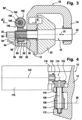
- a first embodiment of a trailer coupling according to the invention shown in Fig. 1 , comprises a vehicle-fixed bearing holder, designated as a whole by 10, with a first bearing cheek 12 and a second bearing cheek 14, which are arranged at a distance from one another and are connected to one another via a base part 16.
- a bearing shaft designated as a whole by 18, is mounted on the bearing cheeks 12 and 14 so as to be rotatable about an axis 20, wherein the bearing shaft 18 passes through the bearing cheeks 12 and 14.
- bearing shaft 18 passes through a bearing element 22 which is held at one end 24 of a ball neck designated as a whole by 26, which has a coupling ball 30 at a cranked end 28 opposite the end 24.
- the bearing shaft 18 is not only pivotably held on the bearing cheeks 12 and 14, but is also displaceable in an axial direction 32 running parallel to the axis 20, so that the bearing element 22 is also displaceable in the axial direction 32 with the bearing shaft 18.
- the displaceability of the bearing element 22 is limited in that it lies in a space 33 between the first bearing cheek 12 and the second bearing cheek 14.
- the bearing shaft 18 has a section 34 for mounting the same in the second bearing cheek 14 with a jacket surface 36 which is cylindrical to the axis 20 and which extends in the axial direction 32 so far that the bearing shaft 18 with the bearing element 22 sitting on it can be displaced in the space 33 between the bearing cheeks 12, 14 while maintaining the mounting of the same on the second bearing cheek 14, in particular can be displaced from a position essentially resting on the first bearing cheek 12 until the bearing element 22 comes to rest on the second bearing shaft 14 with a rear side 38 facing the second bearing cheek 14.
- a bearing bush 42 is provided which passes through a bearing opening 40 in the second bearing cheek 14, in which the cylindrical surface 36 is guided so as to be rotatable about the axis 20 and displaceable in the axial direction 32.
- the bearing shaft 18 has a section 44 with a cylindrical outer surface 46, with which the bearing shaft 18 in a bearing opening 50 in the bearing bush 52 passing through the first bearing cheek 12 is guided so as to be rotatable about the axis 20 and displaceable in the axial direction 32.
- the bearing shaft 18 is connected to the bearing element 22 in a rotationally fixed manner with respect to the axis 20 and also immovably in the axial direction 32, wherein the bearing shaft 18 preferably rests against the rear side 38 with a collar 54, so that a defined relative position of the bearing shaft 18 to the bearing element 22 is predetermined.
- a form-locking fixing device designated as a whole by 60, which comprises at least a first form-locking element 62 provided on the bearing element 22, preferably designed as a recess, and a second form-locking element 64 provided on the first bearing cheek 12, for example in the form of a projection, wherein the projection 64 can be brought into engagement with the first form-locking element 62, for example by the projection 64 engaging in the receptacle 62.
- the second form-locking element 64 is formed, for example, by a pin 66 which is inserted into a corresponding bore 68 in the first bearing cheek 12 and projects beyond an inner side 70 of the first bearing cheek 12 facing the bearing element 22.
- the first form-locking element 62 is preferably designed as a recess extending from a front side 72 opposite the rear side 38 into the bearing element 22, wherein when the form-locking fixing device 60 is effective, the front side 72 of the bearing element 22 is preferably close to the inner side 70 of the first bearing cheek 12.
- the form-locking fixing device 60 is designed such that the form-locking elements 62 and 64 engage with one another without play, in particular when the bearing element 22 is subjected to a force K which presses the form-locking elements 62 and 64 into engagement and in the process presses, for example, a conical region 76 of the second form-locking element 64 into a conical region 74 of the first form-locking element 62.
- Fig. 2 The position shown is referred to as the fixing position F in the context of the present invention and the force K is preferably determined by a Fig. 2 schematically illustrated and designated as a whole by 80, which acts on the bearing shaft 18 in order to thereby displace the bearing element 22 sitting on it.
- the bearing element 22 can also be moved into a Fig. 2 pivot position S shown in dashed lines, in which its rear side 38 is close to the second bearing cheek 14 and the form-locking elements 62 and 64 are disengaged, so that the bearing element 22 and with it the entire ball neck 26 are unhindered by the form-locking elements 62 and 64 and thus freely pivotable about the pivot axis 20.
- the displacement device 80 can be designed in a variety of ways. One possibility is to design the displacement device in accordance with the European patent application 1 142 732 A1 Another embodiment provides for the displacement device 80 to be designed in accordance with the European patent application 1 288 026 A1 to train.
- a further embodiment of a displacement device 80' according to the invention comprises a section of the bearing shaft 18 which is arranged on a side of the first bearing cheek 12 opposite the bearing element 22 and extends beyond the latter, which section is provided with an external thread 84 to form a spindle 82, which in turn engages in an internal thread 86 of a spindle nut 88 and penetrates the spindle nut 88.
- the spindle nut 88 has an end face 90 facing the first bearing cheek 12, which rests on an outer surface 92 of the first bearing cheek 12 facing away from the bearing element 22. Furthermore, the spindle nut 88 has, on its side opposite the end face 90, an end face 94 which rests against a wall surface 96 of a projection 98, which in turn is arranged on a support region 99 of the bearing receptacle 10 connected to the first bearing cheek 12, so that the spindle nut 88 is guided immovably in the axial direction 32 between the outer surface 92 of the first bearing cheek 12 and the wall surface 96 of the projection 98, the spindle nut 88 being rotatably mounted relative to the axis 20 by the bearing shaft 18 itself, so that overall the spindle nut 88 is floatingly mounted by the bearing shaft 18 and is fixed immovably relative to the bearing receptacle 10 in the axial direction 32.
- the latter can be driven by a drive 100 which has a drive toothing 102 arranged on the spindle nut 88, which is designed, for example, as a worm toothing which can be brought into engagement with a drive worm 104.
- the drive worm 104 is in turn located on a Drive shaft 106 of the drive 100, which is rotatably mounted on the bearing holder 10 about a shaft axis 108, for example such that the drive worm 104 sits between two bearing flanges 110 and 112 of the bearing holder 10, in which the drive shaft 106 is then rotatably mounted.
- the drive shaft 106 preferably extends through one of the bearing flanges, namely the bearing flange 110, and is coupled to a drive motor 116 of the drive 100 via a gear 114.
- the drive motor 116 is preferably an electric motor, which in turn is firmly connected to the bearing holder 10 by means of a motor holder 118.
- the gear 114 of the drive 100 is a bevel gear comprising two bevel gears 120 and 122, but it is also conceivable to design the gear 114 as a different type of deflection gear, for example as a worm gear or any other type of deflection gear.
- the gear 114 is designed such that a motor axis 124 can extend transversely to the shaft axis 108.
- the advantage of using the drive worm 104 in conjunction with the drive gearing 102 on the spindle nut 88 is that such a worm gear 126 provided in the drive 100 is self-locking and thus any rotary movement of the spindle nut 88 is blocked when the drive motor 116 is at a standstill.
- the invention is based on a trailer coupling of the type described, in which in the swivel position S, shown in dashed lines in Fig. 2 and presented in Fig. 5 the ball neck 26 with the bearing element 22 rotates due to the effect of gravity on it in such a way that the ball neck 26 hangs downwards in the pivot position S and the coupling ball 30 is held close to a road surface, so that the ball neck 26 in Fig. 1 has left the working position shown.
- the ball neck 26 with the bearing element 22 can be freely rotated in the pivot position S of the bearing element 22 together with the bearing shaft 18.
- a drive which can, however, be rotated by the ball neck 26 when gravity acts on it.
- the trailer coupling is provided with a pre-positioning device 130 which comprises a first locking element 132 which is fixedly arranged on the bearing holder 10 and a second locking element 134a which is also fixedly arranged on the bearing element 22.
- the first locking element 132 is, as in Fig. 8 shown, for example, as a ball pressure screw 136, which comprises a screw body 138 in which a locking ball 140 is guided in a receiving bore 142 and is acted upon by a compression spring 144, which is also arranged in the receiving bore 142, in the direction of a locking position protruding beyond the receiving bore 142, wherein the locking ball 140 has the possibility of moving from the locking position into the receiving bore 142 against the action of the compression spring 144.
- a ball pressure screw 136 which comprises a screw body 138 in which a locking ball 140 is guided in a receiving bore 142 and is acted upon by a compression spring 144, which is also arranged in the receiving bore 142, in the direction of a locking position protruding beyond the receiving bore 142, wherein the locking ball 140 has the possibility of moving from the locking position into the receiving bore 142 against the action of the compression spring 144.
- Such a ball pressure screw 136 is held, for example, with an arm 146 on the bearing holder 10, preferably on the base part 16 thereof.
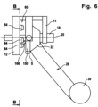
- the second locking element 134a is, as in Fig. 5 and 7 shown, a V-shaped locking recess 134a arranged in a circumferential region 150 of the bearing element 22 having the maximum radial distance from the axis 20, which is formed by locking bumps 152a and 152b arranged on both sides of the locking recess 134a, wherein the locking bumps 152a, b still project radially to the axis 20 beyond the circumferential region 150.
- a further second locking element 134b is provided on the bearing element 22, which is designed in the same way as the locking element 134a and also lies between two locking bumps 152a, 152b.
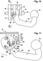
- the first locking element 134a is arranged according to the invention on the bearing element 22 in such a way that when pivoting in a pivoting direction 156 opposite to a gravity-induced pivoting direction 154, the locking elements 132 and 134a are in a Fig. 9 to 11 come into operative connection with one another in the first end position Ea shown, wherein in this first end position Ea the locking ball 140 engages in the V-shaped locking recess 134a, whereby the ball neck 26 can be fixed in the first end position Ea, although the bearing element 22 is in the pivot position and is thus not fixed by the form-fitting fixing device 60.
- the first end position Ea which is defined by the interacting locking elements 132 and 134a, is, for example, as in Fig. 11 shown, arranged so that the form-locking elements 62 are moved in the pivoting direction 156 beyond a rotational position congruent with the second form-locking elements 64, i.e. a first form-locking position FSa, so that, for example, in this first end position, the form-locking elements 62, 64 are rotated relative to one another by a small angular distance, but lie essentially directly next to one another.
- a Fig. 9 to 11 shown alignment device 160 which has two alignment elements 162 and 164, wherein the alignment element 162, for example, is provided in the bearing element 62 and also already in Fig. 7 shown recess, while the alignment element 164 is, for example, a pin extending from the first bearing cheek 12, which extends approximately parallel to the axial direction 32 in the direction of the bearing element 22 in such a way that it extends with an end region 166 beyond the form-locking elements 64, as in Fig. 10 and also already in Fig. 6 shown.
- the locking elements 132 and 134a are now designed such that the bearing element 22 can be held in the end position and can be moved in this end position 22 by the displacement device 80 in the direction of the first bearing cheek 12 without first leaving the first end position Ea.
- the alignment elements 162 and 164 are arranged relative to one another in such a way that the alignment element 164 can come into engagement with the alignment element 162 in the first end position Ea with the end region 166 before the form-locking elements 64 touch the front side 72 of the bearing element 22.
- the locking elements 132 and 134 are designed in such a way that they lose their effect when the alignment device 160 is fully effective, as shown in the Fig. 12 to 15 shown.
- the bearing element 22 and the ball neck 26 are fully under the effect of gravity and have the tendency to move in the direction of the gravity-induced pivoting direction 154, whereby this movement is only possible to the extent that the alignment element 162 permits.
- the alignment element 162 is designed such that it has end walls 168a, 168b arranged at an angular distance from one another, which limit a rotational movement of the bearing element 22 about the axis 20.
- the alignment element 164 in the end position such that it dips into the alignment element 162a formed as a recess near the end wall 168a, while the end wall 168b is arranged at an angular distance relative to the axis 20 from the alignment element 168, as in Fig.
- the first end position Ea of the ball neck 26 with the bearing element 22 is selected such that in this position the form-locking elements 62 and 64 do not engage, but are arranged close to one another, i.e. at a small angular distance from one another.
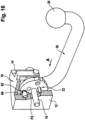
- the alignment device 160 defines when the alignment element 164 rests with the end region 166 on the end wall 168b, as in the Fig. 16 to 18 shown, a rotational position of the bearing element 22 and the ball neck 26, in which the form-locking elements 62 and 64 are aligned with each other, but without initially engaging with each other.
- This rotational position of the bearing element 22 is referred to as the first form-locking position FSa determined by the alignment device 160.
- the first form-locking position FSa shown is maintained as long as the alignment elements 162a and 164 are in engagement, wherein in particular the alignment element 164 rests with its end region 166 on the end wall 168b of the alignment element 162.
- FIG. 19 shows that the bearing element 22 is displaced by the maximum possible distance in the axial direction 32 in the direction of the first bearing cheek 12 in order to achieve the Fig. 1 and 2 explained play-free fixation of the bearing element 22 relative to the bearing holder 10.
- the displacement device 80 not only makes it possible to move the bearing element 22 with the ball neck 26 into the Fig. 1, 2 and 19 shown fixing position F, but also the possibility to move it from the fixing position F in the direction of the Fig. 2
- the first form-locking position FSa is initially maintained by the alignment device 160 and the bearing element 22 with the ball neck 26 is only in a first release position FGa and can be freely pivoted about the axis 20 from there when the alignment device 160 with the alignment elements 162a and 164 have lost their effect, that is, the alignment element 164 has become disengaged from the alignment element 162a.
- the bearing element 22 with the ball neck 24 can again be pivoted in the direction of the gravity-related pivoting direction 154, so that under the effect of gravity it can be pivoted into the Fig. 5 to 7 shown rotational position.
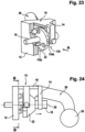
- the form-locking elements 62 and 64 are arranged in such a way that they are not in the second form-locking position FSb and are therefore not aligned with one another, but are at a small angular distance from one another.
- the alignment elements 162b and 164 are aligned with each other in such a way that they are aligned with each other to the extent that the alignment element 164 can be brought into engagement with the alignment element 162a.
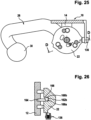
- the pre-positioning device 130 becomes ineffective ( Fig. 26 ) and is therefore no longer able to prevent a rotational movement of the bearing element 22.
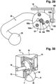
- the alignment element 162b is now designed in the same way as the alignment element 162a, so that the ball neck 26 and the bearing element 22 have the possibility of moving in the direction of the gravity-induced pivoting direction 174, namely until the end region 166 of the alignment element 164 rests against the end wall 168b, as in Fig. 27 to 29 , wherein the alignment device 160 has alignment elements 162b and 164 arranged such that the form-locking elements 62 and 64 are again in a mutually aligned form-locking position FSb.
- the second form-locking position FSb assigned to the rest position R is offset by 120° from the first form-locking position FSa assigned to the working position A, then if there are three form-locking elements 62, 64 arranged at the same angular distance from one another, the same form-locking elements can also be used for the form-locking fixation of the rest position R. If the pivoting angle between the form-locking position assigned to the rest position R and the form-locking position facing the working position A deviates from 120°, then additional form-locking elements 62 must be provided for the form-locking fixation in the rest position R, which are located next to the form-locking elements 62 provided for the working position A, preferably arranged at an angular distance from them.
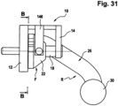
- the displacement device 80 can now be used as in Fig. 30 to 33 shown, to move the bearing element 22 completely in the direction of the first bearing cheek 12 into the fixing position F, in which a play-free fixing of the bearing element 22 in the rest position R takes place.
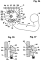
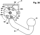
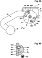
- the alignment device 160' is also formed by a recess 162' in the bearing element 22, but the recess 162' is arranged such that it covers the first form-locking element 62 in the bearing element 22 and extends in the direction of gravity movement 154 starting from the first form-locking element 62a provided for the form-locking fixation in the working position.
- the second form-locking element 64 can also simultaneously form the alignment element 164', since this alignment element 164' can penetrate into the alignment element 162' in the first end position EA, although the first form-locking position FSa has not yet been reached.
- the bearing element 22 Immediately after the pre-positioning device 130 has lost its effect, as for example in Fig. 37 shown, the bearing element 22 has the possibility to pivot in the direction of the gravity-induced pivoting direction 154 and this leads to the alignment element 164' coming to rest on the end wall 168'a of the alignment element 162' ( Fig. 38 ).
- the end wall 168'a is in alignment with the part of the first form-locking element 62 adjoining it, so that when the alignment element 164' and thus also the first form-locking element 64 rest against the end wall 168'a, the second form-locking element 64 and the first form-locking element 62 in form-locking position.
- first form-locking elements 62a and 62b are provided, wherein the first form-locking element 62a is assigned to the working position and the first form-locking element 62b is assigned to the rest position.
- the alignment element 162' extends as a recess from the first form-locking element 62a to the first form-locking element 62b and completely covers both, the end wall 168'a of the alignment element 162' being aligned with a portion of the first form-locking element 62a facing away from the other first form-locking element 62b and the end wall 168'b being aligned with a portion of the first form-locking element 62b facing away from the other first form-locking element 62a, so that each of the end walls 168'a and 168'b defines a form-locking position, namely the end wall 168'a the first form-locking position and the end wall 168'b the second form-locking position.
- the pre-positioning device 130" and the alignment device 160" are formed by other elements, namely on the one hand by a locking element 180 designed as a locking ball 182, which is arranged in a ball pressure screw 192, which in turn is arranged in the bearing element 22 in a receptacle 184, so that only the locking ball 180 protrudes beyond an outer contour 186 of the bearing element 22.
- the detent ball 182 cooperates with a groove system 190a in a body 192 that extends over the outer contour 186 of the bearing element 22, and to reach the rest position R, it cooperates with a groove system 190b in the body 192.
- the groove systems 190a and 190b are in principle identical.
- the groove systems 190a and 190b comprise a free movement section 194 in which the locking ball 182 moves unhindered, provided that the ball neck 26 is in the downwardly hanging position under the effect of gravity, in Fig. 5 to 7 shown position.
- the sections 198a and 198b of the groove systems 190a and 190b thus form the pre-positioning device 130" together with the locking ball 182, which can engage in each of these groove sections 198a and 198b.
- the bearing element 22 In order to move from the pre-positioning device 130" to the alignment device 160", the bearing element 22 must be displaced in a direction 200 toward the first bearing cheek 12 in the same way as described in connection with the first embodiment.
- the locking ball 182 By moving the bearing element 22 in the direction 200, the locking ball 182 also moves from the groove sections 198a and 198b into the groove sections 202a and 202b of the groove systems 190a and 190b, which together with the locking ball 182 form the alignment device 160', which leads to an alignment of the bearing element 22 such that the form-locking elements 62, 64 can be brought into engagement with one another.
- the alignment device 160' is effective until the fixing position F is reached and also in this position.
- the groove sections 198a and 202a or 198b and 202b are separated by a branching point 204a and 204b, in which two groove sections, namely the groove sections 198a and 198b and the groove sections 206a and 206b branch off, the latter leading into the open-air section 194.
- the locking ball 182 migrates along the groove sections 202a and 202b of the alignment device 160' and then, starting from the groove branch 204a and 204b, into the groove sections 206a and 206b due to the force of gravity acting on the ball neck 26 and thus ends in the free movement section 194, in which the locking ball 182 does not prevent movement of the ball neck 26 and the bearing element 22 in the direction of the pivoting direction due to gravity, but allows this movement freely, so that the ball neck 26 can be moved into the Fig. 5 to 7 shown rotational position falls downwards and the bearing element 22 also rotates accordingly.
- the ball neck 26 together with the pivoting element 22 can be pivoted again so that the locking ball 182 either engages with the groove section 198a in order to reach the working position, or with the groove section 198b in order to reach the form-locking position FS associated with the working position or the rest position when the bearing element 22 is displaced in the direction 200, in which the form-locking elements 62, 64 can be brought into engagement with one another.
Landscapes
- Engineering & Computer Science (AREA)
- Transportation (AREA)
- Mechanical Engineering (AREA)
- Mounting Of Bearings Or Others (AREA)
Claims (53)
- Attelage pour des véhicules automobiles comprenant un col de boule d'attelage (26), qui porte à une extrémité (28) une boule d'attelage (30) et à une autre extrémité (24) un élément de palier (22), un logement de palier (10) fixé au véhicule au niveau duquel l'élément de palier (22) est logé de manière pivotante avec le col de boule d'attelage (26) autour d'un axe (20) entre une position de travail (A) et une position de repos (R), un dispositif de fixation à complémentarité de formes (60) qui fixe à complémentarité de formes l'élément de palier (22) par rapport au logement de palier (10) au moins dans la position de travail (A), un état de fixation dans lequel le dispositif de fixation à complémentarité de formes (60) est actif et un état de pivotement dans lequel, en cas de non-action contre un pivotement, des positions de rotation de l'élément de palier (22) non stabilisées sont présentes,
caractérisé en ce qu'un dispositif de prépositionnement (130) est prévu, lequel stabilise l'élément de palier (22) lors du pivotement en direction de la position de travail (A) dans une position de rotation représentant une première position d'extrémité (Ea) contre un autre pivotement, et que la première position d'extrémité (Ea) est agencée de telle manière qu'à partir de celle-ci une position de rotation représentant une première position à complémentarité de formes (FSa) soit atteinte, dans laquelle une transition du dispositif de fixation à complémentarité de formes (60) dans sa position active pour la fixation de la position de travail (A) est effectuée et en ce que la première position à complémentarité de formes (FSa) est une position de rotation divergeant de la première position d'extrémité (Ea). - Attelage selon la revendication 1, caractérisé en ce que l'élément de palier (22) est mobile entre une position de fixation (F) dans laquelle le dispositif de fixation à complémentarité de formes (60) est actif dans l'état de fixation, et une position de pivotement (S) dans laquelle le dispositif de fixation à complémentarité de formes (60) est inactif, en direction (32) de l'axe (20).
- Attelage selon la revendication 1, caractérisé en ce que l'élément de palier (22) est mobile par un dispositif de déplacement (80) en direction (32) de l'axe (20).
- Attelage selon l'une quelconque des revendications précédentes, caractérisé en ce que le dispositif de prépositionnement (130) est actif dans la position de pivotement (S).
- Attelage selon l'une quelconque des revendications précédentes, caractérisé en ce que le dispositif de fixation à complémentarité de formes (60) peut être amené en action par le déplacement de l'élément de palier (22) positionné dans la première position d'extrémité (Ea) de la position de pivotement (S) à la position de fixation (F).
- Attelage selon la revendication 5, caractérisé en ce que le dispositif de prépositionnement (130) est réalisé de telle manière que celui-ci autorise, au moins sur une partie de la course de la position de pivotement (S) dans la position de fixation (F), le déplacement de l'élément de palier (22) en conservant la première position d'extrémité (Ea).
- Attelage selon l'une quelconque des revendications précédentes, caractérisé en ce que l'élément de palier (22) peut être amené, lors du déplacement en direction de l'axe (20) de la position de fixation (F) dans la position de pivotement (S), dans une position de rotation représentant une première position de libération (FGa), à partir de laquelle l'élément de palier (22) peut pivoter sans influence du dispositif de prépositionnement (130).
- Attelage selon la revendication 7, caractérisé en ce que la première position de libération (FGa) est une position de rotation divergeant de la première position d'extrémité (Ea).
- Attelage selon la revendication 7 ou 8, caractérisé en ce que la première position de libération (FGa) est une position de rotation agencée en direction d'une direction de pivotement (154) soumise à la force de gravité divergeant de la première position d'extrémité (Ea).
- Attelage selon l'une quelconque des revendications précédentes, caractérisé en ce que la première position à complémentarité de formes (FSa) est une position de rotation agencée en direction d'une direction de pivotement (154) soumise à la force de gravité divergeant de la première position d'extrémité (Ea).
- Attelage selon l'une quelconque des revendications 7 à 10, caractérisé en ce que la première position de libération (FGa) est une position de rotation agencée en direction de la direction de pivotement (154) soumise à la force de gravité divergeant de la première position à complémentarité de formes (FSa).
- Attelage selon l'une quelconque des revendications précédentes, caractérisé en ce qu'avec le dispositif de prépositionnement (130) l'élément de palier (22) peut être fixé, lors du pivotement en direction de la position de repos (R), dans une position de rotation représentant une seconde position d'extrémité (Eb), et que la seconde position d'extrémité (Eb) est agencée de telle manière qu'à partir de celle-ci une position de rotation représentant une seconde position à complémentarité de formes (FSb) puisse être atteinte dans laquelle le dispositif de fixation à complémentarité de formes (60) peut être amené dans sa position active pour la fixation de la position de repos (R).
- Attelage selon la revendication 12, caractérisé en ce que le dispositif de fixation à complémentarité de formes (60) peut être amené en action par le déplacement de l'élément de palier (22) positionné dans la seconde position d'extrémité (Eb) de la position de pivotement (S) à la position de fixation.
- Attelage selon la revendication 13, caractérisé en ce que le dispositif de prépositionnement (130) est réalisé de telle manière que celui-ci autorise, au moins sur une partie de la course de la position de pivotement (S) à la position de fixation (F), le déplacement de l'élément de palier (22) en conservant la seconde position d'extrémité (Eb).
- Attelage selon l'une quelconque des revendications précédentes, caractérisé en ce que l'élément de palier (22) peut être amené, lors du déplacement en direction de l'axe (20) de la position de fixation (F) à la position de pivotement (S), dans une position de rotation représentant une seconde position de libération (FGb), à partir de laquelle l'élément de palier (22) peut être pivoté sans influence du dispositif de prépositionnement (130).
- Attelage selon la revendication 15, caractérisé en ce que la seconde position de libération (FGb) est une position de rotation divergeant de la seconde position d'extrémité (Eb).
- Attelage selon la revendication 16, caractérisé en ce que la seconde position de libération (FGb) est une position de rotation agencée en direction d'une direction de pivotement soumise à la force de gravité divergeant de la seconde position d'extrémité (Eb).
- Attelage selon l'une quelconque des revendications 12 à 17, caractérisé en ce que la seconde position à complémentarité de formes (FSb) est une position de rotation divergeant de la seconde position d'extrémité (Eb).
- Attelage selon la revendication 18, caractérisé en ce que la seconde position à complémentarité de formes (FSb) est une position de rotation agencée en direction d'une direction de pivotement soumise à la force de gravité divergeant de la seconde position d'extrémité (Eb).
- Attelage selon l'une quelconque des revendications 12 à 19, caractérisé en ce que la seconde position de libération (FGb) est une position de rotation agencée en direction de la direction de pivotement soumise à la force de gravité divergeant de la seconde position à complémentarité de formes (FSb).
- Attelage selon l'une quelconque des revendications précédentes, caractérisé en ce que le dispositif de prépositionnement (130) stabilise la position d'extrémité (Ea, Eb) respective de l'élément de palier (22) par liaison à complémentarité de formes.
- Attelage selon la revendication 21, caractérisé en ce que le dispositif de prépositionnement (130) présente au moins un premier et au moins un second élément d'encliquetage (132, 134a, 190, 190a) qui peuvent être amenés en liaison active pour la stabilisation de la position d'extrémité (Ea, Eb) respective.
- Attelage selon la revendication 22, caractérisé en ce que le dispositif de prépositionnement (130) présente au moins un autre élément d'encliquetage (134b, 190b) qui peut être amené en liaison active pour la stabilisation de l'élément de palier (22) dans l'autre position d'extrémité (Eb, Ea).
- Attelage selon la revendication 22 ou 23, caractérisé en ce qu'un des éléments d'encliquetage (132, 180) coopérants comprend un corps d'encliquetage (140, 182) mobile dans une position d'encliquetage et hors de celle-ci et l'autre des éléments d'encliquetage coopérants est réalisé en tant que logement de corps d'encliquetage (134a, b ; 190a, b) coopérant avec le corps d'encliquetage (140, 182).
- Attelage selon la revendication 24, caractérisé en ce que le corps d'encliquetage (140, 182) est réalisé de manière mobile par sollicitation par ressort.
- Attelage selon la revendication 24 ou 25, caractérisé en ce que le corps d'encliquetage est réalisé en tant que cliquet d'encliquetage.
- Attelage selon la revendication 25, caractérisé en ce que le corps d'encliquetage est réalisé en tant que boule d'encliquetage (140, 182).
- Attelage selon l'une quelconque des revendications 1 à 20, caractérisé en ce que le dispositif de prépositionnement (130ʺʺ) peut être amené en action par un déplacement de l'élément de palier (22) de la position de pivotement (S) en direction de la position de fixation (F) jusqu'à une position de positionnement (P).
- Attelage selon la revendication 28, caractérisé en ce que le dispositif de prépositionnement (130ʺʺ) comprend deux éléments de positionnement (224, 228) pouvant être mis en prise à complémentarité de formes par le déplacement dans la position de positionnement (P).
- Attelage selon la revendication 28 ou 29, caractérisé en ce que le dispositif de prépositionnement (130ʺʺ) comprend une unité de déplacement (80) qui déclenche automatiquement un déplacement de l'élément de palier (22) dans la position de positionnement (P) lorsque la position de rotation de l'élément de palier (22) autorise un déplacement de l'élément de palier (22) dans la position de positionnement (P).
- Attelage selon la revendication 30, caractérisé en ce que le dispositif de prépositionnement (130ʺʺ) déclenche le déplacement de l'élément de palier (22) dans la position de positionnement (P) lorsque la position de rotation de l'élément de palier (22) se trouve dans une zone de capture (WB).
- Attelage selon l'une quelconque des revendications 28 à 31, caractérisé en ce que le dispositif de prépositionnement (130ʺʺ) présente une unité de commande (226) qui commande le dispositif de déplacement (80) pour le déplacement de l'élément de palier (22) dans la position de positionnement (P).
- Attelage selon l'une quelconque des revendications précédentes, caractérisé en ce qu'un dispositif d'orientation (160) est prévu, avec lequel l'élément de palier (22) peut être amené pour la mise en action du dispositif de fixation à complémentarité de formes (60) dans la première position à complémentarité de formes (FSa).
- Attelage selon la revendication 33, caractérisé en ce que le dispositif d'orientation (160) est réalisé de telle manière qu'il autorise, en conservant la première position à complémentarité de formes (FSa), un déplacement de l'élément de palier (22) en direction (32) de la position de fixation (F).
- Attelage selon l'une quelconque des revendications précédentes, caractérisé en ce qu'un dispositif d'orientation (160) est prévu, avec lequel l'élément de palier (22) peut être amené pour la mise en action du dispositif de fixation à complémentarité de formes (60) dans la seconde position à complémentarité de formes (FSb).
- Attelage selon la revendication 35, caractérisé en ce que le dispositif d'orientation (160) est réalisé de telle manière qu'il autorise, en conservant la seconde position à complémentarité de formes (FSb), un déplacement de l'élément de palier (22) en direction (32) de la position de fixation (F).
- Attelage selon l'une quelconque des revendications 33 à 36, caractérisé en ce que, lors d'un déplacement de l'élément de palier (22) se trouvant dans la position d'extrémité (Ea, Eb) respective de la position de pivotement (S) en direction de la position de fixation (F), le dispositif d'orientation (160) est actif avant que le dispositif de prépositionnement (130) ne perde son action.
- Attelage selon l'une quelconque des revendications 33 à 37, caractérisé en ce que le dispositif d'orientation (160) est réalisé de telle manière que, lors de la transition de l'élément de palier (22) de la position de fixation (F) dans la position de pivotement (S), l'élément de palier (22) atteint la position de libération (FG).
- Attelage selon l'une quelconque des revendications 33 à 38, caractérisé en ce que le dispositif d'orientation (160) comprend, pour la prédéfinition de chacune des positions à complémentarité de formes (FS), un élément d'orientation (164, 162) et une surface d'orientation (168, 202a, b) pouvant être posée sur celui-ci.
- Attelage selon la revendication 39, caractérisé en ce que la surface d'orientation (168, 202a, b) peut être posée par un déplacement de pivotement soumis à la force de gravité de l'élément de palier (22) contre l'élément d'orientation (164, 182).
- Attelage selon l'une quelconque des revendications 33 à 40, caractérisé en ce que la surface d'orientation (168, 168', 168ʺʺ, 202a, b, 228) est formée par une paroi d'un évidement (162, 162', 162ʺʺ, 202a, b, 62).
- Attelage selon l'une quelconque des revendications 33 à 40, caractérisé en ce que la surface d'orientation (168, 168', 168"", 228) s'aligne sur une zone partielle d'un élément à complémentarité de formes (62) du dispositif de fixation à complémentarité de formes (60).
- Attelage selon l'une quelconque des revendications 33 à 42, caractérisé en ce que l'élément de palier (22) peut pivoter avec le dispositif d'orientation (160', 160ʺʺ) en direction de la position à complémentarité de formes (FS) respective.
- Attelage selon l'une quelconque des revendications 33 à 41, caractérisé en ce que le dispositif d'orientation (160ʺʺ) est actif aussi en tant que dispositif de prépositionnement (130'''').
- Attelage selon l'une quelconque des revendications précédentes, caractérisé en ce que le dispositif de fixation à complémentarité de formes (60) présente au moins un premier (62), agencé au niveau de l'élément de palier (22), et au moins un second, agencé au niveau du logement de palier (10), élément à complémentarité de formes (64) et que le premier (62) et le second élément à complémentarité de formes (64) peuvent venir en prise l'un avec l'autre par un déplacement relatif de ceux-ci en direction (32) de l'axe de pivotement (20).
- Attelage selon la revendication 45, caractérisé en ce que le premier et le second élément à complémentarité de formes (62, 64) sont réalisés de telle manière que ceux-ci puissent être mis en prise à complémentarité de formes dans la position à complémentarité de formes (FS) respective.
- Attelage selon la revendication 46, caractérisé en ce que le premier et le second élément à complémentarité de formes (62, 64) sont réalisés de telle manière que ceux-ci puissent venir en prise sans jeu l'un avec l'autre dans la position à complémentarité de formes (FS) respective.
- Attelage selon l'une quelconque des revendications précédentes, caractérisé en ce que le dispositif de fixation à complémentarité de formes (60) est réalisé de sorte que, par le déplacement de l'élément de palier (22) par rapport au logement de palier (10), le premier et le second élément à complémentarité de formes (62, 64) puissent venir en prise l'un avec l'autre.
- Attelage selon l'une quelconque des revendications 3 à 48, caractérisé en ce que le dispositif de déplacement (80) présente une broche (82) et un écrou de broche (88).
- Attelage selon la revendication 49, caractérisé en ce que la broche (82) est raccordée de manière fixe en rotation à l'élément de palier (22) et l'écrou de broche (88) est logé de manière rotative au niveau du logement de palier (10), toutefois de manière immobile en direction (32) de l'axe (20).
- Attelage selon la revendication 50, caractérisé en ce que l'écrou de broche (88) peut être entraîné par un entraînement (100).
- Attelage selon la revendication 51, caractérisé en ce que l'entraînement (100) comprend des éléments d'engrenage (126) coopérant par autoblocage.
- Attelage selon la revendication 51 ou 52, caractérisé en ce que l'entraînement (100) comprend un moteur (116).
Applications Claiming Priority (2)
| Application Number | Priority Date | Filing Date | Title |
|---|---|---|---|
| DE10329622A DE10329622A1 (de) | 2003-06-26 | 2003-06-26 | Anhängekupplung |
| DE10329622 | 2003-06-26 |
Publications (3)
| Publication Number | Publication Date |
|---|---|
| EP1491369A1 EP1491369A1 (fr) | 2004-12-29 |
| EP1491369B1 EP1491369B1 (fr) | 2019-01-16 |
| EP1491369B2 true EP1491369B2 (fr) | 2025-01-15 |
Family
ID=33395053
Family Applications (1)
| Application Number | Title | Priority Date | Filing Date |
|---|---|---|---|
| EP04007905.5A Expired - Lifetime EP1491369B2 (fr) | 2003-06-26 | 2004-04-01 | Attelage pour vehicules |
Country Status (2)
| Country | Link |
|---|---|
| EP (1) | EP1491369B2 (fr) |
| DE (1) | DE10329622A1 (fr) |
Families Citing this family (13)
| Publication number | Priority date | Publication date | Assignee | Title |
|---|---|---|---|---|
| DE202004010806U1 (de) * | 2004-07-10 | 2004-10-21 | Westfalia-Automotive Gmbh & Co. Kg | Anhängerkupplung für Kraftfahrzeuge |
| RU2375209C2 (ru) * | 2004-12-24 | 2009-12-10 | Туле Тауинг Системз Б.В. | Убираемая сцепка |
| US8136803B2 (en) | 2007-01-15 | 2012-03-20 | Phd, Inc. | Armover clamp assembly |
| DE102008034851A1 (de) * | 2008-06-06 | 2009-12-17 | Westfalia-Automotive Gmbh | Anhängekupplung |
| DE102011053506A1 (de) * | 2011-09-12 | 2013-03-14 | Scambia Holdings Cyprus Ltd. | Anhängekupplung |
| DE102017118152B4 (de) * | 2017-08-09 | 2020-09-24 | Fac Frank Abels Consulting & Technology Gesellschaft Mbh | Motorisch verschwenkbare Anhängekupplung |
| DE102018124518A1 (de) * | 2018-10-04 | 2020-04-09 | ACPS Automotive GmbH | Anhängekupplung |
| DE102019109398B4 (de) * | 2019-04-10 | 2021-05-27 | Dr. Ing. H.C. F. Porsche Aktiengesellschaft | Anhängerkupplung |
| DE102019129346A1 (de) * | 2019-10-30 | 2021-05-06 | ACPS Automotive GmbH | Anhängekupplung |
| DE112020004480A5 (de) * | 2019-11-29 | 2022-06-15 | Westfalia-Automotive Gmbh | Anhängekupplung mit einem schwenkbaren Kupplungsarm |
| DE102020111469A1 (de) * | 2020-04-27 | 2021-10-28 | ACPS Automotive GmbH | Anhängekupplung |
| CN116373513B (zh) * | 2021-05-20 | 2025-07-01 | 浙江致优汽车科技有限公司 | 可自锁的电动拖车钩装置 |
| CN116142142B (zh) * | 2023-03-22 | 2026-01-30 | 吉泰车辆技术(苏州)有限公司 | 位置自适应的车辆电池包用换电小车 |
Citations (17)
| Publication number | Priority date | Publication date | Assignee | Title |
|---|---|---|---|---|
| FR2450167A1 (fr) † | 1979-02-27 | 1980-09-26 | Oppermann Rene | Dispositif d'attelage escamotable pour remorque |
| FR2476554A1 (fr) † | 1978-11-28 | 1981-08-28 | Durnerin Jeanne | Perfectionnement aux dispositifs d'attache a des vehicules tracteurs dont les automobiles de remorque et caravane |
| DE3328524A1 (de) † | 1983-08-06 | 1985-02-21 | Daimler-Benz Ag, 7000 Stuttgart | Anhaengerkupplung fuer fahrzeuge |
| US5322313A (en) † | 1993-04-29 | 1994-06-21 | Schroeder Robert D | Multiple connector trailer hitch |
| DE19521896A1 (de) † | 1995-06-16 | 1997-01-30 | Oris Fahrzeugteile Riehle H | Anhängevorrichtung für insbesondere Personenkraftwagen |
| DE19826618A1 (de) † | 1998-06-17 | 1999-12-23 | Peter Rocca | Anhängekupplung |
| DE19858978A1 (de) † | 1998-12-19 | 2000-06-29 | Daimler Chrysler Ag | Schwenkbare Anhängerkupplung für Kraftfahrzeuge |
| DE19859961A1 (de) † | 1998-12-29 | 2000-07-13 | Westfalia Werke Gmbh & Co | Anhängerkupplung mit einem schwenkbaren Kugelhals |
| EP1084870A2 (fr) † | 1999-09-15 | 2001-03-21 | Jaeger Cartronix GmbH | Dispositif d'attelage articulé à verrouillage automatique |
| EP1090782A2 (fr) † | 1999-10-04 | 2001-04-11 | PEKA-Fahrzeugbau GmbH & Co. KG | Dispositif d'attelage pour véhicules automobiles |
| WO2001032451A1 (fr) † | 1999-10-29 | 2001-05-10 | Wing Enterprises, Inc. | Systeme d'attelage convertible, pivotant, et suspendu |
| DE10004523A1 (de) † | 2000-02-02 | 2001-08-09 | Fac Frank Abels Consult & Tech | Anhängerkupplung |
| EP1142732A2 (fr) † | 2000-04-05 | 2001-10-10 | ORIS FAHRZEUGTEILE HANS RIEHLE GmbH | Attelage de remorque |
| EP1288026A1 (fr) † | 2001-09-03 | 2003-03-05 | ORIS FAHRZEUGTEILE HANS RIEHLE GmbH | Attelage de remorque |
| DE10243044A1 (de) † | 2002-09-12 | 2004-05-13 | Fac Frank Abels Consulting & Technology Gesellschaft Mbh | Anhängerkupplung |
| EP1428697A1 (fr) † | 2002-11-13 | 2004-06-16 | Westfalia Automotive GmbH & Co. KG | Dipositif d'attelage |
| EP1475253A1 (fr) † | 2003-05-07 | 2004-11-10 | Westfalia Automotive GmbH & Co. KG | Attelage de remorque pour véhicules automobiles |
Family Cites Families (2)
| Publication number | Priority date | Publication date | Assignee | Title |
|---|---|---|---|---|
| FR2614242B1 (fr) | 1987-04-24 | 1989-07-21 | Peugeot | Dispositif de fixation d'un crochet de remorquage sur un vehicule automobile. |
| DE10117656A1 (de) | 2000-04-10 | 2002-01-03 | Eberhardt Peka Fahrzeug | Wegschwenkkupplung |
-
2003
- 2003-06-26 DE DE10329622A patent/DE10329622A1/de not_active Withdrawn
-
2004
- 2004-04-01 EP EP04007905.5A patent/EP1491369B2/fr not_active Expired - Lifetime
Patent Citations (17)
| Publication number | Priority date | Publication date | Assignee | Title |
|---|---|---|---|---|
| FR2476554A1 (fr) † | 1978-11-28 | 1981-08-28 | Durnerin Jeanne | Perfectionnement aux dispositifs d'attache a des vehicules tracteurs dont les automobiles de remorque et caravane |
| FR2450167A1 (fr) † | 1979-02-27 | 1980-09-26 | Oppermann Rene | Dispositif d'attelage escamotable pour remorque |
| DE3328524A1 (de) † | 1983-08-06 | 1985-02-21 | Daimler-Benz Ag, 7000 Stuttgart | Anhaengerkupplung fuer fahrzeuge |
| US5322313A (en) † | 1993-04-29 | 1994-06-21 | Schroeder Robert D | Multiple connector trailer hitch |
| DE19521896A1 (de) † | 1995-06-16 | 1997-01-30 | Oris Fahrzeugteile Riehle H | Anhängevorrichtung für insbesondere Personenkraftwagen |
| DE19826618A1 (de) † | 1998-06-17 | 1999-12-23 | Peter Rocca | Anhängekupplung |
| DE19858978A1 (de) † | 1998-12-19 | 2000-06-29 | Daimler Chrysler Ag | Schwenkbare Anhängerkupplung für Kraftfahrzeuge |
| DE19859961A1 (de) † | 1998-12-29 | 2000-07-13 | Westfalia Werke Gmbh & Co | Anhängerkupplung mit einem schwenkbaren Kugelhals |
| EP1084870A2 (fr) † | 1999-09-15 | 2001-03-21 | Jaeger Cartronix GmbH | Dispositif d'attelage articulé à verrouillage automatique |
| EP1090782A2 (fr) † | 1999-10-04 | 2001-04-11 | PEKA-Fahrzeugbau GmbH & Co. KG | Dispositif d'attelage pour véhicules automobiles |
| WO2001032451A1 (fr) † | 1999-10-29 | 2001-05-10 | Wing Enterprises, Inc. | Systeme d'attelage convertible, pivotant, et suspendu |
| DE10004523A1 (de) † | 2000-02-02 | 2001-08-09 | Fac Frank Abels Consult & Tech | Anhängerkupplung |
| EP1142732A2 (fr) † | 2000-04-05 | 2001-10-10 | ORIS FAHRZEUGTEILE HANS RIEHLE GmbH | Attelage de remorque |
| EP1288026A1 (fr) † | 2001-09-03 | 2003-03-05 | ORIS FAHRZEUGTEILE HANS RIEHLE GmbH | Attelage de remorque |
| DE10243044A1 (de) † | 2002-09-12 | 2004-05-13 | Fac Frank Abels Consulting & Technology Gesellschaft Mbh | Anhängerkupplung |
| EP1428697A1 (fr) † | 2002-11-13 | 2004-06-16 | Westfalia Automotive GmbH & Co. KG | Dipositif d'attelage |
| EP1475253A1 (fr) † | 2003-05-07 | 2004-11-10 | Westfalia Automotive GmbH & Co. KG | Attelage de remorque pour véhicules automobiles |
Also Published As
| Publication number | Publication date |
|---|---|
| DE10329622A1 (de) | 2005-01-20 |
| EP1491369B1 (fr) | 2019-01-16 |
| EP1491369A1 (fr) | 2004-12-29 |
Similar Documents
| Publication | Publication Date | Title |
|---|---|---|
| EP0850147B2 (fr) | Dispositif d'attelage de remorque pour vehicules automobiles | |
| EP0380974B1 (fr) | Meuleuse avec un adaptateur pour la fixation d'un outil supplémentaire | |
| EP3141406B1 (fr) | Attelage | |
| EP2261066B1 (fr) | Dispositif de remorque | |
| EP1491369B2 (fr) | Attelage pour vehicules | |
| DE102004004503B4 (de) | Anhängekupplung | |
| EP2567835B1 (fr) | Attelage | |
| EP3904128B1 (fr) | Accouplement de remorque | |
| DE3104707C2 (de) | Einstellvorrichtung für eine in axialer Richtung verstell- und einstellbare Lenksäule für Kraftfahrzeuge | |
| DE102020111468A1 (de) | Anhängekupplung | |
| EP3815936A1 (fr) | Crochet d'attelage | |
| DE10331002A1 (de) | Mitnehmer für einen Kraftfahrzeugfensterheber | |
| EP1535765A1 (fr) | Attelage pour véhicules | |
| DE19944082A1 (de) | Schwenkbare Anhängerkupplung mit selbsttätiger Verriegelung | |
| DE3322551C2 (de) | Zwischenstück zum Ausschalten der Seitenbeweglichkeit von Unterlenkern eines Ackerschleppers | |
| EP1544003B1 (fr) | Dispositif d'attelage pour véhicules automobiles | |
| DE2712645C2 (de) | Kreiselmähwerk mit einer Konditioniereinrichtung | |
| EP1197357A1 (fr) | Attelage de remorque | |
| DE3108745C2 (de) | Kraftbetätigtes Spannfutter | |
| DE102005056837A1 (de) | Einrichtung zum Befestigen eines fahrerseitigen Airbagmoduls in einem Fahrzeug | |
| EP4108482A1 (fr) | Dispositif d'attelage destiné à être fixé à un arrière d'un véhicule | |
| EP4108481B1 (fr) | Dispositif d'attelage | |
| DE102005061254B4 (de) | Fahrzeugsitz | |
| EP2671739A2 (fr) | Système d'actionnement pour un attelage de véhicule automobile | |
| DE3420219C2 (de) | Notantrieb für eine Verstelleinrichtung eines Fahrzeugsitzes |
Legal Events
| Date | Code | Title | Description |
|---|---|---|---|
| PUAI | Public reference made under article 153(3) epc to a published international application that has entered the european phase |
Free format text: ORIGINAL CODE: 0009012 |
|
| AK | Designated contracting states |
Kind code of ref document: A1 Designated state(s): AT BE BG CH CY CZ DE DK EE ES FI FR GB GR HU IE IT LI LU MC NL PL PT RO SE SI SK TR |
|
| AX | Request for extension of the european patent |
Extension state: AL HR LT LV MK |
|
| 17P | Request for examination filed |
Effective date: 20050331 |
|
| AKX | Designation fees paid |
Designated state(s): AT BE BG CH CY CZ DE DK EE ES FI FR GB GR HU IE IT LI LU MC NL PL PT RO SE SI SK TR |
|
| RAP1 | Party data changed (applicant data changed or rights of an application transferred) |
Owner name: SCAMBIA INDUSTRIAL DEVELOPMENTS AKTIENGESELLSCHAFT |
|
| 17Q | First examination report despatched |
Effective date: 20070613 |
|
| RAP1 | Party data changed (applicant data changed or rights of an application transferred) |
Owner name: SCAMBIA HOLDINGS CYPRUS LIMITED |
|
| STAA | Information on the status of an ep patent application or granted ep patent |
Free format text: STATUS: EXAMINATION IS IN PROGRESS |
|
| RAP1 | Party data changed (applicant data changed or rights of an application transferred) |
Owner name: BOSAL ACPS HOLDING 2 B.V. |
|
| REG | Reference to a national code |
Ref country code: DE Ref legal event code: R079 Ref document number: 502004015762 Country of ref document: DE Free format text: PREVIOUS MAIN CLASS: B60D0001540000 Ipc: B60D0001240000 |
|
| GRAP | Despatch of communication of intention to grant a patent |
Free format text: ORIGINAL CODE: EPIDOSNIGR1 |
|
| STAA | Information on the status of an ep patent application or granted ep patent |
Free format text: STATUS: GRANT OF PATENT IS INTENDED |
|
| RIC1 | Information provided on ipc code assigned before grant |
Ipc: B60D 1/54 19900101ALI20180716BHEP Ipc: B60D 1/06 19680901ALI20180716BHEP Ipc: B60D 1/24 19900101AFI20180716BHEP |
|
| INTG | Intention to grant announced |
Effective date: 20180731 |
|
| GRAS | Grant fee paid |
Free format text: ORIGINAL CODE: EPIDOSNIGR3 |
|
| GRAA | (expected) grant |
Free format text: ORIGINAL CODE: 0009210 |
|
| STAA | Information on the status of an ep patent application or granted ep patent |
Free format text: STATUS: THE PATENT HAS BEEN GRANTED |
|
| REG | Reference to a national code |
Ref country code: DE Ref legal event code: R081 Ref document number: 502004015762 Country of ref document: DE Owner name: ACPS AUTOMOTIVE GMBH, DE Free format text: FORMER OWNER: ORIS FAHRZEUGTEILE HANS RIEHLE GMBH, 71696 MOEGLINGEN, DE |
|
| AK | Designated contracting states |
Kind code of ref document: B1 Designated state(s): AT BE BG CH CY CZ DE DK EE ES FI FR GB GR HU IE IT LI LU MC NL PL PT RO SE SI SK TR |
|
| REG | Reference to a national code |
Ref country code: GB Ref legal event code: FG4D Free format text: NOT ENGLISH |
|
| REG | Reference to a national code |
Ref country code: CH Ref legal event code: EP Ref country code: CH Ref legal event code: PK Free format text: BERICHTIGUNGEN |
|
| REG | Reference to a national code |
Ref country code: IE Ref legal event code: FG4D Free format text: LANGUAGE OF EP DOCUMENT: GERMAN |
|
| REG | Reference to a national code |
Ref country code: DE Ref legal event code: R096 Ref document number: 502004015762 Country of ref document: DE |
|
| RIC2 | Information provided on ipc code assigned after grant |
Ipc: B60D 1/24 20060101AFI20180716BHEP Ipc: B60D 1/54 20060101ALI20180716BHEP Ipc: B60D 1/06 20060101ALI20180716BHEP |
|
| REG | Reference to a national code |
Ref country code: AT Ref legal event code: REF Ref document number: 1089447 Country of ref document: AT Kind code of ref document: T Effective date: 20190215 |
|
| REG | Reference to a national code |
Ref country code: NL Ref legal event code: MP Effective date: 20190116 |
|
| PG25 | Lapsed in a contracting state [announced via postgrant information from national office to epo] |
Ref country code: NL Free format text: LAPSE BECAUSE OF FAILURE TO SUBMIT A TRANSLATION OF THE DESCRIPTION OR TO PAY THE FEE WITHIN THE PRESCRIBED TIME-LIMIT Effective date: 20190116 |
|
| PG25 | Lapsed in a contracting state [announced via postgrant information from national office to epo] |
Ref country code: FI Free format text: LAPSE BECAUSE OF FAILURE TO SUBMIT A TRANSLATION OF THE DESCRIPTION OR TO PAY THE FEE WITHIN THE PRESCRIBED TIME-LIMIT Effective date: 20190116 Ref country code: PL Free format text: LAPSE BECAUSE OF FAILURE TO SUBMIT A TRANSLATION OF THE DESCRIPTION OR TO PAY THE FEE WITHIN THE PRESCRIBED TIME-LIMIT Effective date: 20190116 Ref country code: PT Free format text: LAPSE BECAUSE OF FAILURE TO SUBMIT A TRANSLATION OF THE DESCRIPTION OR TO PAY THE FEE WITHIN THE PRESCRIBED TIME-LIMIT Effective date: 20190516 Ref country code: ES Free format text: LAPSE BECAUSE OF FAILURE TO SUBMIT A TRANSLATION OF THE DESCRIPTION OR TO PAY THE FEE WITHIN THE PRESCRIBED TIME-LIMIT Effective date: 20190116 Ref country code: SE Free format text: LAPSE BECAUSE OF FAILURE TO SUBMIT A TRANSLATION OF THE DESCRIPTION OR TO PAY THE FEE WITHIN THE PRESCRIBED TIME-LIMIT Effective date: 20190116 |
|
| PG25 | Lapsed in a contracting state [announced via postgrant information from national office to epo] |
Ref country code: GR Free format text: LAPSE BECAUSE OF FAILURE TO SUBMIT A TRANSLATION OF THE DESCRIPTION OR TO PAY THE FEE WITHIN THE PRESCRIBED TIME-LIMIT Effective date: 20190417 Ref country code: BG Free format text: LAPSE BECAUSE OF FAILURE TO SUBMIT A TRANSLATION OF THE DESCRIPTION OR TO PAY THE FEE WITHIN THE PRESCRIBED TIME-LIMIT Effective date: 20190416 |
|
| RAP2 | Party data changed (patent owner data changed or rights of a patent transferred) |
Owner name: ACPS AUTOMOTIVE GMBH |
|
| REG | Reference to a national code |
Ref country code: DE Ref legal event code: R026 Ref document number: 502004015762 Country of ref document: DE |
|
| PLBI | Opposition filed |
Free format text: ORIGINAL CODE: 0009260 |
|
| PLAX | Notice of opposition and request to file observation + time limit sent |
Free format text: ORIGINAL CODE: EPIDOSNOBS2 |
|
| PG25 | Lapsed in a contracting state [announced via postgrant information from national office to epo] |
Ref country code: DK Free format text: LAPSE BECAUSE OF FAILURE TO SUBMIT A TRANSLATION OF THE DESCRIPTION OR TO PAY THE FEE WITHIN THE PRESCRIBED TIME-LIMIT Effective date: 20190116 Ref country code: IT Free format text: LAPSE BECAUSE OF FAILURE TO SUBMIT A TRANSLATION OF THE DESCRIPTION OR TO PAY THE FEE WITHIN THE PRESCRIBED TIME-LIMIT Effective date: 20190116 Ref country code: RO Free format text: LAPSE BECAUSE OF FAILURE TO SUBMIT A TRANSLATION OF THE DESCRIPTION OR TO PAY THE FEE WITHIN THE PRESCRIBED TIME-LIMIT Effective date: 20190116 Ref country code: SK Free format text: LAPSE BECAUSE OF FAILURE TO SUBMIT A TRANSLATION OF THE DESCRIPTION OR TO PAY THE FEE WITHIN THE PRESCRIBED TIME-LIMIT Effective date: 20190116 Ref country code: EE Free format text: LAPSE BECAUSE OF FAILURE TO SUBMIT A TRANSLATION OF THE DESCRIPTION OR TO PAY THE FEE WITHIN THE PRESCRIBED TIME-LIMIT Effective date: 20190116 |
|
| 26 | Opposition filed |
Opponent name: WESTFALIA - AUTOMOTIVE GMBH Effective date: 20191011 |
|
| REG | Reference to a national code |
Ref country code: CH Ref legal event code: PL |
|
| REG | Reference to a national code |
Ref country code: BE Ref legal event code: MM Effective date: 20190430 |
|
| GBPC | Gb: european patent ceased through non-payment of renewal fee |
Effective date: 20190416 |
|
| PG25 | Lapsed in a contracting state [announced via postgrant information from national office to epo] |
Ref country code: MC Free format text: LAPSE BECAUSE OF FAILURE TO SUBMIT A TRANSLATION OF THE DESCRIPTION OR TO PAY THE FEE WITHIN THE PRESCRIBED TIME-LIMIT Effective date: 20190116 Ref country code: LU Free format text: LAPSE BECAUSE OF NON-PAYMENT OF DUE FEES Effective date: 20190401 |
|
| REG | Reference to a national code |
Ref country code: DE Ref legal event code: R082 Ref document number: 502004015762 Country of ref document: DE Representative=s name: HOEGER, STELLRECHT & PARTNER PATENTANWAELTE MB, DE Ref country code: DE Ref legal event code: R081 Ref document number: 502004015762 Country of ref document: DE Owner name: ACPS AUTOMOTIVE GMBH, DE Free format text: FORMER OWNER: BOSAL ACPS HOLDING 2 B.V., VIANEN, NL |
|
| PG25 | Lapsed in a contracting state [announced via postgrant information from national office to epo] |
Ref country code: GB Free format text: LAPSE BECAUSE OF NON-PAYMENT OF DUE FEES Effective date: 20190416 Ref country code: LI Free format text: LAPSE BECAUSE OF NON-PAYMENT OF DUE FEES Effective date: 20190430 Ref country code: CH Free format text: LAPSE BECAUSE OF NON-PAYMENT OF DUE FEES Effective date: 20190430 |
|
| PG25 | Lapsed in a contracting state [announced via postgrant information from national office to epo] |
Ref country code: SI Free format text: LAPSE BECAUSE OF FAILURE TO SUBMIT A TRANSLATION OF THE DESCRIPTION OR TO PAY THE FEE WITHIN THE PRESCRIBED TIME-LIMIT Effective date: 20190116 Ref country code: BE Free format text: LAPSE BECAUSE OF NON-PAYMENT OF DUE FEES Effective date: 20190430 |
|
| PLBB | Reply of patent proprietor to notice(s) of opposition received |
Free format text: ORIGINAL CODE: EPIDOSNOBS3 |
|
| PG25 | Lapsed in a contracting state [announced via postgrant information from national office to epo] |
Ref country code: TR Free format text: LAPSE BECAUSE OF FAILURE TO SUBMIT A TRANSLATION OF THE DESCRIPTION OR TO PAY THE FEE WITHIN THE PRESCRIBED TIME-LIMIT Effective date: 20190116 |
|
| PG25 | Lapsed in a contracting state [announced via postgrant information from national office to epo] |
Ref country code: IE Free format text: LAPSE BECAUSE OF NON-PAYMENT OF DUE FEES Effective date: 20190401 |
|
| REG | Reference to a national code |
Ref country code: AT Ref legal event code: MM01 Ref document number: 1089447 Country of ref document: AT Kind code of ref document: T Effective date: 20190401 |
|
| PG25 | Lapsed in a contracting state [announced via postgrant information from national office to epo] |
Ref country code: AT Free format text: LAPSE BECAUSE OF NON-PAYMENT OF DUE FEES Effective date: 20190401 |
|
| PLCK | Communication despatched that opposition was rejected |
Free format text: ORIGINAL CODE: EPIDOSNREJ1 |
|
| APAH | Appeal reference modified |
Free format text: ORIGINAL CODE: EPIDOSCREFNO |
|
| APBM | Appeal reference recorded |
Free format text: ORIGINAL CODE: EPIDOSNREFNO |
|
| APBP | Date of receipt of notice of appeal recorded |
Free format text: ORIGINAL CODE: EPIDOSNNOA2O |
|
| PG25 | Lapsed in a contracting state [announced via postgrant information from national office to epo] |
Ref country code: CY Free format text: LAPSE BECAUSE OF FAILURE TO SUBMIT A TRANSLATION OF THE DESCRIPTION OR TO PAY THE FEE WITHIN THE PRESCRIBED TIME-LIMIT Effective date: 20190116 |
|
| PG25 | Lapsed in a contracting state [announced via postgrant information from national office to epo] |
Ref country code: HU Free format text: LAPSE BECAUSE OF FAILURE TO SUBMIT A TRANSLATION OF THE DESCRIPTION OR TO PAY THE FEE WITHIN THE PRESCRIBED TIME-LIMIT; INVALID AB INITIO Effective date: 20040401 |
|
| PGFP | Annual fee paid to national office [announced via postgrant information from national office to epo] |
Ref country code: CZ Payment date: 20210401 Year of fee payment: 18 Ref country code: FR Payment date: 20210423 Year of fee payment: 18 |
|
| APBQ | Date of receipt of statement of grounds of appeal recorded |
Free format text: ORIGINAL CODE: EPIDOSNNOA3O |
|
| PG25 | Lapsed in a contracting state [announced via postgrant information from national office to epo] |
Ref country code: CZ Free format text: LAPSE BECAUSE OF NON-PAYMENT OF DUE FEES Effective date: 20220401 |
|
| REG | Reference to a national code |
Ref country code: DE Ref legal event code: R081 Ref document number: 502004015762 Country of ref document: DE Owner name: ACPS AUTOMOTIVE GMBH, DE Free format text: FORMER OWNER: ACPS AUTOMOTIVE GMBH, 71706 MARKGROENINGEN, DE |
|
| RAP4 | Party data changed (patent owner data changed or rights of a patent transferred) |
Owner name: ACPS AUTOMOTIVE GMBH |
|
| PG25 | Lapsed in a contracting state [announced via postgrant information from national office to epo] |
Ref country code: FR Free format text: LAPSE BECAUSE OF NON-PAYMENT OF DUE FEES Effective date: 20220430 |
|
| P01 | Opt-out of the competence of the unified patent court (upc) registered |
Effective date: 20230517 |
|
| PGFP | Annual fee paid to national office [announced via postgrant information from national office to epo] |
Ref country code: DE Payment date: 20230420 Year of fee payment: 20 |
|
| REG | Reference to a national code |
Ref country code: DE Ref legal event code: R071 Ref document number: 502004015762 Country of ref document: DE |
|
| APBU | Appeal procedure closed |
Free format text: ORIGINAL CODE: EPIDOSNNOA9O |
|
| PUAH | Patent maintained in amended form |
Free format text: ORIGINAL CODE: 0009272 |
|
| STAA | Information on the status of an ep patent application or granted ep patent |
Free format text: STATUS: PATENT MAINTAINED AS AMENDED |
|
| 27A | Patent maintained in amended form |
Effective date: 20250115 |
|
| AK | Designated contracting states |
Kind code of ref document: B2 Designated state(s): AT BE BG CH CY CZ DE DK EE ES FI FR GB GR HU IE IT LI LU MC NL PL PT RO SE SI SK TR |
|
| REG | Reference to a national code |
Ref country code: DE Ref legal event code: R102 Ref document number: 502004015762 Country of ref document: DE |
|
| P04 | Withdrawal of opt-out of the competence of the unified patent court (upc) registered |
Free format text: CASE NUMBER: APP_22408/2025 Effective date: 20250512 |