EP1091057A2 - Schornsteinanordnung - Google Patents
Schornsteinanordnung Download PDFInfo
- Publication number
- EP1091057A2 EP1091057A2 EP00650144A EP00650144A EP1091057A2 EP 1091057 A2 EP1091057 A2 EP 1091057A2 EP 00650144 A EP00650144 A EP 00650144A EP 00650144 A EP00650144 A EP 00650144A EP 1091057 A2 EP1091057 A2 EP 1091057A2
- Authority
- EP
- European Patent Office
- Prior art keywords
- flue
- fireplace
- blocks
- chimney
- chimney assembly
- Prior art date
- Legal status (The legal status is an assumption and is not a legal conclusion. Google has not performed a legal analysis and makes no representation as to the accuracy of the status listed.)
- Granted
Links
Images




Classifications
-
- E—FIXED CONSTRUCTIONS
- E04—BUILDING
- E04F—FINISHING WORK ON BUILDINGS, e.g. STAIRS, FLOORS
- E04F17/00—Vertical ducts; Channels, e.g. for drainage
- E04F17/02—Vertical ducts; Channels, e.g. for drainage for carrying away waste gases, e.g. flue gases; Building elements specially designed therefor, e.g. shaped bricks or sets thereof
- E04F17/023—Vertical ducts; Channels, e.g. for drainage for carrying away waste gases, e.g. flue gases; Building elements specially designed therefor, e.g. shaped bricks or sets thereof made of masonry, concrete or other stone-like material; Insulating measures and joints therefor
Definitions
- the present invention relates to free-standing chimney assemblies of the type comprising a number of prefabricated components assembled together to form a fireplace communicating by a combustion gases vent hole with a vertically arranged gas flue.
- Such prefabricated assemblies are used extensively in buildings and particularly in buildings such as timber-frame buildings and the like. It is known, for example, in timber-frame buildings to build up free-standing chimney assemblies by conventional blocks and mortar. Such free-standing chimney assemblies are banned for use with party walls within timber framed housing because of poor quality control in erecting the chimney. Even when they do comply with building regulations they have the problem that very often the chimneys are not vertical in that it is almost impossible to build them sufficiently accurately by conventional means and to provide a chimney assembly that is structurally sound. This is one of the main reasons why free-standing chimney assemblies are provided where the components comprise a number of relatively large prefabricated components assembled together.
- prefabricated chimney assemblies have not heretofore been particularly successful. They have either been very difficult to assemble or alternatively, have not been sufficiently rigid in use. Further, what is required is a free-standing chimney assembly that can be made in many configurations. Thus, for example, it should be possible to have a free-standing chimney assembly that forms part of the outer wall of the house in which case the free-standing chimney assembly may encompass only one fireplace. In other situations, it should form an interior wall of the house which is often the most preferable construction, which chimney, being incorporated in the interior wall of the house, would almost certainly be required to provide two fireplaces for back to back rooms in the house.
- the present invention is directed towards providing such a construction of free-standing chimney assembly, which will be relatively easy to assemble, structurally rigid and which will integrate conveniently into the surrounding structures such as the walls of the house or the party wall between two houses.
- the invention provides such a free-standing chimney assembly of the type comprising a number of prefabricated components assembled together to form a fireplace communicating by a combustion gases vent hole with a vertically arranged gas flue, characterised in that:
- the advantage of having this assembly is that it is relatively easy to assemble and it will form a vertical and rigid structure.
- the flue pipes are surrounded by an insulation material.
- the one-piece fireplace enclosure forms two separate fireplaces with a common back wall and parallel flues
- the flue pipes adjacent the combustion gases vent provide a transition bend in the flue so that the parallel flues are moved through a right angle between the fireplace and the top of the chimney
- intermediate flue blocks are mounted between the main flue blocks having a pair of side-by-side block bores and in which the intermediate main flue block has a block bore to accommodate the two flues.
- a longitudinally arranged open air vent slot is formed in the main flue block bore.
- vent slots equi-spaced circumferentially around the block bore. This is a particularly useful construction.
- the connecting means comprises:
- each of the flue blocks and the sides of the fireplace include a laterally projecting wall anchorage rib having an end face and two side faces, the side faces forming supports for spaced apart wall panels. This allows the party walls to be easily mounted adjacent the chimney assembly thus providing a very rigid unit.
- the components are manufactured from a light-weight concrete.
- Light-weight concrete is particularly suitable because it allows for ease of assembly and the relatively light weight minimises difficulties in manipulating the components and placing them one on top of the other.
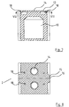
- a free-standing chimney assembly indicated generally by the reference numeral 1 comprising a one-piece fireplace 2, an inner flue member formed by a pair of sets of inner flue pipes 3 over the fireplace 2 and surrounded by a main support structure formed by upper main flue blocks 4 and intermediate main flue blocks 5. External cladding 6 and a chimney plate 7 are illustrated, these do not form part of the invention. Heat insulation material 8 is shown in Fig. 3 surrounding the inner flue pipes 3.
- the fireplace 2 comprises a one piece enclosure forming two separate fireplaces with a common back wall 10, base 11, top 12 and side walls 13. Mounted in each top wall 12 is a combustion gases vent hole 14. A laterally projecting rectangular wall anchorage rib 15 having an end face 16 and a pair of side faces 17 projects from each side wall 13. Holes 18 are provided in the top 12 for reception and anchorage of threaded sockets, not shown.
- Each intermediate main flue block 5 is a substantially octagonal block having a hollow block bore 20, top 21 and bottom face 23 and side faces 24, through-holes 25 having enlarged bores at their proximal and distal ends form socket retaining recesses 26 at the top face 21 and the bottom face 23.
- FIGs. 13 to 15 inclusive which illustrates the main flue block 4 parts similar to those described with reference to the previous drawings are identified by the same reference numerals.
- the main flue block 4 has a pair of block bores 30 communicating between top and bottom faces 31 and 32, respectively, the internal diameter of the block bore 30 is greater than the outside diameter of each inner flue member 3.
- Four longitudinally arranged open-air vent slots 33 are provided equi-spaced around the block bore 30.
- Through-holes 25 and respective recess 26 are again provided as are the ribs 15.
- a connecting means indicated generally by the reference numeral 40 for securing the chimney assembly in position, said connecting means 40 comprising a plurality of sets of interconnected tie-bars 41 having adjacent each end threads 42 for reception of an internally threaded sleeve connector 43.
- a pair of inner flue pipes 3 are mounted in the combustion gases vent holes 14 and some of the inner flue pipes 3 are so-configured as to provide a 45° bend in each flue so that the parallel flues are moved through 90° between the fireplace and the top of the chimney.
- Intermediate flue blocks 5 are then mounted on the fireplace assembly 2 and tie-bars 40 are mounted in the fireplace assembly 2 and some of the intermediate blocks 5 are formed one on top of each other and are grouted into position. Then the tie-bars 40 are tightened together by means of the sleeve connectors 42.
- a number of main flue blocks 4 are then placed in position.
- FIG. 3 shows the building of a party wall 50 formed from two panels 51 mounted against the side faces 17 of the rib 15 sandwiching insulation panels 52 therebetween.
- the chimney assembly according to the invention is manufactured from a light weight concrete.
Landscapes
- Engineering & Computer Science (AREA)
- Architecture (AREA)
- Civil Engineering (AREA)
- Structural Engineering (AREA)
- Chimneys And Flues (AREA)
- Incineration Of Waste (AREA)
- Applications Or Details Of Rotary Compressors (AREA)
- Percussion Or Vibration Massage (AREA)
Applications Claiming Priority (2)
| Application Number | Priority Date | Filing Date | Title |
|---|---|---|---|
| IE990836 | 1999-10-08 | ||
| IE990836 | 1999-10-08 |
Publications (3)
| Publication Number | Publication Date |
|---|---|
| EP1091057A2 true EP1091057A2 (de) | 2001-04-11 |
| EP1091057A3 EP1091057A3 (de) | 2001-11-28 |
| EP1091057B1 EP1091057B1 (de) | 2007-05-02 |
Family
ID=11042138
Family Applications (1)
| Application Number | Title | Priority Date | Filing Date |
|---|---|---|---|
| EP00650144A Expired - Lifetime EP1091057B1 (de) | 1999-10-08 | 2000-10-09 | Schornsteinanordnung |
Country Status (4)
| Country | Link |
|---|---|
| EP (1) | EP1091057B1 (de) |
| AT (1) | ATE361403T1 (de) |
| DE (1) | DE60034640D1 (de) |
| IE (2) | IES20000814A2 (de) |
Cited By (5)
| Publication number | Priority date | Publication date | Assignee | Title |
|---|---|---|---|---|
| GB2361524A (en) * | 2000-03-23 | 2001-10-24 | Dunbrik | Flue system |
| GB2368385A (en) * | 1999-12-23 | 2002-05-01 | Dunbrik | Flue block |
| GB2382130A (en) * | 2001-11-03 | 2003-05-21 | Red Bank Mfg Company Ltd | A gas flue assembly with laterally spaced supports with guide means |
| GB2358457B (en) * | 1999-12-23 | 2004-07-28 | Dunbrik | Gas flue block system |
| RU167693U1 (ru) * | 2016-04-20 | 2017-01-10 | федеральное государственное бюджетное образовательное учреждение высшего образования "Донской государственный технический университет" (ДГТУ) | Вентиляционный блок |
Family Cites Families (2)
| Publication number | Priority date | Publication date | Assignee | Title |
|---|---|---|---|---|
| GB567066A (en) * | 1943-02-04 | 1945-01-26 | John Charles Snelling | Improvements in or relating to fire-places and chimneys of buildings |
| US4616457A (en) * | 1985-10-04 | 1986-10-14 | Kemstone Manufacturing, Inc. | Enhanced safety flue construction |
-
2000
- 2000-10-09 IE IE20000814A patent/IES20000814A2/en not_active IP Right Cessation
- 2000-10-09 IE IE20000815A patent/IE20000815A1/en not_active IP Right Cessation
- 2000-10-09 EP EP00650144A patent/EP1091057B1/de not_active Expired - Lifetime
- 2000-10-09 DE DE60034640T patent/DE60034640D1/de not_active Expired - Lifetime
- 2000-10-09 AT AT00650144T patent/ATE361403T1/de not_active IP Right Cessation
Cited By (7)
| Publication number | Priority date | Publication date | Assignee | Title |
|---|---|---|---|---|
| GB2368385A (en) * | 1999-12-23 | 2002-05-01 | Dunbrik | Flue block |
| GB2358457B (en) * | 1999-12-23 | 2004-07-28 | Dunbrik | Gas flue block system |
| GB2368385B (en) * | 1999-12-23 | 2004-07-28 | Dunbrik | Gas flue block system |
| GB2361524A (en) * | 2000-03-23 | 2001-10-24 | Dunbrik | Flue system |
| GB2382130A (en) * | 2001-11-03 | 2003-05-21 | Red Bank Mfg Company Ltd | A gas flue assembly with laterally spaced supports with guide means |
| GB2382130B (en) * | 2001-11-03 | 2005-08-24 | Red Bank Mfg Company Ltd | Gas flue system |
| RU167693U1 (ru) * | 2016-04-20 | 2017-01-10 | федеральное государственное бюджетное образовательное учреждение высшего образования "Донской государственный технический университет" (ДГТУ) | Вентиляционный блок |
Also Published As
| Publication number | Publication date |
|---|---|
| IES20000814A2 (en) | 2001-04-18 |
| EP1091057A3 (de) | 2001-11-28 |
| ATE361403T1 (de) | 2007-05-15 |
| DE60034640D1 (de) | 2007-06-14 |
| EP1091057B1 (de) | 2007-05-02 |
| IE20000815A1 (en) | 2001-04-18 |
Similar Documents
| Publication | Publication Date | Title |
|---|---|---|
| US6435471B1 (en) | Modular formwork elements and assembly | |
| AU660872B1 (en) | Building construction of longitudinal and cross hollow components | |
| US7818936B2 (en) | Extruded permanent form-work for concrete | |
| US4723384A (en) | Rapid-construction framework, especially of steel, as support structure for ceiling and wall plates of a building | |
| MXPA04003389A (es) | Paneles huecos de interconexion en la forma de moldes vacios. | |
| EP0279215A3 (en) | Construction kit for fittings, shelvings, frameworks and the like | |
| US20170268226A1 (en) | Modular interlocking blocks | |
| EP1091057B1 (de) | Schornsteinanordnung | |
| ES2315364T3 (es) | Sistema de miembros de soporte. | |
| US4776557A (en) | Formwork panel | |
| US6446398B2 (en) | Universal direction post and wall panel adapter | |
| GR20040100295A (el) | Ατμοπαραγωγος και μεθοδος συναρμολογησεως. | |
| RU2107134C1 (ru) | Строительный блок | |
| WO2006081678A1 (en) | Method and implements for erecting walls including a plurality of wall components | |
| RU2242570C1 (ru) | Стеновое ограждение | |
| CA2048545A1 (en) | Post stabilization of buildings | |
| US4962621A (en) | Modular brick chimney unit | |
| RU34187U1 (ru) | Стеновое ограждение | |
| CA1138736A (en) | Block or brick for the construction of a two-shell tile stove | |
| JPH03166450A (ja) | 住宅およびその構築方法 | |
| MX9707409A (es) | Un procedimiento para la construccion de paredes verticales usando ladrillos de vidrio y un elemento modular reforzable usado en dicho procedimiento. | |
| KR200178991Y1 (ko) | 구조물용 조립부재 | |
| ES3037590T3 (en) | Structural element, layout and wall for architectural construction, especially frame houses | |
| KR200158947Y1 (ko) | 벽돌용 연결철물 | |
| CN108691365A (zh) | 一种用于开放式幕墙支撑结构的预埋件及幕墙系统 |
Legal Events
| Date | Code | Title | Description |
|---|---|---|---|
| PUAI | Public reference made under article 153(3) epc to a published international application that has entered the european phase |
Free format text: ORIGINAL CODE: 0009012 |
|
| AK | Designated contracting states |
Kind code of ref document: A2 Designated state(s): AT BE CH CY DE DK ES FI FR GB GR IE IT LI LU MC NL PT SE |
|
| AX | Request for extension of the european patent |
Free format text: AL;LT;LV;MK;RO;SI |
|
| PUAL | Search report despatched |
Free format text: ORIGINAL CODE: 0009013 |
|
| AK | Designated contracting states |
Kind code of ref document: A3 Designated state(s): AT BE CH CY DE DK ES FI FR GB GR IE IT LI LU MC NL PT SE |
|
| AX | Request for extension of the european patent |
Free format text: AL;LT;LV;MK;RO;SI |
|
| RIC1 | Information provided on ipc code assigned before grant |
Free format text: 7E 04F 17/02 A, 7F 24B 1/18 B |
|
| 17P | Request for examination filed |
Effective date: 20020528 |
|
| AKX | Designation fees paid |
Free format text: AT BE CH CY DE DK ES FI FR GB GR IE IT LI LU MC NL PT SE |
|
| 17Q | First examination report despatched |
Effective date: 20050323 |
|
| GRAP | Despatch of communication of intention to grant a patent |
Free format text: ORIGINAL CODE: EPIDOSNIGR1 |
|
| GRAS | Grant fee paid |
Free format text: ORIGINAL CODE: EPIDOSNIGR3 |
|
| GRAA | (expected) grant |
Free format text: ORIGINAL CODE: 0009210 |
|
| AK | Designated contracting states |
Kind code of ref document: B1 Designated state(s): AT BE CH CY DE DK ES FI FR GB GR IE IT LI LU MC NL PT SE |
|
| PG25 | Lapsed in a contracting state [announced via postgrant information from national office to epo] |
Ref country code: CH Free format text: LAPSE BECAUSE OF FAILURE TO SUBMIT A TRANSLATION OF THE DESCRIPTION OR TO PAY THE FEE WITHIN THE PRESCRIBED TIME-LIMIT Effective date: 20070502 Ref country code: LI Free format text: LAPSE BECAUSE OF FAILURE TO SUBMIT A TRANSLATION OF THE DESCRIPTION OR TO PAY THE FEE WITHIN THE PRESCRIBED TIME-LIMIT Effective date: 20070502 Ref country code: FI Free format text: LAPSE BECAUSE OF FAILURE TO SUBMIT A TRANSLATION OF THE DESCRIPTION OR TO PAY THE FEE WITHIN THE PRESCRIBED TIME-LIMIT Effective date: 20070502 |
|
| REG | Reference to a national code |
Ref country code: GB Ref legal event code: FG4D |
|
| REG | Reference to a national code |
Ref country code: CH Ref legal event code: EP |
|
| REG | Reference to a national code |
Ref country code: IE Ref legal event code: FG4D |
|
| REF | Corresponds to: |
Ref document number: 60034640 Country of ref document: DE Date of ref document: 20070614 Kind code of ref document: P |
|
| PG25 | Lapsed in a contracting state [announced via postgrant information from national office to epo] |
Ref country code: SE Free format text: LAPSE BECAUSE OF FAILURE TO SUBMIT A TRANSLATION OF THE DESCRIPTION OR TO PAY THE FEE WITHIN THE PRESCRIBED TIME-LIMIT Effective date: 20070802 |
|
| PG25 | Lapsed in a contracting state [announced via postgrant information from national office to epo] |
Ref country code: ES Free format text: LAPSE BECAUSE OF FAILURE TO SUBMIT A TRANSLATION OF THE DESCRIPTION OR TO PAY THE FEE WITHIN THE PRESCRIBED TIME-LIMIT Effective date: 20070813 |
|
| NLV1 | Nl: lapsed or annulled due to failure to fulfill the requirements of art. 29p and 29m of the patents act | ||
| REG | Reference to a national code |
Ref country code: CH Ref legal event code: PL |
|
| PG25 | Lapsed in a contracting state [announced via postgrant information from national office to epo] |
Ref country code: AT Free format text: LAPSE BECAUSE OF FAILURE TO SUBMIT A TRANSLATION OF THE DESCRIPTION OR TO PAY THE FEE WITHIN THE PRESCRIBED TIME-LIMIT Effective date: 20070502 |
|
| EN | Fr: translation not filed | ||
| PG25 | Lapsed in a contracting state [announced via postgrant information from national office to epo] |
Ref country code: BE Free format text: LAPSE BECAUSE OF FAILURE TO SUBMIT A TRANSLATION OF THE DESCRIPTION OR TO PAY THE FEE WITHIN THE PRESCRIBED TIME-LIMIT Effective date: 20070502 |
|
| PG25 | Lapsed in a contracting state [announced via postgrant information from national office to epo] |
Ref country code: DK Free format text: LAPSE BECAUSE OF FAILURE TO SUBMIT A TRANSLATION OF THE DESCRIPTION OR TO PAY THE FEE WITHIN THE PRESCRIBED TIME-LIMIT Effective date: 20070502 Ref country code: NL Free format text: LAPSE BECAUSE OF FAILURE TO SUBMIT A TRANSLATION OF THE DESCRIPTION OR TO PAY THE FEE WITHIN THE PRESCRIBED TIME-LIMIT Effective date: 20070502 Ref country code: PT Free format text: LAPSE BECAUSE OF FAILURE TO SUBMIT A TRANSLATION OF THE DESCRIPTION OR TO PAY THE FEE WITHIN THE PRESCRIBED TIME-LIMIT Effective date: 20071002 |
|
| PLBE | No opposition filed within time limit |
Free format text: ORIGINAL CODE: 0009261 |
|
| STAA | Information on the status of an ep patent application or granted ep patent |
Free format text: STATUS: NO OPPOSITION FILED WITHIN TIME LIMIT |
|
| 26N | No opposition filed |
Effective date: 20080205 |
|
| PG25 | Lapsed in a contracting state [announced via postgrant information from national office to epo] |
Ref country code: FR Free format text: LAPSE BECAUSE OF FAILURE TO SUBMIT A TRANSLATION OF THE DESCRIPTION OR TO PAY THE FEE WITHIN THE PRESCRIBED TIME-LIMIT Effective date: 20071228 Ref country code: GR Free format text: LAPSE BECAUSE OF FAILURE TO SUBMIT A TRANSLATION OF THE DESCRIPTION OR TO PAY THE FEE WITHIN THE PRESCRIBED TIME-LIMIT Effective date: 20070803 Ref country code: IT Free format text: LAPSE BECAUSE OF FAILURE TO SUBMIT A TRANSLATION OF THE DESCRIPTION OR TO PAY THE FEE WITHIN THE PRESCRIBED TIME-LIMIT Effective date: 20070502 Ref country code: DE Free format text: LAPSE BECAUSE OF FAILURE TO SUBMIT A TRANSLATION OF THE DESCRIPTION OR TO PAY THE FEE WITHIN THE PRESCRIBED TIME-LIMIT Effective date: 20070803 |
|
| PG25 | Lapsed in a contracting state [announced via postgrant information from national office to epo] |
Ref country code: MC Free format text: LAPSE BECAUSE OF NON-PAYMENT OF DUE FEES Effective date: 20071031 |
|
| PG25 | Lapsed in a contracting state [announced via postgrant information from national office to epo] |
Ref country code: FR Free format text: LAPSE BECAUSE OF FAILURE TO SUBMIT A TRANSLATION OF THE DESCRIPTION OR TO PAY THE FEE WITHIN THE PRESCRIBED TIME-LIMIT Effective date: 20070502 |
|
| PG25 | Lapsed in a contracting state [announced via postgrant information from national office to epo] |
Ref country code: CY Free format text: LAPSE BECAUSE OF FAILURE TO SUBMIT A TRANSLATION OF THE DESCRIPTION OR TO PAY THE FEE WITHIN THE PRESCRIBED TIME-LIMIT Effective date: 20070502 |
|
| PG25 | Lapsed in a contracting state [announced via postgrant information from national office to epo] |
Ref country code: LU Free format text: LAPSE BECAUSE OF NON-PAYMENT OF DUE FEES Effective date: 20071009 |
|
| PGFP | Annual fee paid to national office [announced via postgrant information from national office to epo] |
Ref country code: IE Payment date: 20100430 Year of fee payment: 10 |
|
| PGFP | Annual fee paid to national office [announced via postgrant information from national office to epo] |
Ref country code: GB Payment date: 20100430 Year of fee payment: 10 |
|
| GBPC | Gb: european patent ceased through non-payment of renewal fee |
Effective date: 20101009 |
|
| PG25 | Lapsed in a contracting state [announced via postgrant information from national office to epo] |
Ref country code: GB Free format text: LAPSE BECAUSE OF NON-PAYMENT OF DUE FEES Effective date: 20101009 |
|
| PG25 | Lapsed in a contracting state [announced via postgrant information from national office to epo] |
Ref country code: IE Free format text: LAPSE BECAUSE OF NON-PAYMENT OF DUE FEES Effective date: 20101011 |